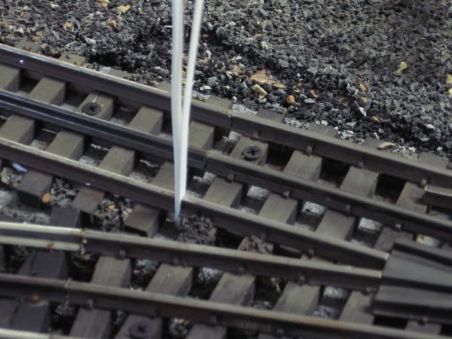
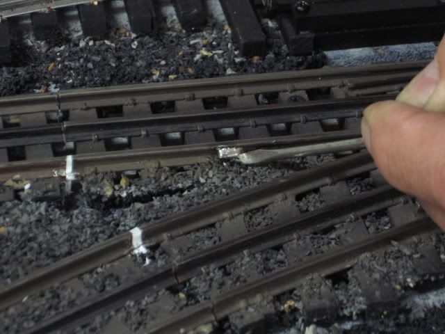
I am installing my first Ross switch (an 072) to replace a lionel 5166.  To add the non- derailing feature, the switch needs a jumper installed  between the two inside rails on the wye.  I hate to make an ugly connection visible on the top and underneath is pretty cramped with the ties. It is not easy to get a soldering angle (at least with the irons and tips I have) to make the connection.  Has anyone come up with some good ideas?  


100_4119

100_4120

Attachments

Images (2)
  • 100_4119
  • 100_4120
Original Post

Replies sorted oldest to newest

I haven't done this yet, and not real sure which rail you are needing soldered in the photo.


I'd 'tin' the wire first.  Use 63/37 solder.  Add liquid flux to the rail.  Apply iron with a clean tip to previously 'tinned' wire and rail.  


Maybe you could use blade connectors?  


Just a couple of ideas.  Let us know how you do it.  I'm sure someone here has done this.

Tin the end of 20 or 22 gauge wires and jam the tinned ends between the split on the bottom at the ends of the inner rails.  It may be necessary to widen the split with a small screwdriver first.  Then heat and add a little solder.  Use a Gargraves insulating pin to isolate the inner rails on the switch.  I did this recently on a Ross switch and some Gargraves switches

Like this?


Update- having a hard time inserting this pdf / picture of where to connect the jumper for non derailing.  I put some arrows on the picture in the attachment.  Seems like a good idea to put it at the end.  Is there any trick to hiding it or just use a dark colored wire?


Attachments

Last edited by hokie71

I was going to include a photo in my initial reply, but didn’t think the wires would even show up.  Well, I just took one and you can see the wires…but you have to look very closely.  I used the green and yellow wires that came with the Gargraves switches.  If you really want to hide them, you can try to find wire the same color as whatever is beneath the track.  Or you could install ballast to cover them…that’s what I will do one of these days.


2015-07-10-3935

Attachments

Images (1)
  • 2015-07-10-3935


colored wire

hokie71, wires can be hidden with weeds, bushes, trash, or yard ballast.


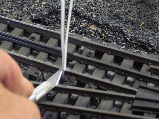
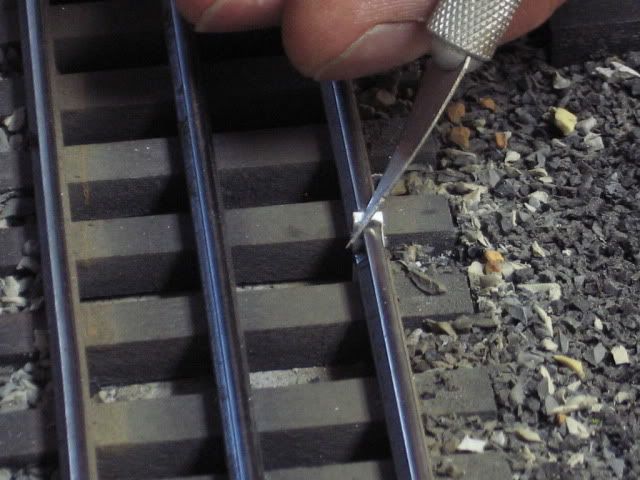
You may want to Back Up and reconsider your wiring.  For Non-Derailing, your individual control wires are soldered to the inside V rails and your outside rails are jumpered together for common.  Your inside V rails should have no continuity with each other or any other track.  Drill holes in track to make soldering easier.


adRoss2close

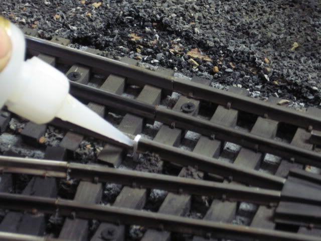
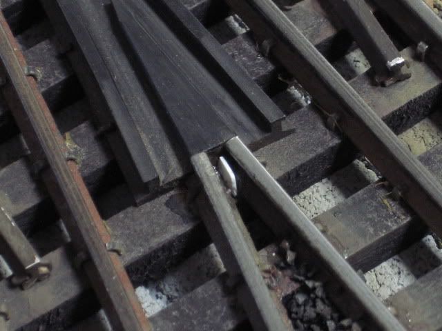
For clarity this photo shows all wiring on top side, the control wires are shown inside black circles.  The bottom of the track Vs have hot glue inserted to keep control tracks electrically separated.  Insulate the control tracks from the running tracks with track pins.


Soldering info that may be helpful is toward the bottom of this page, Toy Train Layout Wiring - Soldering.


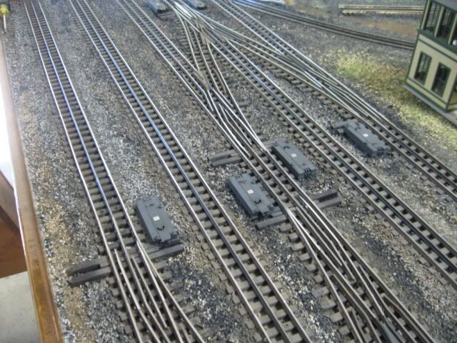
Ross instructions (yours is probably similar to the RossReady):

Regular Switch Manual

RossReady

DZ1000 Switch Machine


Attachments

Images (1)
  • adRoss2close

Susan,


I like the hot glue idea for making sure the inner V rails are isolated.  Sometimes they touch on Gargraves switches.  There was a post about it recently.  https://ogrforum.ogaugerr.com/t...urnouts-just-sharing

When they do touch, I have separated them and jammed a piece of black heat shrink tape between them to make sure they stay isolated, but I’ll try the hot glue next time it happens.  I don’t think Ross has that problem as the few I’ve seen have the center V rails physically separated.


Bob

Susan and all , thanks, I was not thinking when I did my pdf above.  I had a mind set on how I test my Lionel turnouts and was not thinking of what  was really happening.  I like the hot glue idea too.  What I ended up doing for the insulating pins was taking a regular O gauge tubular insulating pin and ground it down on the short side with a dremel tool so it would fit and transition smoothly.  Hit and miss obviously but it worked. If anyone does this, make sure you leave the lip on the pin and grind on the other side, otherwise it slides into the track.


Funny thing on the insulating pins and the transition pins in general: Ross indicates that a 5mm spacer under the switch  is needed to transition to tubular track. I found this is too much, more like  3mm is best.

Add Reply

Post

OGR Publishing, Inc., 1310 Eastside Centre Ct, Suite 6, Mountain Home, AR 72653
800-980-OGRR (6477)
www.ogaugerr.com

×
×
×
×
Link copied to your clipboard.
×
×