I have what I thought would be a simple ask, but so far I've found no simple answer on-line. Specifically, I'm looking for a simple alternate-flashing circuit to power a pair of legacy crossing guard lights, or other similar accessories.

A bit of background: my focus is largely old-school Marx O scale stuff, though I'm hardly a purist and am not adverse to using competing brands or even modern electronics when the benefit (or necessity) outweighs the nostalgia. In this case, the "legacy" activation method for crossing guard lights is to use a pair of insulated clips on the top of one outer rail, feeding an intermittent ground from the opposite side rail through the wheels and axles of passing rolling stock to the two separate light circuits. The net effect of the two circuits is a pretty fair simulation of alternate flashing lights.

However, I'm looking for an alternative means of generating a 'flashing' signal to a pair of lights. To my "old school electrics" brain, the simplest means would be to use a bi-metallic strip with contacts on both sides. At rest, one contact would be connected to one of the lights (note: to work properly, the light would have to be an old-school incandescent bulb, or perhaps an LED with a suitable parallel bypass resistor to draw a sufficient current). On activation, the strip would heat and flex to the second position, breaking the first circuit but activating the second (perhaps closing a pair of separate contacts rather than drawing current through (and thus continuing to heat) the bi-metallic strip). After a short interval, the bi-metallic strip would cool, flexing back to the original position and beginning the cycle again.

What I've described is little more complex than what's in those red-tinted 'flasher' bulbs that used to be included in strings of small incandescent Christmas tree lights to flash the full string, yet I've been unable to locate any source of such flashers that would operate on typical legacy track or accessory voltage. Any suggestions for sourcing, or alternative methods to achieve the same end? ISTM that there'd be a small but viable market for such simple (and hopefully, cheap!) old school devices. Any thoughts?

Original Post

Replies sorted oldest to newest

Never mind -- I think I solved my own problem! It occurred to me that the Christmas light flasher bulbs I mentioned probably have a current capability similar to track-voltage incandescent bulbs, with a relatively low resistance. So, I just hooked one in series with such a bulb, and it worked -- well, for one bulb at least. Putting one in series with each bulb does produce a sort of syncopated alternate flashing:

I've attached an earlier 'breadboard' single light version.

Attachments

Videos (2)
20220616_155505
20220616_153915_001

There are about a dozen companies that make flasher circuits that give a very realistic alternating flash that you can use with Lionel and Marx crossing signals.  They run about 20 dollars but some have adjustable flash speed and cost a little more. You can use a train detection unit to turn the flash on and off as the train passes. I no longer use insulated track sections because of the sensitive electronics in the modern locomotives.

In addition to the off-the-shelf purpose-built flasher modules for model trains, there have been several OGR threads with a more DIY flavor with potential cost savings depending on your comfort level with soldering and/or component-level assembly.

This thread employs an automotive wig-wag flasher module.

This thread and this thread are but 2 OGR examples of a solid-state alternating flasher circuit with circuit boards designed by OGR members.

This thread describes a DIY method that uses eBay/Amazon modules sort-of Lego-style but does not require soldering or messing with tiny electronic components.

One consideration is whether the lamps are switched with a relay vs. solid-state transistors.  The "clicking" of a relay may or may not be objectionable.  And there's a potential issue of long-term reliability of an electro-mechanical relay vs. no-moving-parts transistors.

So there are indeed many "modern" alternatives.

Thanks, Stan, that's a helpful synopsis of the many ways our fellow hobbyists have solved the "flasher" dilemma, some of which I'd stumbled across in my preliminary research. What I was looking for ideally is something that might have been part of an around-the-tree layout "back in the day", using cheap components available last century. Like I said, I'm not adverse to more modern stuff (I've been using static grass and crossing guard sound modules/mini-speakers on my mostly-Marx layout, for instance!), but I was hoping for, and eventually figured out, an old-school kludge. Thanks again!

@Steve Tyler posted:

Never mind -- I think I solved my own problem! It occurred to me that the Christmas light flasher bulbs I mentioned probably have a current capability similar to track-voltage incandescent bulbs, with a relatively low resistance. So, I just hooked one in series with such a bulb, and it worked -- well, for one bulb at least. Putting one in series with each bulb does produce a sort of syncopated alternate flashing:

So your solution was a Christmas light "flasher" bulb in series with each crossing gate lamp?  That is, some times the bulbs will flash together in unison...and slowly drift to where they alternate...and then slowly drift to flashing together...etc.

@Steve Tyler posted:


...

However, I'm looking for an alternative means of generating a 'flashing' signal to a pair of lights. To my "old school electrics" brain, the simplest means would be to use a bi-metallic strip with contacts on both sides....

And to be clear, your research did NOT uncover an 'old school' method to alternate flashing with each bulb on 1/2 the time, wig-wag style (left-right-left-right...)?

Last edited by stan2004

Yep -- each light flashes independently, and since each flasher seems to have its own rate, the lights move into and out of phase, giving a somewhat syncopated effect, as I said. IMHO, this would be somewhat of an improvement over the flashing produced by the rail-top contacts traditionally used (though to be fair, Christmas light-string flashers do take a noticeable bit of time to warm up and start flashing). My hypothetical bi-metallic SPDT would give a true alternate-flash (though probably suffering the same warm-up delay), but so far, I've not found any such actual device, or any other alternative that doesn't involve a good bit of soldering, a number of components, a fair amount of money, or some combination of all three. I know, picky, picky . . . Smirk In any event, thanks again to you and everyone else who responded to, or at least thought about, my query.

In my opinion the origin of John's circuit would lie back in the early days, probably shortly after transistors were invented, because of it's absolute simplicity.  At some point transistors then became more widely available, and finally cheap enough to be affordable to hobbyists who would be interested in building this circuit.

I would suggest that this would place this basic circuit, although not with these specific transistors which came later, right smack in the middle of the postwar heyday in our hobby (late 50's at the latest).

If so this is a contemporaneous solution, and could just as easily have been put into production back then as a bimetallic electromechanical version could have been.

In the end I could attach one of my favorite terms to either or both, 'elegant simplicity', which today means no integrated circuits or microprocessors when not absolutely necessary.  KISS applies here.

Unfortunately neither appears to have been put into production for toy trains back then -- strange but apparently true.

Mike

Fair points, Mike. Back in my ham radio days (early to late '60's, K3SKV), discrete transistors for hobbyist use were still relatively rare and pricey, and vacuum tubes still carried most of the electronic load (anyone else remember VTVMs and tube oscilloscopes?). John's circuit diagram jogged old memories, though since Radio Shack went out of business, I'd have no clue where to go for any of the components anymore. 🤔

For many years I had both a VTVM and several tube equipped 'scopes.  I used the Tek 545 'scope well into the transistor range, it was huge and bulky, but I had a number of plug-ins that made it a very flexible unit.  I bought it dead and brought it back to life.

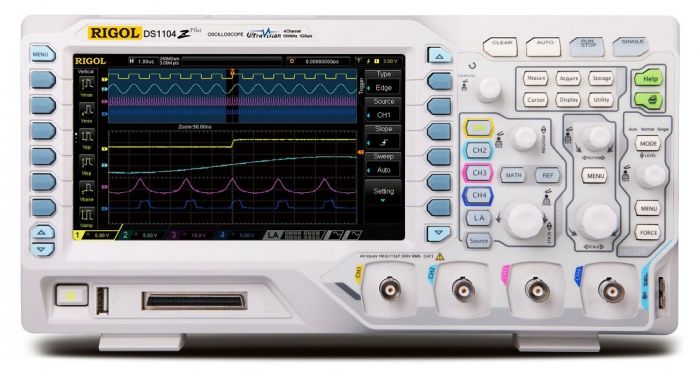
Truthfully, back in those days, a 'scope like my Rigol DS1104Z-Plus with four channels, 16 channel logic analyzer, and arbitrary waveform generators was an impossible dream!  I was working in aerospace in the 1980's, and the 'scopes we had with lesser capability cost more than $10K!  Some things have actually gotten cheaper over the years.

DS1104Z-S PLUS Rigol Digital Oscilloscope

Oh, sure, I know you can source just about anything online (if you're willing to accept the cost and delay of shipping), and I've always supposed some (reasonably) local supplier must have (at least partially) filled the void RS left, but it's just not the same as being able to drop by the local store (in my case, less than a mile from home!) at a moment's notice to pick up the odd resistor or capacitor. Yeah, yeah, "back in my day . . ." -- I'll hobble back to my rocker on the porch now . . . 🙄

Well, the costs for shipping of one resistor is pretty steep in comparison to the price of the part, I'll agree.   OTOH, I buy in bulk, so shipping is not a major part of the price.  I don't see any local places around me that have any assortment of electronic components, so it's either mail-order or nothing.

One way you can minimize the issue of going for "one" capacitor or resistor is to buy an assortment.  There are tons of resistor and capacitor assortments available for a few bucks, that gives you readily available parts in most common values.

I bought resistor assortments in 1/8W and 1/4W thru-hole sizes and also SMT resistors in 0603 and 0805 sizes.  Ditto for ceramic capacitors up to 1uf in thru-hole and SMT.  Finally, I have a large assortment of electrolytic caps.  I probably have less than $50 in all of those assortments, and for common parts, I have them right in hand.

https://www.amazon.com/AUKENIE...Caps%2C56&sr=8-4

https://www.amazon.com/AEDIKO-...&sr=8-8&th=1

https://www.amazon.com/HiLetgo...TG9nQ2xpY2s9dHJ1ZQ==

https://www.amazon.com/Capacit...Caps%2C39&sr=8-3

For many years I had both a VTVM and several tube equipped 'scopes.  I used the Tek 545 'scope well into the transistor range, it was huge and bulky, but I had a number of plug-ins that made it a very flexible unit.  I bought it dead and brought it back to life.

Truthfully, back in those days, a 'scope like my Rigol DS1104Z-Plus with four channels, 16 channel logic analyzer, and arbitrary waveform generators was an impossible dream!  I was working in aerospace in the 1980's, and the 'scopes we had with lesser capability cost more than $10K!  Some things have actually gotten cheaper over the years.

DS1104Z-S PLUS Rigol Digital Oscilloscope

When I got out of college (1970s) and got onto my feet my first big, proud purchase was a Tektronix 547 with a 1A1 plug in. That was almost $3,000 then.

Everyone laughed at me, I had a $3,000 oscilloscope but I drove a broken-down $200 car. They were absolutely correct.

FWIW, the Tek had about 15% of the capability of my current $350 Rigol. It was 50/50 tubes and transistors. No ICs.


Tek 547

Attachments

Images (1)
  • Tek 547
Last edited by PLCProf

Did your research find an old school wig wag automotive flasher using a bimetallic element? I wonder if you could use that as a template to modify (crack open) a 5 cent Xmas flasher bulb and add a 2nd circuit that closes when the bimetallic element is in the cool down phase. I figure the vacuum is only needed for the light which is not needed so a resistor would be needed in place if the filament. Obviously this would be a kludge but would make a good story...

@PLCProf posted:

When I got out of college (1970s) and got onto my feet my first big, proud purchase was a Tektronix 547 with a 1A1 plug in. That was almost $3,000 then.

Everyone laughed at me, I had a $3,000 oscilloscope but I drove a broken-down $200 car. They were absolutely correct.

FWIW, the Tek had about 15% of the capability of my current $350 Rigol. It was 50/50 tubes and transistors. No ICs.

WOW!  $3,000 in 1970 was a LOT of money in 1970!  $3,000 in 1970 is equivalent in purchasing power to about $22,600.21 today, that's the price of four new cars back then!  My 1969 Grand Prix was $5,000, and it was the first car I ever ordered from the factory!  I was fortunate that I got to use company test equipment most of the time.  My Tek 545 was purchased in 1980 for a whole lot less money, and it was pretty easy to get it working again.

I do have a Nicolet logic analyzer that I bought for my business in 1985 for $15,000, that was a hard pill to swallow, but we needed it.  It's still sitting around in my storage, I fired it up a few weeks ago and it still functioned, I was pretty surprised.  I just hate to toss it, even though I have a better option nowadays.

@stan2004 posted:

Did your research find an old school wig wag automotive flasher using a bimetallic element? I wonder if you could use that as a template to modify (crack open) a 5 cent Xmas flasher bulb and add a 2nd circuit that closes when the bimetallic element is in the cool down phase. I figure the vacuum is only needed for the light which is not needed so a resistor would be needed in place if the filament. Obviously this would be a kludge but would make a good story...

You really do think out of the box Stan!   That never occurred to me to even consider.

@Steve Tyler posted:

... though since Radio Shack went out of business, I'd have no clue where to go for any of the components anymore. 🤔

Steve,

For what it's worth Radio Shack did not go out of business.  It simply closed most of its stores.

It's virtually online-only now.

All of the other sources mentioned above are also good places to find parts.

Somebody mentioned vacuum tubes.  I'm tempted to try building a tube-based multivibrator to provide the flashing.  I wouldn't call it an elegantly simple approach to the problem however.  Just the high-voltage power supply alone to get it to work could hardly be called simple nowadays -- too hard to a find an appropriate transformer among other things.

Mike

@PLCProf posted:

When I got out of college (1970s) and got onto my feet my first big, proud purchase was a Tektronix 547 with a 1A1 plug in. That was almost $3,000 then.

Everyone laughed at me, I had a $3,000 oscilloscope but I drove a broken-down $200 car. They were absolutely correct.

FWIW, the Tek had about 15% of the capability of my current $350 Rigol. It was 50/50 tubes and transistors. No ICs.


Tek 547

Ahhhhhh...  I had a great deal of OTJ practice with this beast back in the late 70's.  It was a big step up from my personal Eico 360, which I had bought in 1977 from a guy cleaning out his workshop in transition from his old house to a new one.

For my big purchase instead of a scope I selected a Radio Shack TRS-80 Model III and its corresponding pin-feed printer, partly because I had worked at Radio Shack when the Model I came out and came to like it.  If I recall correctly the Model III and printer cost me about the same as your purchase.

My car wasn't broken down though.  I bought it brand new, on payments, which were $78 a month for 3 years.

Good thing I had a good job.

Haven't we come along way?

Mike

@PLCProf posted:

Oh yeah-

In the late 1980s, the company I worked for bought out the remaining inventory of the similar Model 102s and issued them to be used as dumb terminals for servicing uninterruptible power supplies. I sold mine on eBay maybe 10 years ago. Didn't bring very much.

'Oh Yeah' too.

The model 102 used TRS BASIC, otherwise known as Trash BASIC, just like the TRS-80 Models I and III.  I also had the smaller handheld version of the 102, which came later.

(Speaking of Trash BASIC, Just a couple years ago I had a big project with a well known microprocessor supplier and need to write some code to plug a hole between two of their applications.  I had the time and taught myself Python to do the job in the interest of learning, and applying, something new.  It struck me as odd that unlike C, or Visual BASIC, Python was quite comfortable to me because of my Trash BASIC experience.) 

Mike

@PLCProf posted:

Oh yeah-

In the late 1980s, the company I worked for bought out the remaining inventory of the similar Model 102s and issued them to be used as dumb terminals for servicing uninterruptible power supplies. I sold mine on eBay maybe 10 years ago. Didn't bring very much.

I programmed a simple dumb TTY terminal application on these and we sold about 100 of them to the NYSE for query terminals to replace the old TeleType Model 28 wall mounted terminals on the trading floor.  I spend one day programming and testing my little application, and we leased it to the NYSE for $20/mo for each terminal.  We offered the program to them for purchase, but they wanted to lease it.  I figured over the few years they used these, they paid north of $20,000 for a one-day programming project, best pay I've ever gotten!   The NYSE had their carpentry shop build some nice stands for the RS-100 units and a dot matrix printer for each station.

@Keith k posted:

There are about a dozen companies that make flasher circuits that give a very realistic alternating flash that you can use with Lionel and Marx crossing signals.  They run about 20 dollars but some have adjustable flash speed and cost a little more. You can use a train detection unit to turn the flash on and off as the train passes. I no longer use insulated track sections because of the sensitive electronics in the modern locomotives.

Keith, your last sentence states " I no longer use insulated track sections because of the sensitive electronics in the modern locomotives."  I was wondering what the issue is with insulated sections?

I'm stating a 10'x12' layout, and I was planning on using a number of insulated track sections to control crossing gates and flashers. I'm also building a fleet of newer engines, Legacy, LC+2.0.

Thanks  - Tony

When I had several insulated track sections I noticed that during night time running when the initial circuit was completed there would be a small spark at the point where the first wheel bridged that gap. The track was always clean as were the wheels of the locomotives and cars.  I asked my repair person about the likely hood of this causing a board failure and he said that although it is unlikely it is possible. He has had several customers that had recurring problems that ceased after removing the insulated track sections that they believed were the culprit.   A major plus is that I found  I really like using the train detectors and I can move them around without having to cut track or add insulators.  Plus what John said in his previous post about traction tires.

Last edited by Keith k
@Keith k posted:

When I had several insulated track sections I noticed that during night time running when the initial circuit was completed there would be a small spark at the point where the first wheel bridged that gap.

Keith, the reason for the spark is you have a sensing circuit that is drawing too much power.  That's one reason I came up with the Insulated Track Signal Driver, Rev. 2, it draws very little power through the track connection and won't generate sparks at the wheels.

Attachments

Images (1)
  • mceclip0
@stan2004 posted:

Did your research find an old school wig wag automotive flasher using a bimetallic element? I wonder if you could use that as a template to modify (crack open) a 5 cent Xmas flasher bulb and add a 2nd circuit that closes when the bimetallic element is in the cool down phase. I figure the vacuum is only needed for the light which is not needed so a resistor would be needed in place if the filament. Obviously this would be a kludge but would make a good story...

Hmmm . . . I was about to respond that the filament certainly wouldn't last very long if exposed to oxygen, but you may be right, that the bimetallic strip should continue to heat up and flex as long as current is flowing (BTW, I doubt a resistor would be necessary, since the "controlled" bulb is in series and thus limiting current flow, and this of course assumes the by-then-burnt-out filament can somehow be bridged to close the circuit). However, the filament may be an indispensable part of providing the necessary heat, and current alone may not sufficiently heat it. Only a bit of experimentation on some *very* small and fiddly  components would yield the answer. If I get bored this weekend, I may see if the "exposed" bi-metallic element alone will control a light, just for giggles. If *that* works, I'll see if I can figure out how to get the "open" element to close a secondary circuit to activate a second light. Sheesh, the things I get myself into . . .

Anyone remember this little gem?

Looks like an early-gen TRS-80, which IIRC sold for between $600 and $1,000, back in the '70's!

BTW, I was recently cleaning out my workshop, and came across an 8-meg (!) TRS-80 hard drive console (about the size of an entire early PC!) which for some reason I'd salvaged decades ago when my law firm upgraded to IBM computers. I dropped it on eBay, and it sold in a couple of days for a "Buy It Now" price of $199, plus a huge shipping bill! Shoulda asked for more . . .


Somebody mentioned vacuum tubes.  I'm tempted to try building a tube-based multivibrator to provide the flashing.  I wouldn't call it an elegantly simple approach to the problem however.  Just the high-voltage power supply alone to get it to work could hardly be called simple nowadays -- too hard to a find an appropriate transformer among other things.

Mike

Ohh, ooh, ooh -- maybe you could mount it in plain sight on the layout and 'disguise' it as a power substation or nuclear generating plant! Three Mile Island, maybe?

Add Reply

Post

OGR Publishing, Inc., 1310 Eastside Centre Ct, Suite 6, Mountain Home, AR 72653
800-980-OGRR (6477)
www.ogaugerr.com

×
×
×
×
Link copied to your clipboard.
×
×