I apologize if this is a rerun, but has anybody used this solder glue successfully?
Attaching links are not supported anymore?


|
|
I apologize if this is a rerun, but has anybody used this solder glue successfully?
Attaching links are not supported anymore?
Replies sorted oldest to newest
I know there is conductive paint,
There is no reason it shouldn't work with a conductivity of 13 ohms per cubic centimeter. That is a significant increase in resistance to your circuit over solder, but should still work. I think I would try to insure a good mechanical connection prior to gluing. Twisting the wires, etc. Hopefully the glue is not porous enough to allow atmospheric elements to oxide the contact surfaces.
I would personally prefer to solder. It provides a superior electrical and mechanical connection.
IMO, this is a total gimmick! Dry to the touch in two hours? You have to wait a day to use your new "solder" job? We won't even get into how expensive it is compared to solder.
Forget this junk and just learn to solder, it's easy and suitable tools are cheap! I truthfully don't know why this topic keeps coming up.
If you don't want to solder, wire nuts work just as well. I've been using them for 40 plus years without any problem. Wiring in residential and commercial buildings use wire nuts.
lionelbob posted:Attaching links are not supported anymore?
I'm not sure of this question. You had the link in your post. I changed the words so it was a more readable link. Nothing has changed here. You can easily post links, just as we always have.
DennisB posted:If you don't want to solder, wire nuts work just as well. I've been using them for 40 plus years without any problem. Wiring in residential and commercial buildings use wire nuts.
While that's certainly true, using 15-20 wire nuts inside your locomotive will be a kludge at best, and certainly a lot more difficult to fit in than neatly soldered wires with heatshrink on them. ![]() They have their place, but in tight quarters, they're not the ideal solution.
They have their place, but in tight quarters, they're not the ideal solution.
I totally agree. I was specifically talking about layout wiring.
No problem with them there Dennis, plenty of room under most layouts. ![]()
gunrunnerjohn posted:IMO, this is a total gimmick! Dry to the touch in two hours? You have to wait a day to use your new "solder" job? We won't even get into how expensive it is compared to solder.
Forget this junk and just learn to solder, it's easy and suitable tools are cheap! I truthfully don't know why this topic keeps coming up.
John, I've been soldering since 12th grade (1970) in Frankford High school electric shop. I can hold my own with that. I was just wondering if anybody else had used this product.
Naw, but I totally agree w/John
Bob, if you solder, to what end would you need this product? I'm sure it would create inferior connections, and just by reading the usage, it's certainly a much larger PITA to use than soldering, at least IMO.
Since you do know how to solder, I'm just trying to understand what your impetus would be to even consider it, and I'm not trying to start an argument. ![]()
I can think of some [infrequent] modelling situations where a conductive glue would be useful, if soldering heat would damage adjacent materials and there isn't room to make a good mechanical connection.
Ace posted:I can think of some [infrequent] modelling situations where a conductive glue would be useful, if soldering heat would damage adjacent materials and there isn't room to make a good mechanical connection.
Agree. I certainly wouldn't see it as a replacement for soldering, but it could come in handy for a repair in a spot where heat would be a problem. Strictly a niche product, but potentially useful.
That's only it it actually works, of course. ![]()
I use wire nuts for most connections, but I can see one use for the solder glue. I used the Gargraves pins that have wire drops soldered to them. They work very well, but I was careless and my foot caught the wire from one of the drops and tore it loose from the track pin. Of course, the track pin joins two sections that are beneath an overhead platform and inaccessible from above. However, from below I can put a drop of the glue on the wire, push it back up until it contacts the bottom of the track pin and use tape to hold the wire in that position. Overnight, it should be fixed (if it works).
So, like many specialty tools, it might be the right tool for certain jobs. For the price it is certainly worth a try.
With the resistivity of the material, I seriously doubt you'd want it carrying amps of current!
Conductivity: 13.16 Ohms per cubic centimeter.
Let's assume you have a fairly secure connection and you only have a couple of ohms of resistance. If that track connection is called on to carry 5 amps, the joint will dissipate 10 watts. It won't take long for it to get really hot in there!
I suspect this is for low current and low voltage applications.
I agree w/Dennis completely. Nothing like a wire nut especially after using them for over 50 years. I agree that could be a possible use but I have never found one.
Ken M
I love advertising like that!
1. Conductivity is measured in Siemen-meters or equivalent, resistivity is measured in Ohm-meters or similar. Ohms per cubic centimeter is a made-up unit, but I can "mis-understand" why someone might assume it is valid.
2. Assuming that they really mean that the resistivity is 13.16 Ohm-centimeters, the resistivity of plain 63/37 solder is 14.5 micro-ohm-centimeters, making "Solder Glue" a million times less conductive than solder.
If it wasn't sold out I would buy a jar just to test it!
Similar stuff has been around for years, and long ago I did actually try some. It was very unimpressive, and I have no reason to believe this will be vastly superior.
I was also trying to wrap my brain around the conductivity number, the only thing I can come up with is a block of the stuff one centimeter square had about 13 ohms of resistance. That was just a guess as I have also never heard that term before. ![]()
I suggest you take Gunrunner John's sage advice.
The conductivity spec intrigued me which is why I mentioned it in my first post. The need for such a large cross section to get that resistance made me cringe.
Hence my warning about high currents. I suspect you'd have some interesting connection fires. ![]()
I only use Kester 60-40 solder, 1/32 and 1/16 inch diameter, for feeder wire soldering to tracks and circuit board repairs. Considering terminating wire connections below train boards by type of connection;soldering(permanent) or layout disassembly or component replacement(wire nuts). All joints must be tight for continuity and no arc flash over heating at bad solder joints, check feeder wire solder joint by pull test on wire.
I use the .020 diameter 63/37 Rosin Core for circuit board repairs, the .031 solder is the size I use for general wiring.
OK, I'll respect Gunrunner's advice and do the repair another way. Last thing I need is a hot spot or fire in a fairly inaccessible area. I've got a large fire extinguisher in the train room, but I'd prefer to be cautious so I never have to use it. The repair would have been on the center rail wire (I have drops every 3rd section of track). I'll go at it by drilling a hole from under the table and putting the wire into a blade connector which I put into the underside of the rail. (Gargraves track).
If you follow MTH DCS advice you only need track feeders every 10 feet or so. My double loop single block 9x7 feet layout has the feeders every 20 feet or so. I get 100% DCS signal strength on the entire layout.
DCS, according to MTH, needs star track wiring. From each lock-on a pair of 16 or 18 gauge wires run back to a terminal board at the DCS TIU and the power brick. I run them as a twisted pair which tends to make them more impervious to external electrical noise. The wire runs are continuous (no splices or tees) from terminal to terminal using crimp on end fittings (no solder). This is called "STAR" wiring by MTH. The type of wiring with a circulating single feed pair onto which each lock-on tees is called Buss wiring, I believe, and should not be used for MTH DCS as it can impact the resultant DCS track signal strength.
Wire nuts are for house wiring. To me it makes no sense to use wire nuts when, if you must make a connection, there are crimp connectors that work perfectly well and are impervious to falling apart, in my experience. Crimp connections without solder have been used extensively on Military equipment and even in space projects (at least the ones I worked on for over 30 years in aerospace). I was appalled the first time I took the body off a MTH DCS Proto 3 engine and found internal connections made with wire nuts. This is not good for an expensive MTH Premier engine!!!
As for soldering, it only takes practice remembering one important thing: Heat the joint and use the joint to melt the solder, not the iron. The results should be a shinny smooth solder joint. If the surface is crystaline looking, it is a "cold" resistive weak solder joint.
LDBennett
Thanks for the information.
Actually, along the straight runs I used the 3 foot sections of Gargraves, so in lots of areas 3 sections of track is 10 feet. I have TMCC on one loop but prefer the simplicity of Lion Chief +. Most of my engines are conventional.
As a kid I used to scratch build frames for slot cars by soldering the thin steel rods together. Soldering does make the best joint but I don't particularly enjoy doing it. (And on the stainless outer Gargraves rails, it is quite difficult.)
I used 14 gauge wire to power my 3 main lines, so the wire nuts work fine there. The short drops from the Gargraves track pins look like 16 or 18 gauge. I expect to add in line fast blow fuses and TVS to each main line and the freight yard. I do use crimping to put connectors on wires going to my terminal blocks for lights, for the wire attachments to the transformers, etc.
I appreciate all of the suggestions and guidance!
LDBennett posted:As for soldering, it only takes practice remembering one important thing: Heat the joint and use the joint to melt the solder, not the iron. The results should be a shinny smooth solder joint. If the surface is crystaline looking, it is a "cold" resistive weak solder joint.
Well, almost. ![]() While it's certainly true that the joint must be hot enough to melt the solder, the easiest way to accomplish that is to have a little solder in the iron to transfer heat to the joint. After you get the joint heated up, you feed in the solder to actually make the connection. Putting a dry iron on the joint will take a lot longer to heat up the connection.
While it's certainly true that the joint must be hot enough to melt the solder, the easiest way to accomplish that is to have a little solder in the iron to transfer heat to the joint. After you get the joint heated up, you feed in the solder to actually make the connection. Putting a dry iron on the joint will take a lot longer to heat up the connection.
I assumed (perhaps wrongly) that the tip of the soldering iron would be tinned. Putting a glob of solder on the soldering iron to transfer the heat I suppose is ok but I don't do that as it usually adds too much solder to the finished joint. I let the iron heat up the joint by itself. It takes a bit longer but whose in a hurry? There is more than one way to skin a cat, I guess.
After my first exposure as a teenager to soldering on my Eico Amplifier in about 1955, I have since done better at soldering. The Eico failed to work after assembly. I took it to the local HAM/Audio store and they cleaned up the solder joints and all was well. I have had a bit of practice since then.
Soldering that amazes me is production wave soldering. The circuit board is held close to a the top of a pool of molten solder. A paddle in the automated machine stokes the pool to make a wave of solder that moves down the pool and laps up on the bottom of the circuit board to solder all the component stuck in the copper plated through holes. The whole board is soldered in one pass. All the assembler has to do is cut off the pigtails of the components sticking through the solder joints. NEAT!
LDBennett
gunrunnerjohn posted:Forget this junk and just learn to solder, it's easy and suitable tools are cheap!
Not that I even considered the glue, but thank you for that advice. I have the tools and materials, I just needed that kick-in-the-pants encouragement to start learning how to solder effectively.
LDBennett posted:Soldering that amazes me is production wave soldering. The circuit board is held close to a the top of a pool of molten solder. A paddle in the automated machine stokes the pool to make a wave of solder that moves down the pool and laps up on the bottom of the circuit board to solder all the component stuck in the copper plated through holes. The whole board is soldered in one pass. All the assembler has to do is cut off the pigtails of the components sticking through the solder joints. NEAT!LDBennett
We had a wave soldering machine at the aerospace company I consulted at in the 80's and 90's, it was an interesting process. Obviously, wave soldering is only applicable to thru-hole components. Now that most everything is moving to surface mount, different processes are called for. Nowadays, they create a solder stencil, put the solder paste on in one swipe with the stencil, and then place the components using automated pick-n-place machines. A trip through the IR oven and they're all soldered. ![]() If you ever get the chance, visit a PCB assembly house and watch the process, pretty interesting.
If you ever get the chance, visit a PCB assembly house and watch the process, pretty interesting. ![]()
LDBennett posted:Wire nuts are for house wiring. To me it makes no sense to use wire nuts when, if you must make a connection, there are crimp connectors that work perfectly well and are impervious to falling apart, in my experience. Crimp connections without solder have been used extensively on Military equipment and even in space projects (at least the ones I worked on for over 30 years in aerospace). I was appalled the first time I took the body off a MTH DCS Proto 3 engine and found internal connections made with wire nuts. This is not good for an expensive MTH Premier engine!!!
I'm unsure, in applications without a concern for lots of low frequency vibration, if one mechanical connection is any better than another. Using wire nuts inside of an engine seems a curious choice because, in theory, they could loosen over time from vibration, however I have never had one work it's way loose in an engine yet. For layout wiring, I don't see wire nuts ever working their way off. I would actually think that a wire nut would be preferred as it would provide, in the smallest amount, less resistance than a crimped on connector, and most certainly a better connection than the average crimp folks can accomplish with standard crimping pliers. I've no doubt that the crimps from industrial presses are fantastic, as they tend to actually squish the wire into the form of the crimp, but with hand tools at home the connections are never so solid.
Straying quite far off topic, I'm curious about the effects of the popular 'suitcase' style connectors on the wire they are connected to. As these connectors 'bite' into the wire I would imagine they cur away a small portion of the thickness of the metal at that point. Does this have any effect on the current that the wire can then carry, as it's gauge has been, if only slightly, reduced?
2AM brain wanderings are a strange thing.
JGL
JohnGaltLine posted:2AM brain wanderings are a strange thing.
They sure are, get some sleep! ![]()
![]()
Y'all make it sound like soldering is easy. I have been practicing for a while and very seldom get a "pretty joint" but it works. I am a slow learner. A friend say my Weller 140/100W is too big and I should get a "iron"
Brent
I use my old Weller 100/140 for track and heavy duty soldering. Stuff like brass stacks for smoke units, #12 wire, etc. For finer work, I use a temperature controlled soldering station.

I too use a temperature controlled soldering station. I got mime from Radio Shack before they closed the store near me. It works great. About 30 years ago I found the one that our assembly girls (PC board assembly) from work used and it works great. I gave it to my son for his RC cars back then. My Radio Shack model works almost as good. It is only about five years old and has a digital read out.
LDBennett
Thanks Y'all, I am now in the hunt for a temperature controlled soldering station, will check Radio Shack Saturday, yes, there is one in Rockwall TX.
Brent
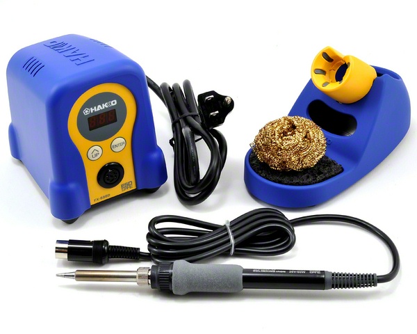
A piece of advice. Forget Radio Shack for this and look at quality manufacturers of soldering stations. I strongly recommend the Hakko FX888D, it's a quality tool that will give you years of reliable service.
Do yourself a favor and follow GRJ's advice. That Hakko station he linked is an excellent choice, very good quality, lots of different tips available and it works great. It's very reasonably priced as well, IMO. I ditched my old Weller station for one of them and never looked back, the Hakko is far superior.
There are also some package deals available for the Hakko above that include an assortment of different tips and maybe another thing or two. I got one with several tips, the total price of the package was less than adding the tips separately at a later time. Just another option. Here is the one I got: Hakko FX888D-23BY Digital Soldering Station with Chisel Tip Pack T18-D08/D12/D24/D32/S3
Access to this requires an OGR Forum Supporting Membership
