
Key Model Imports AC-12 Cab Forward #4294

A unique way to present such an amazing replica?

How do you represent the Mona Lisa of model railroad models? I can shoot studio shots all day and never command the emotion and the feel of this incredible model; only seeing in person can you truly realize how profound this project is. I decided to concentrate on making one look as real as possible in a natural environment. I've been told by the aficionados and the lucky few owners of these incredible replicas that she's too clean in these images. They are correct; however let's keep it a little faux, after all it is a 1:48 scale replica! 

IMG_9526

IMG_9523

IMG_9522IMG_9520IMG_9521IMG_9524

These images are licensed to Key Model Imports, if you repost them please be polite and provide credit to either me or Key Model when doing so. 


I hope you guys enjoy them as much as I did making them. 

Attachments

Images (6)
  • IMG_9526
  • IMG_9522
  • IMG_9520
  • IMG_9521
  • IMG_9524
  • IMG_9523
Last edited by Erik C Lindgren
Original Post

Replies sorted oldest to newest

SANTIAGOP23 posted:

Amazing captures! I also enjoy the bare brass close-ups on Key's website. I bet they run like heaven.

Would love to see a Youtube review by  Gary Schrader.

HO crowd be drooling!

Gary is the one that did all the building on the corrected models for the builder. They were 7500.00 each and are all sold out. On ward for other importers. Any one know what the status on the big boy is?

Bob

SANTIAGOP23 posted:

Would love to see a Youtube review by  Gary Schrader.

HO crowd be drooling!

Gary did a YouTube review of the pilot model a few years ago at https://www.youtube.com/watch?v=V3Uk1xiheao

Video here describing the scale wheel profile... https://www.youtube.com/watch?v=eVptvhy_AS0

And working flexible pipe joints here... https://www.youtube.com/watch?v=LoosaBMGLQM

...gregg

Bob Harris posted:
SANTIAGOP23 posted:

Amazing captures! I also enjoy the bare brass close-ups on Key's website. I bet they run like heaven.

Would love to see a Youtube review by  Gary Schrader.

HO crowd be drooling!

Gary is the one that did all the building on the corrected models for the builder. They were 7500.00 each and are all sold out. On ward for other importers. Any one know what the status on the big boy is?

Bob

These tend to be long term projects for serious investors. JMO

Just noticed Gary's review on Key's website. It seems to be an alternative mobile only site, but he goes through all the road number details and time frames. It really gives you a sense of the complexity in his research and Key's ability to deliver. What a  project! Mind blowing  really. Wow! This really makes me want to order a GS6 in WP... maybe they are next after the big boy?

Erik C Lindgren posted:
AGHRMatt posted:

Beautiful model. Great photo work, Erik. Is that bridge shot the module project you guys were working on?

Yeah Matt!

CB88FD93-1D39-4CDA-9D17-23053086E98E

In this view I still needed to add smoke pellets...  

...

Nice.

I decided to dust off some bridge drawings I have to build a photo platform module. The bridge was built by Pacific Electric in 1913 and I can remember when trains ran under then backed across it to serve a steel plant on the north side (left) of the bridge. The City of Torrance had issued a Request for Proposals (RFP) to rehabilitate/retrofit the bridge. It actually appears on the city seal and was deteriorating. The RFP included  a very good set of drawings which I downloaded. I contacted the City yesterday to find out how the work turned out and they sent me this photo.

Bridge Lights on western face of bridge

Attachments

Images (1)
  • Bridge Lights on western face of bridge

Erik - the technical side of that is the eccentric crank is probably loose, and will cause great grief during an operating session.

Eccentric cranks aim more or less at the axle center bore.  They are about 15 degrees off to impart motion to the eccentric rod.  A loose eccentric will ultimately wind up in an over-center position, bending the rod or worse.

Shaft Loctite is your friend.

I agree - your photographs are works of art.  If production runs can be considered art, then this model qualifies.

mark s posted:

The eccentric crank is not loose...that's how it was positioned on those locomotives.

I don't think so, Mark. The position of the eccentric crank should not have any bearing on either forward or reverse movement of the engine. The position of the block within the link, determines valve position and length of valve stroke, no matter the direction of movement. 

 Recall, it is a locomotive running backwards (perhaps someone with a greater mastery of valve gear can explain why the eccentric crank is lagging, not leading).


Well, Mark is partially correct - some locomotive operators wanted the radius rod to be down in normal operation, so Baldwin rigged the cab forward engines for reverse running.

But look again at that photo - the crank is a quarter turn away from any reasonable setting, forward or reverse.

Somebody help me on this - this crank is way, way out of normal position.  Plenty of prototype photos exist to back me up.

Last edited by bob2

Well, I keep forgetting to hit the "post" button after I hit the "add photo" button.

Here's a photo.  Note that, in addition to being set up to run backwards (crank set toward front of locomotive, not front of engine), the crank bolt that holds the rod is completely contained by the driver center.  That is, it is roughly 15 degrees from a centerline from crankpin to axle center.  image

Attachments

Images (1)
  • image

Check the prototype cab forward photos on Key's website; the eccentric cranks are angled away from the cylinders, as opposed to the much more common posture of pointing toward the cylinders.  http://www.keymodels.net/id16.html                          Today's Soo Line #1003 2-8-2 has the eccentric crank pointing away from the cylinders, too.   This was a bit more common on the locomotives built in the approximate 1913 era, such as #1003. See photos of articulateds built in the 1913 +/- period......lagging eccentric cranks, not leading.

Eric's photo just above does portray the eccentric crank being in a rather extreme position; perhaps it is loose. But then, all of Eric's other photos look just the way cab forwards looked in operation, in photos of the period.

Have never heard a satisfactory explanation on why the eccentric cranks on some locomotives lag,  and on far more locomotives, they lead.

Last edited by mark s
Number 90 posted:

Nobody does smoke better than you do, Erik.  My hat is off!

I agree, it's some of the better photoshopped real-life smoke effects on a model I've seen. I have noticed plenty of people in magazines (especially RMC) are doing it, but most do it very poorly. The lighting doesn't match the smoke at all and there are usually very well-defined borders between the smoke photo and the real model. These shots don't have that look (thank goodness).

This one, looked a little odd to me until I realized that I wasn't seeing the drafting from the end of the stack you'd expect from a locomotive at speed (not to mention the angle of the smoke for something that's supposed to be moving at all):

Thought not perfect, it's still better than most post-shot smoke digital effects I've ever seen.

I look at this shot and think back to when I heard that Phillip Anschutz was looking over the real loco at Sacramento in the museum one night, which led some to think he'd pondered maybe taking a page from UP's playbook and pulling that AC-12 out of there and getting her restored to operation. I'd rather have seen that happen than the 4014 restoration currently underway!

Me too!

Have never heard a satisfactory explanation on why the eccentric cranks on some locomotives lag, and on far more locomotives, they lead.

My explanation above was not satisfactory?

The other possible reason is Walschaerts gear on slide valve cylinders.  The intake ports are different, and a different motion is required.

Erik - Gary will spot it quicker than I did.  It will take him 30 seconds to fix it.  The guy is a genius with this stuff.

With respect to the question of why the eccentric cranks on some locomotives lead the main crank, while on others they lag, here's a partial explanation for Walschaerts gear, at least. 

Engines fitted with Walschaerts gear can be arranged to derive the proper motion of the valve stem for forward travel of the locomotive by either (1) dropping the link block in the rocking link or (2) raising  the link block in the rocking link. The eccentric crank will therefore lean ahead of the crank pin, or will lag behind it, when rods are at BDC, depending upon whether the proper valve motion for forward movement (or reverse) is being derived from the top or the bottom of the rocking link. 

In the most common application of Walschaerts gear, the bottom of the rocking link is closer to the cylinder/valve chest than the top of the link when the rods are at BDC. In other words, the rocking link slants backward, like this -- \ .  When the gear is set up this way, the eccentric rod leads the crank pin.

In the less-common arrangement, however (which is geometrically opposite), with the rods at BDC, the rocking link leans forward, like this -- /.  In this configuration, because the valve motion for forward travel of the locomotive is derived from the opposite end of the rocking link, the eccentric pin lags the crank pin in order to impart opposite motion to the rocking block.

This difference can be seen in the photos below of two locomotives fitted with different configurations of the same basic Walschaerts gear. Presumably the common arrangement had some design and/or production benefits, but I don't know exactly why it became the standard. As far as I know, Baker gear was always driven by a leading eccentric crank, because the basic mechanism was not reversible in the same way as the Walschaerts rocking link.

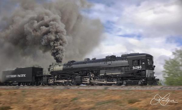
(1) The most-common arrangement for Walschaerts gear: eccentric crank leading the main crank, with the rocking link leaning backward, when rods are at BDC:


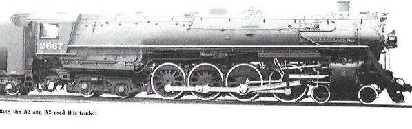
(2) The other possible arrangement for Walschaerts gear: eccentric crank lagging the main crank, with the rocking link leaning forward, when rods are at BDC:


Attachments

Images (2)
  • mceclip0
  • mceclip1

BOB2 -- I'd like to know more about that. What do you think might have been the reason for wanting the rod to be down in normal (i.e. forward?) operation? Perhaps it was related to the "preferred" operation of the reversing lever in the cab --whether to "push" or to "pull" for the same result. I can't think of any reason why one configuration would be mechanically preferable to the other, since the upper and lower halves of the rocking link are symmetrical and the valve events would therefore the same whether they are derived from the top or the bottom of the link (so long as the motion of the link is reversed with respect to the preference for "radius rod down" versus "radius rod up" as the normal position). 

Just to illustrate BOB2's comment about the cab-forwards having been set up for reverse running in regular service, I've posted the photo below (again from MR Cyclopedia Vol. 1). The eccentric lags the crank (when rods are at BDC) with respect to its relation to the the cylinders, and the rocking link has been positioned opposite the common Walschaerts arrangement so that the engine will run in "reverse" (i.e. "forward" with respect to the engineer's position because the whole locomotive is turned around) when the engineer operates the reversing lever in the "normal" manner.

In other words, the engineer doesn't have to compensate in his mind for the fact that the engine is running backward when he manipulates the controls. At least, that's how I understand the purpose of the valve gear arrangement shown here: Forward motion of the engine is achieved by "dropping" the block and radius rod in the rocking link, just as the engineer would do on a regular SP cab-behind engine. This has been an interesting discussion about something I hadn't paid much attention to before. 

I often refer to The Steam Locomotive in America: Its Development in the Twentieth Century by Alfred W. Bruce, for helpful explanations, but Bruce does discuss this question explicitly.


Attachments

Images (1)
  • mceclip0

Are the eccentric cranks on the Key model held in place only by the pressure of the nut?

On the two Sunset/3rd Rail engines I own, the position of the eccentric cranks is determined by a narrow tab cast into the back face of each crank (like a "key") that fits into a slot in the main crankpin. This seems like a pretty secure arrangement, as long as the slot in the main crankpin is in the right place when it leaves the factory. 

Add Reply

Post

OGR Publishing, Inc., 1310 Eastside Centre Ct, Suite 6, Mountain Home, AR 72653
800-980-OGRR (6477)
www.ogaugerr.com

×
×
×
×
Link copied to your clipboard.
×
×