
Replies sorted oldest to newest

Originally Posted by Mike Miller:

Hello everyone,

I have a few questions as I start to lay track for my new layout. 

1) What do I do when cutting Atlas track and that cut falls in the middle of a tie ?


I simply removed that tie, and latter added loose ties to fill any remaining gaps. 


2. Do you solder the feeder wires directly to the track rails or to the track joiners ?


always soldered directly to the rail. Sometimes drilling a small hole into the rail provides a better electrical connection for the wire, and is easier to solder, especially the center rail.    


Thanks,

Mike


Hi, Mike -

 I found what HotWater said (below, in part) to be very true:

 "Sometimes drilling a small hole into the rail provides a better electrical connection for the wire, and is easier to solder, especially the center rail."

 And in so doing was that I found that a Ø5/64" hole works fine with 16AWG and a #0x1/4" Pan/Phillips Head sheet metal screw to hold the wire without need for soldering.

 When I started doing these connections, I used a small washer under the screw, but found that it was not necessary - see picture below w/o and w/washers. 

 New Rail Connections A-B

 The Steps: (Edited 14 Feb 2017 to add step descriptions)

 Drill the holes on the track and the layout surface

NEW Rail Connection 01 all four holes DSC03562

Insert the non-stripped wire through the layout surface hole and strip it. Easier to keep the strands together by stripping it at this point.

NEW Rail Connection 02 wires thru DSC03566

Insert the wire into the hole carefully to keep it from fraying.

NEW Rail Connection 03 one wire in place DSC03569

At this point, I use a sharp punch and insert it in the hole with the wire to create a starting hole for the screw.

NEW Rail Connection 04 wire ready for screw DSC03570

Add the screw and all done!

New Rail Connection 05 B DSC03593

 Good luck!

 Alex

Attachments

Images (6)
  • New Rail Connections A-B
  • NEW Rail Connection 01 all four holes DSC03562
  • NEW Rail Connection 02 wires thru DSC03566
  • NEW Rail Connection 03 one wire in place DSC03569
  • NEW Rail Connection 04 wire ready for screw DSC03570
  • New Rail Connection 05 B DSC03593
Last edited by Ingeniero No1

I highly recommend the method posted by Ingeniero No1 above for powering your Atlas track. I followed Alex's methods (from his build thread, and I also asked him a question or two) with my layout that's still being constructed and it's a great way to add power to your rails. I used the 5/64" drill bit just as Alex posted and got the #0 x 1/4" Black Oxide Pan Head Phillips screws from his source, Micro-Fasteners.


Works great, makes a great connection, no soldering so no chance of melting plastic ties and is very easy to do once you get going. Also easy to change around if you decide to redo track or anything like that. I can't say enough good things about this method!


So far I have not had to cut any of my track, so can't comment there. I would follow Hot Water's advice on that one. That's what I will do if I ever have to cut any track. I will probably also use the rail pieces Mike CT posted.

Last edited by rtr12

I started by using the rail joiners that had the wires already soldered to them, but ended up saving the expense and just soldering to the rails.  I had to cut a lot track and had to remove a lot of ties in the process.  The as Jack said I just go back and slip ties in under the track where needed.  You can also paint the wires and rails after they are installed to make them nearly invisible.


Art

Originally Posted by Mike Miller:

Hello everyone,

I have a few questions as I start to lay track for my new layout. 

1) What do I do when cutting Atlas track and that cut falls in the middle of a tie ?  

2. Do you solder the feeder wires directly to the track rails or to the track joiners ?    


Thanks,

Mike

1) What I did was to trim the other end enough to move the cut point just off the tie.

2) I did some of both.  However, I soldered all the track joiners so it was often easiest to do the wire to them, too.

Originally Posted by brwebster:

When possible I slipped the feed wire in between the joiner and rail then soldered.  I had never thought of the method that Alex uses and I really like it...especially if connections are done on the back side of rails, out of sight.


Bruce

That's what I did with Alex's connection method, back side of track. I have no ballast yet and they are pretty well out of sight now. I don't notice them unless I am trying to find one, and I have to look for them. With ballast I would imagine they would be hard to spot. 

I have used Atlas silver nickle track about 17 years. The first rail joiners were flimsy and I replaced them with the newer ones ( at the time; don't know if there is a newer version ). They have been problem free and I put them every 3 feet or so. I also put them one all three legs of a switch. I have had zero problems. It seems quite time consuming to solder or screw that many joiners to the layout. It would certainly be secure though, and if you have the time why not?

The ties underneath can simply be clipped off anywhere with a little snip. As someone noted Atlas makes end ties; they are necessary when you use their flex track. I have used plenty of that and like it. There is a learning curve to cutting it square and matching up with the other side.

In case you are wondering I have forgotten how many cases of track I have used. I recall my 1st layout had 36 switches ( turnouts ). The room is 24 x 24 and there are 5 levels of track. The upper most around the room line has about 2 "scale" mile of track.

Before I started the "first" serious layout I bought every kind of track there was and looked them over real well; I chose Atlas, others don't. Viva la difference.

Each layout has been the "final" layout.

Ernie

ibew701 posted:

Kris

I use a 40W soldering iron on Atlas track.  I rough up the surface to be soldered and then put a little solder on the side of the rail.  I use stranded wire that is pre-tinned and then just enough heat to melt the wire to the rail.  Takes 5 seconds, if the iron is hot.

Jim

Above is sound advice and very DCS friendly. The 5 seconds also will not melt nearby ties. Pretinned and a little flux paste on the freshly scraped rail..5 seconds or less. No srews,no drilling!

Last edited by willygee

Dear All

Thanks for the replies. Sorry about the delay on my part just have been very busy. Between selling the Fastrack, purchasing the Atlas track, life, work and family, so little time to enjoy the trains if any. I almost forgot that tax man wants some of my time as well to fill out some form again.

Dear Jim

Thanks for the info. With the  information you supplied me,  instead of purchasing the Atlas terminal connectors I went out and purchase a Hakko FX888D Digital Soldering Station. I am going to use this to make the roll your own terminal for Atlas. Beside is is a good soldering station and I can use it for other parts of the layout.
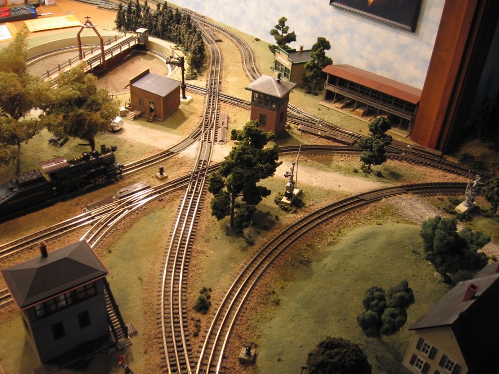
Dear Mike CT

Very nice work, I am impressed. If you area located in Fairfield county CT I would love to buy you a cup of coffee and talk about your layout.

Dear Ernie

Do you have any photo that you can share I would love to see your layout as well.

Dear Willygee

Thanks for the tip, you are the other reason why I purchased the Hakko. Let me tell you a quick story it is like using Harbor Freight Tools, they are good to a point but after that you have to go with the professional tools.

Dear gentlemen

Between this thread and the one on solder irons https://ogrforum.ogaugerr.com/t...ering-irons-1?page=1 I decided to purchase the correct tools. I purchased a lot of items from Radio Shack when they went through the reorganization some of them good and mostly bad. The wrong soldering irons, the wrong solder and various other items. I have no one to blame but myself and my inexperience and this is part of the learning curve. On one  hand a good mechanic with bad tools no mechanic at all. On the other hand a bad mechanic with good tools does not make him/her a good mechanic either. As I stated before I graduated from novice to intermediate on the skill level and needed to upgrade my tools. This was happening over a period of time and I knew that I had to improve my skills and what was holding me back, I am using the wrong tools!

I believe that I have purchased the last of the Atlas track that I need for this layout tonight. As you folks are the voice of experience are laughing because you have been this road before and you are right and you know I missed something. Thank you for your time, experience, skill, trick and tips.

I will keep all of you posted as to my progress on this project.

Again thank you!


Kris;  a prior post hinted at this, but just to serve as a reminder.

Solder will not stick to the black anodized center rail joiners. At least, I couldn't get it to work. What I ended up doing was taking something sharp like an awl, wood screw, etc., and scratch-up the side of the black joiner to expose shiny metal. Solder stuck fine then.

I make my own terminal joiners as well. Fortunately, only had to make about a dozen of them.

I've made several terminal joiners and here are a couple more tips:

1) I use 14 gauge wire and the first joiners I soldered did not fit well over the plastic pieces that connect track sections under the outside rails. I got better results if I flattened the wire strands along the bottom of the joiner before soldering.

2) I use a Dremel wire brush wheel to clean the bottoms of the joiners (especially the black ones) before soldering.

Dear Johnf and Carl

I kind of thought that I need to clean the bottom of the joiner with a Dremel. I also going to use flux paste on the bottom of the joiner to get a better bond. With my old soldering iron I would not attempt this as I could not control the solder temperature and I would get a cold solder weld. I am waiting for the new soldering station to try out this tip.

Thank you gentlemen for the tip.


Kris


If you mean Ingeniero No1's method of fastening to Atlas track, I just drilled the hole, inserted the freshly stripped wire, fanned the strands out a little around the inside of the hole and then installed the screw. The next to last picture above shows the wire stuck into the hole ready for the screw to be installed. I was really thankful I found his build thread before I powered my track, this works great, IMO!

nvocc5 posted:

Dear Johnf and Carl

I kind of thought that I need to clean the bottom of the joiner with a Dremel. I also going to use flux paste on the bottom of the joiner to get a better bond. With my old soldering iron I would not attempt this as I could not control the solder temperature and I would get a cold solder weld. I am waiting for the new soldering station to try out this tip.

Thank you gentlemen for the tip.


Kris


One tip I'll offer is to solder the common to the side of the joiner and drop it on the outside of the rail. These are easy to hide by attaching to a non viewable side, or, if you air brush the track and then ballast, you have to be really looking hard to see it. This prevents the soldered connection from bending/breaking the locking tab, and keeps the track flat on the sub surface. Also, if you ever tear up your layout as I just did, most track will be undamaged. The center rail can drop down underneath as there is no interference. I tried dropping the common connection to the inside of the rail and Murphy's Law says you will have a wheel flange or two hitting the connection if your not as precise as I should have been. Fifteen or so reconnects and been running smooth for fifteen years. Except now the remains of the layout are laying in the snow waiting for a trip to the local dumps. New layout well in progress.

Mike Miller posted:

Hello everyone,

I have a few questions as I start to lay track for my new layout. 

1) What do I do when cutting Atlas track and that cut falls in the middle of a tie ?  

2. Do you solder the feeder wires directly to the track rails or to the track joiners ?    


Thanks,

Mike

Cutting track, Simply cut off a piece of the plastic ties, that will be longer than the cut piece of track you will be using. Then,after you cut the track,  trim the center of the plastic section so it meets in the middle of the shortened piece of track you want to use and you have the factory END piece in the right place. hope this helps. Charlie   [ I don't believe I figured this out at 5:30 AM

Last edited by fastman
rockstars1989 posted:

Guys on the drilling holes/screw method.Do you just wrap the wire (tinted end) around the screw or is there a crimp on connector?Nick

RTR provided the answer, above.

And I may add: One thing I do after the 'freshly'(*) stripped wire is inserted in the hole, is to take a sharp punch and insert it in the hole where the wire is. The sharp punch displace the strands aside and creates a starting hole for the screw.

(*) Freshly stripped to make sure the strands are together tightly. If the wire frays, it is difficult to insert it in the hole.

As an aside, I have undone these connections at several places to makes changes, and they are easy to undo and to reconnect back as needed. I re-strip the wire to be re-connected.

Alex

PS. I edited my post, above, to add descriptions to the steps.

Last edited by Ingeniero No1

Are you using their Flex track or sectional track?  I can see having to cut the Flex, but the sectional track I have never had the occasion that I could not fill an area. I put together a spreadsheet that shows what sections of track are required for a given length. If you would like a copy I would be happy to send it to you. 

Add Reply

Post

OGR Publishing, Inc., 1310 Eastside Centre Ct, Suite 6, Mountain Home, AR 72653
800-980-OGRR (6477)
www.ogaugerr.com

×
×
×
×
Link copied to your clipboard.
×
×