


Larry
I posted 2 circuits. The one linked to my blog uses insulated rails. The one posted with pics uses reed switches. Let me know which approach you want to take. The insulated rail method is the easiest and most reliable. Radio Shack is expensive and does not have that much. I have a few Infetec timers left I can supply at my cost $8 or you can make a 555 circuit which does the same thing.
Here is a copy of the insulated rail method described on my blog. The pictures here do not come out as big so it is better viewed on my blog.
Got a few emails from people asking how to do this. This circuit seems to work at least on paper. I have not tested it. Please check my drawings and let me know if you see a mistake.
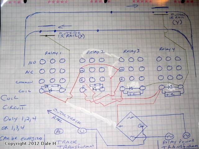
To do this we need 4, 3PDT 10 amp relays. Below is a sketch of a passing siding with 2 turnouts and shows the relay coil circuit. For simplicity only the center rail is shown for the pattern and the loop connects in whatever configuration desired. A separate transformer is used for relay power so only one bridge rectifier is needed. The minus of the bridge rectifier shares a common with the U terminal of the track transformer. If a tap is used from the track power transformer it could be done also with a bridge rectifier to each 12 or 24 VDC relay. For this hookup see my post on using relays for accessory activation. A diode is placed across each relay coil as shown for spike suppression and a capacitor 470 uf 35 volt is also across in proper polarity to eliminate relay chatter when the outside train wheels complete the coil circuit. Relays coils 1 and 2 are activated by outside insulated rail X. Relay coils 3 and 4 are activated by outside insulated rail Y and both are as long as the maximum stopping distance when power is removed or reduced to the oncoming train. A corresponding center rail is also insulated as well as Insulated center rails X and Y are the same lenght as the outside one. Following each is an additional insulated center rail (X behind) and Y behind). These are as long as the longest train to be run. The function of these will be explained later. Note that the relay power for relay 3 coil is in series with the NC (normally closed) contacts of relay 2 and relay coil power for relay 2 is in series with the NC contacts of relay 3. (left set of contacts ,relays 2 and 3) This prevents both relay coils form being activated at once. Which ever train arrives first or is left on the block will be on. When both blocks X and Y are occupied, either relays 1,2 and 4 or 1.3 and 4 will be on but 1,2,3, and 4 can not be activated together as relays 3 and 2 lock each other out.
 |
Below is the wiring for the center rail track power.
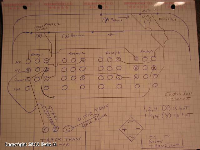 |
If relays 1,2 and 4 are on Center rail X is hot and center rail Y is off. If relays 1,3 and 4 are on Center rail Y is hot and center rail X is off. This circuit is the left set of contacts,relays 1 and 4. The right set of contacts,relays 1 and 4 is used to disconnect X behind and Y behind respectively from track power and connect it to X center and Y center when blocks X or Y are occupied. This allows for shorter stopping distances and eliminates roller jumping of X and X behind. As soon as power is cut to blocks X or Y,the whole train,not just the engine will get zero or reduced power. The NO contact of relays 1 and 4 can be used to circuit reduced power to the stop block. In this drawing Tap B of the transformer is set at around 5 volts,stall power. This will allow for more gradual stops and leave enough voltage to keep the lights on the stopped train. This will increase stopping distance so if this optional circuit is used the blocks need to be sufficiently long. The right contact set of relays 1 and 4 prevent transformer taps A and B from ever being connected together. Note: The left contact set NC terminal relay 4 goes to B tap of the transformer. It can be connected to the left contact set NC of relay 1. This was not drawn in to simplify the drawing. Also note stopping voltages and characteristics can vary greatly between engines,so a median voltage must be kept to avoid collisions.
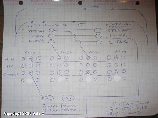
The last drawing is the circuit used to throw the turnouts in the proper direction. The center set of contacts of all 4 relays is used to do this. This drawing assumes that the turnouts can take continuous voltage without damage. Other types such as Atlas can be thrown safely with capacitor discharge.
 |
So in the loop drawn the trains can be made to go in opposite or same direction and will alternate when they are both on the passing siding. So if blocks X and Y are occupied,the train that was there last will proceed. So if relays 1,2 and 4 are made Train at X will leave the loop and return to X. When it leaves,relay 2 will drop out and relay 3 will come on since Y is occupied and the lock from X is broken. When it returns,relays 1,3 and 4 will be energized ,the turnouts will be thrown in the proper direction and the train at Y will make the loop. (Y behind) will have track power as the train enters the block but when it reaches Y block it will disconnect from the track power and connect to whatever power Y has.
This circuit will be very mechanical in operation. As soon as one train leaves,the other one will start,so it is not so realistic. With 3 more relays and a timer a time lag can be set so there is an interval between when a train arrives and departs. I will describe this circuit later if there is any interest. With some more relays and a timer, a soft start circuit can also be added to make the automation more realistic.
Dale H
