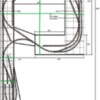
Here's a diagram of my current layout:


1-17-15 CURRENT LAYOUT


Currently I have a single pair of wires going to the layout under the left side at the Wye.  All my components (PH180, TIU, Command Base1-L) are also underneath the table at the Wye.  There's no isolated track as of now.  I do have a few jumpers around the layout, but only to ensure current is getting to certain spots.


I'm having a bit of trouble when there's an engine sitting on the siding on the bottom right (says 54", that's my small downtown area).  With an engine there and engine(s) sitting in the "yard" on the lower left side), more times than not the engine on the right starts up whenever I turn power on to the layout.


I want to re-wire the layout to see if it will solve this issue.  I bought a MTH terminal board but I'm not sure where to place it under the layout so I can star-wire everything.  I've also got 4 toggles I want to use to turn power on/off to the leads coming off the turntable.  I have the toggles mounted on the angled fascia near the engine house above the TT.


The only real obstacle to re-wiring is at the Wye.  The access to the middle of the layout is at the Wye and is a drop-down section.  There's always a work-around so if I need to I can run wire under that section and simply use a plug that needs to be disconnected whenever I have a need.


I was even thinking of running a pair of wires to that area of track now (without re-wiring) just to see if that solves the problem.


Any ideas?

Attachments

Images (1)
  • 1-17-15 CURRENT LAYOUT
Original Post

Replies sorted oldest to newest

Bob, Interesting thread. My first thought is you need to deal with the two different systems. TMCC/Legacy and DCS.  Apparently the lack of signal, conventional start-up applies to both TMCC and DCS??  There are different corrections for both systems' problems.  IMO. 


Keying on the curved siding mentioned.

(1.) TMCC/Legacy may require the installation of a ground plain wire.

(2.) DCS problem may deal with the open-ended track, requiring a magic light bulb or end of line resistor to inhibit signal interference.  DCS problems also seem to relate to the version of the TIU unit. 

That's a start, I am by far not the expert  in either operation system.  You may want to post this to both the TMCC/Legacy forum and the DCS forum.

Last edited by Mike CT

Mike,


Thanks, most of the time it only involves 2 or more PS2 engines, but I also have periodic issues if I have PS2 engines on the layout and place a TMCC engine on to run.  Usually, but not always, 1 of the PS2 engines will start when I apply power to the layout.


My TIU is a L, latest software version.  I can remove the TMCC engine and it seems to fix the problem, but if it's all PS2 engines I haven't noticed if it's a specific engine or a specific spot on the layout.  A couple of wire extensions to that right side may solve the problem.


How would you "star-wire" this layout?

Originally Posted by Bob Delbridge:

Mike,


Thanks, most of the time it only involves 2 or more PS2 engines, but I also have periodic issues if I have PS2 engines on the layout and place a TMCC engine on to run.  Usually, but not always, 1 of the PS2 engines will start when I apply power to the layout.


My TIU is a L, latest software version.  I can remove the TMCC engine and it seems to fix the problem, but if it's all PS2 engines I haven't noticed if it's a specific engine or a specific spot on the layout.  A couple of wire extensions to that right side may solve the problem.

There has been discussions about the two systems and adding blocking inductors, (RF choke coils), to certain TMCC/Legacy locomotive engines/units to solve the problem you have detailed.


You have (4) DCS circuits available, one TIU. You can switch the two variable circuits to fixed, which works well for the Fort Pitt High-Railers layout.

(1.) One DCS circuit, Fixed1, Your exterior loop.

(2.) One DCS circuit, Variable1, programmed to Fixed, partial interior loop and sidings.

(3.) One DCS circuit, Fixed2, left side of bridge and partial sidings.

(4.) One DCS circuit, Variable2, programmed to Fixed, for the TT and spider tracks.


That wiring set up would give you the maximum signal generation with the equipment you have, IMO.


Some recommend more DCS circuits for a TT/Engine Storage area.  


One other note, DCS can be troublesome with loops, open end the loop with your wiring, It may or may not work better that way as oppose to the loop being completely connected end to end.


Last edited by Mike CT

Thanks again Mike.


I'm going to run some tests using my engines to see if it's a particular engine or if it's on a particular area of the layout, or a combination.  I'm fairly sure it's in 2 areas of the layout (the newly added TT and yard seem to be causing some problems as well as the siding I mentioned), both are points are at the end of the wiring (from the TIU) as far as wiring goes.  I can't recall ever having problems anywhere else on the layout.

There is a known problem with TMCC engines and lighted cars that been reportedly solved with a 22uh choke installed in the power wire from the pick-up rollers to the TMCC boards (or lighting for lighted cars) may solve the problem. You might try that first.


Also the DCS signal will run back over itself when going around a loop of track if there is no isolation point anywhere in the loop to prevent that from happening. It has been reported that this can cause problems as well.


I never did this on any of the temporary layouts I had before starting the more permanent one I have now. They were all just small loops of track maybe 4 to 4-1/2' x 7' to 8' and I didn't think it was needed. I had occasional problems with engine's not being found, not on track, disappearing etc.


I have wired my current layout which is 6'x16' following Barry's book as closely as possible and those problems no longer exist. I have 10's everywhere on the layout and no problems at all. I could not believe the difference this made. I am using the same DCS system and Powerhouse 180's I had before. My DCS system is also a Rev L. I don't have any TMCC engines, but I do have Legacy and one Legacy engine all connected to my layout with DCS. They both work very well together.  


Although it would likely be a good idea to re-wire your layout by 'The Book' using terminal blocks and then feeding isolated track blocks, you might see some nice improvements by trying the isolation and chokes first? Might be worth a shot.

rtr, thanks.  I've been looking at "the book" today and think I know how to go about re-wiring this.  I was going to use some CAT-5 8-wire cable (twisting 4 wires together to make each leg) I had but seems I don't have quite enough so I need to go ahead and buy a roll of 14 or 16 gauge wire.  The room is 11x12 with that 2x10 yard extension down the left side.  Probably 1/3 scale mile around the loop.

I would recommend OGR wire available in #14 and #16 (I would not use the cat-x wire for track power). OGR wire is perfect for wiring by 'the book' for a DCS system and very nice wire on top of that, easy to work with as well. I used it, #14 to terminal block and #16 to track blocks, and it worked very well for me. I also used the MTH terminal blocks, they are also very nice and make for a nice wiring job. I ended up liking the 24 terminal blocks the best as the power and common go up and down each side instead of power on one side and common on the other like the 12's.


Which track and switches are you using?


I ask because you do have to insulate "blocks" or sections of tracks from one another. That may be a pain.


Also, I ask about the switches, because many switch motors do cause interference to the DCS signal which is remedied by the 22uh choke previously mentioned.


It would also appear that running one hot and daisy chaining that to the other toggles hot would not be a problem.


I have also read some of Barry's posts that dispel the myth of "equal lengths of wire".

You can locate the terminal board at the current power and control location and run the feeder pairs from there.


Based on Barry's recommendations for length's of the power divisions or blocks, cutting the main area into a quadrant would come close and cutting the yard\TT leg in half would probably be good due to the amount of track in a small area. (pic attached)


Rewiring with the heavier gauge wire in the "star pattern" should solve the issue. If you have other signal issues after that, then the chokes may be needed on the switch motors.

Attachments

Images (1)
  • 1-17-15 CURRENT LAYOUT power division areas
Last edited by Moonman

I ordered some OGR wire this morning.


Carl, I'm using Gargraves track with some Ross track and all Ross switches with Z Stuff switch machines (DZ1000?).


You can locate the terminal board at the current power and control location and run the feeder pairs from there.


That's what I was thinking.  I'll be using on/off toggle switches to isolate the TT tracks so I can park engines there.


Your diagram of chopping the layout into quadrants makes sense and should be easy to do, thanks

FWIW, I currently have one DZ1000 running off track power with DCS and Legacy and it hasn't caused a problem. I only have the one though (very nice too, I might ad). All my other switch machines are Atlas, about a dozen of them, currently on track power also and no problems there either. I am eventually switching the Atlas machines to a separate DC power supply, however, I am not sure the DZ1000 will work with DC? I think it might, but need to find out first, to prevent releasing magic smoke. 

Each quadrant should be about ~10'-11' on the outer loop and less on the inner loop, so close enough for a block. A few for the sidings and you should only be using about half of the terminal with the rest for the bottom legs of the wye and the yard.


So, 8 points to isolate the center rail in the main area and then the yard lead, spurs and TT tracks.

I'm having "Double B" (brain blockage) today, so I have a question.


If I connect FIXED 1 to my main loop and FIXED 2 to the "yard" trackage below the bottom switch on the Wye (where Carl marked as a block on the image in his post, next to the engine house box shown on the plan), what happens when an engine coming off the main loop down the left-most track crosses that point?

Answer to your question: Nothing if both channels are on at the same voltage.


I am thinking that you only need Fixed 1 for this layout.


The diagram was selecting points to insulate and create blocks to maintain good signal and run power drops from the MTH terminal.


Then control the yard(s) and spurs(in main area, if needed) with toggles. On\off in

series with hot from the terminal block. Make the track connections for each block away for the last connection at the end of the block.


Now enter MikeCT's proposal for managing the DCS signal (improving) by using the four outputs of the TIU by further dividing the block section by it's signal source. Then add On\Off toggles where needed.


If you wire and use the simple approach and incur signal issues, you have MikeCT's options as a solution with no major wiring changes. The track will already be divided into blocks with feeders. You could also have the option of adding "magic bulbs" or Susan Deat's device first if you incur signal issues.


I'll read the entire thread again and see if it make sense.


Even better, try your thought of running one pair of wires to the troublesome area first and see if that solves the issue. If it does, then you just need to configure your toggles.


Why go hog wiring wild when the layout almost works perfectly with only one set of feeds? Go from fixed 1 to the terminal board. Connect your existing pair. Create a second pair and connect to the area of concern. Test.


Should work well for speakers too, or save it for future layout additions.


Glad it all worked out and you have improved DCS signals and operations. I found that the wiring guidelines Barry prescribes really do make a difference. Sure did on my layout, mine is now the best I have ever had with all 10's as well. I haven't even had a 'check track' or 'engine not found' on my new and properly wired for DCS layout. Legacy works great too. Makes everything more enjoyable that way.

Thanks guys!


Carl, I took the existing single pair of wires and moved them to the drop-down bridge, then the MTH terminal board.


After making most of the cuts you recommended (the drop-down bridge was isolated anyway), I then ran wires from the terminal board to the 4 Turntable tracks.


Another pair of wires was run in between the 2 switches on the upper left side (at the 24" measurement on the drawing, that was another cut in the middle rail).


The final pair was run up to the northeast corner of the layout.


Total of 7 pairs of cables off the terminal board.  I have more room if I want to add more wiring, but right now it's working fine.


I might add another pair just east of the drop-down bridge, but that means I have to drag a bunch of stuff out from under the layout and drill holes to route the wires.


After tearing/rupturing my right cafe muscle Saturday morning (63 yr olds don't need to be doing jumping jacks and running in place ), I gave out pretty quickly today.


I amazed myself by not getting any wires crossed in the process.  I thought 3 out of 4 STSP switches were faulty, but once I toggled them a few times they worked fine.


Now I can get back to the 5-6 projects I have going on!  2 cabooses, 1 engine, 1 boxcar, 1 bulkhead flatcar, and as soon as my rollers come in from Crest, a test stand.

That's a beautiful thing!  Do you have the newer TIU?


I like wyes. I always liked your layout because of the wye and the TT at the end.


So, now you can control the yard, too. All is well on the Southeast & Virginia RR.


I officiate b-ball and keep my conditioning up for that, but five years ago, I thought I could scrimmage with my daughter's team. Planted to drive to the hole and had a flat. Tore the calf muscle and went down. 6 weeks to move ok, 6 months before I had strength again. Check out sports medicine searches to rehab the muscle. The universities publish some good stuff. It works. if you don't rehab, it will drag on.

Last edited by Moonman

Thanks Carl,


I like Wyes and TTs too.  Every layout I've had since my first has had a Wye.  I wish RCS made an 090 Wye!


If I could ever clean out the rest of the upstairs I could double the size of my layout mainline plus add 1 or 2 more industries.


Good tips on the rehab.  I work part time at 2 golf courses and get to play at both free so at least I'll be getting some walking done.

Add Reply

Post
The Track Planning and Layout Design Forum is sponsored by

AN OGR FORUM CHARTER SPONSOR

OGR Publishing, Inc., 1310 Eastside Centre Ct, Suite 6, Mountain Home, AR 72653
800-980-OGRR (6477)
www.ogaugerr.com

×
×
×
×
Link copied to your clipboard.
×
×