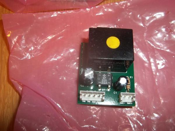
I am looking for a wiring diagram for a TAS Smoke Chuff board. It is a first gen version unlike the latest Puff-N- Chuff board. See photo. Thanks, John
Replies sorted oldest to newest
Connectors look like they are marked. G
Never saw that one, ask Mike Reagan (Mikado on OGR), if he doesn't know, you're probably out of luck. ![]()
GGG said, "Connectors look like they are marked. G" G, yes they are marked (TRK - TRK - SMK - SMK) below the 4 pin plug with OUTPUT above the plug. The two pin plug is marked (SMK- SMK+) . I can make some guesses but they would be guesses. I'm more worried about the other boards in the loco and the motor in the smoke unit, than this chuff board. So before I start guessing I thought it prudent to see if I could find the actual wiring diagram. J
Kerrigan, Thanks for your trouble but that is a Cruise Commander board and I need a diagram for a Smoke/ Chuff board. It is used in conjunction with a Cruise Commander or an AC/DC commander I did save your diagram for future reference. Thanks again, John
Track power are the 2 TRK, The 2 Smoke are to heat element. Last is smoke fan. + and negative. + to rotate fan CW; It will be a 3-5VDC output. G
I'm curious, if this is a "chuff" board, where is the input chuff signal in that mix? So far I just see a power board for continuous running of the smoke!
John, no chuff input that is what I was puzzled about. Would you need a 12V relay for a power only board ? I need to pull the mount tape off the back and trace out a schematic. J
I have no idea what that board is supposed to do, but it sure doesn't look like the TAS puff-n-chuff board.
John said, "sure doesn't look like the TAS puff-n-chuff board." Ya ![]() Think ! I traced out a schematic last night photo attached. The relay will pick up at 6v 46ma so I can switch it with a reed switch and power it with the 6V headlight regulator from a PS-1 loco. I would have a set of contacts for the fan and another for the chuff input on the ERR CRUISE COMMANDER. If you have any thoughts I would like to hear them. I think the fact the input for the relay is marked +smk and -smk yet it goes straight to a bridge rectifier is interesting. If it took power from the smoke output from most of the TMCC boards I know of, is that not half wave DC might the capacitors and the bridge be to keep the relay from chattering. Does look like a simple on / off for a diesel smoke unit. I'm going to see how many cycles it can do as a chuff / fan switch before the contacts fry. J
Think ! I traced out a schematic last night photo attached. The relay will pick up at 6v 46ma so I can switch it with a reed switch and power it with the 6V headlight regulator from a PS-1 loco. I would have a set of contacts for the fan and another for the chuff input on the ERR CRUISE COMMANDER. If you have any thoughts I would like to hear them. I think the fact the input for the relay is marked +smk and -smk yet it goes straight to a bridge rectifier is interesting. If it took power from the smoke output from most of the TMCC boards I know of, is that not half wave DC might the capacitors and the bridge be to keep the relay from chattering. Does look like a simple on / off for a diesel smoke unit. I'm going to see how many cycles it can do as a chuff / fan switch before the contacts fry. J


