Hey All,

I have no room for a permanent layout until we move in a couple of years and want to have something up for now.   What would you guys think the best size and construction for a portable/temporary layout would be?

I thought about 5x9 and use sound deadending like homasote or an equivalent and need to make it somewhat manageable to move and store.

Thanks in advance.

Last edited by Kelpieflyer
Original Post

Replies sorted oldest to newest

Hello Russell,

Asas soon as I saw your topic and the reference to a ping-pong table, I thought of this video:

https://m.youtube.com/watch?v=xMQojxGdBN0

If you can get past the "cringe worthy" part where his able assistant is helping to move the layout while in stocking feet, this shows a simple, but clever, traditional American Flyer layout in a form that can be temporary, and even allows the table still to be used for table tennis when so desired.

Here are a couple more videos of the layout in use:

https://m.youtube.com/watch?v=RfHwk_aJ5Hs

https://m.youtube.com/watch?v=meXdlZx6XW4

Hope this gives you some ideas.

Cheers!

Alan


If it interest you, Classic Toy Trains (gasp - an OGR competitor!) published the following track plan for O scale that fits comfortably on a 5'x9' surface and I imagine could be replicated faithfully in S scale.  I originally built a compressed version on a  4'x8' that I cut in half and reattached with a 4' hinge, allowing me to fold it up and lean it against a wall when I needed the space for something else.  I'm now rebuilding it in modular form for ease of transporting to METCA's semi annual train meet.

http://ctt.trains.com/rapid/20...-this-retro-railroad

Firewood posted:

Just a suggestion, but if you can squeeze in an extra passing loop, it will let you set up trains or switch in the yard and allow a train to do laps on the outside without interference. Please excuse the rough-and-ready sketch.

layout

Is there a way to wire it this way if Im only running conventional?

AmFlyer posted:

Nice layout plan. One thought about the 751A Log Loader placement. When I have used this accessory on my past layouts it added more operating possibilities if a track is also at the rear of the log loader. This allows the 714 log unloading car to remotely unload logs onto the 751A.

Never thought of that.  I'll have to work that in somehow.

Building the layout for 2 transformer operation is easily possible. I would have the outside loop and the passing track at the log loader on one transformer. The yard, lower passing track and the connecting loop back to the divergent side of the turnout at the log loader would be fed from the second transformer. Whenever possible feed power to the point rather than the frog side of Gilbert turnouts. It reduces and simplifies the wiring and the need for fiber pins. All turnouts should be set to 2 train operation.

To do that put a short, about 3" long piece of track between the turnouts on each side of the outer loop. Feed transformer one power at those two points. Similarly put a short piece of straight track between the two back to back turnouts at the yard entrance and connect transformer 2 power there. That is all you need. I think you may also need fiber pins in the base post rails of the 2 inner loop tracks colored purple on the drawing.

It looks like this is optimized for counter clockwise operation. I count 8 places for uncouplers. By the way, the layout as now drawn is 60" wide so it will barely fit on a 5' wide board. Definitely too big if you add the 3" pieces of track I suggest.

Unless I am missing something from the track plan, which looks very by the way, it will not lend well to a ping pong table unless you make several adjustments to allow for the table to be folded in the middle.  Since you have stated that you are planning on keeping this layout out in the garage, depending on how your walls are constructed, possibly a Murphy bed style of layout/table would better suit your track plan.  In case you are not familiar with a Murphy bed, it is one that folds up flat, parallel to the wall.  There is a gap between the wall and the layout therefore scenery could stay on the layout.  Murphy bed hardware can be purchased through places like Rockler Woodworking.

Kelpieflyer posted:
Firewood posted:

Just a suggestion, but if you can squeeze in an extra passing loop, it will let you set up trains or switch in the yard and allow a train to do laps on the outside without interference. Please excuse the rough-and-ready sketch.

layout

Is there a way to wire it this way if Im only running conventional?

I think you could isolate the inner oval from the outer one to let you run the yard separately. Standard two-throttle cab control with center-off switches would do it. The extra passing loop options should let you swap trains that you made up on the inner loop for those coming off the outer loop into the yard.

Russell, I think you will find building this as a modular layout will prove to be a lot of work. Lionel "O" gauge can be a lot simpler since track switches and many accessories can use track power. In "S" that is not the case. If you put in the 8 uncouplers I recommended but no additional accessories like a billboard whistle, switch tower, semaphore, or street lights there will be 57 conductors running from the control panel area out to items on the layout. When Lionel owners would look under one of my Gilbert layouts they were always surprised at how much wiring there was. I have built over 40 different Gilbert layouts for myself, all between 5'x8' and 6'x10', none were modular for basically this reason. It was at least for me too much work to build it, followed by extra work to disassemble then reassemble the layout modules.

Next step is to mock up the track to verify fit and operation, then start building. Have fun with it!


AMFLYER (Tom) - thank you for the experienced insight!

Russell - based on Tom's wiring information, it would seem a modular layout would be difficult. The problem could be solved by fabricating two wiring harnesses - one for track power and one for accessory power. Using a combination of D-Sub connectors and Anderson Power Pole(for track, heavy gauge wire) one could build the harnesses with the accompanying attachment connectors from the transformers.

All of that seems a bit much for what you want to accomplish.

Item#2 - the CTT plan is O and has a reversing track on the inner loop. Again, you don't want to go there for this project.

Item#3 - some SCARM help - in Tools -Toolbox or the icon on the menu bar there is a rectangular baseboard tool. I used it to create a rectangular baseboard with exactly 60" x 108". View - Show size and area.

Item#4 - In the library panel there is a figures library. I used the rectangle figure  and created 4 - 30" x 54" rectangles, set the Vertical position at -.25" and the height at  .20" and selected Translucent for the color. Then, copy and paste three more and move them to position.

Now you have four outlines that would represent each module.

This will enable you to see were the breaks for the track are located. The current layout would need some repositioning of switches.

I would suggest a two line layout that doesn't have the lines joined or keep the plan that you have and tweak it for the modules . It will greatly reduce the wiring and potential electrical issues. 

I have attached your first attempt with the modules outlined. You can use the file and rename it with each layout change to keep the modules.
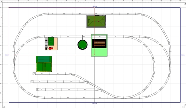
Flyer Temp Layout Modules

I also found a 60" x 90" track plan from a 1953 book that sets up nice for accessories. See attached. The spur at the bottom looks like it may work for log loader.

Attachments

Images (2)
  • Flyer Temp Layout Modules
  • AmFlyer_60_x_90_Track_Plan
Files (1)
Last edited by Moonman

What brand of track and switches are you using?  If you're using pure AF tracks and switches then you're ladder (switch yard?) won't work correctly.  I tried replicating your original layout with RR_Track and the switch base causes a problem coming off the main. The switch base touches an adjoining track. I put in a 3 inch extension and the switch base doesn't touch the main.

Steve

My comments on wiring and layout size were focused on the expanded layout proposed by Firewood. The original layout is smaller and fits fine on a 5’x9’ board. Steve is of course correct that the Gilbert switches cannot be stacked w/o a short piece of track between them. To fix this I would make the first yard turnout a RH and have that siding go up towards the log loader. That would also eliminate the S curve in the yard. 

I like that it is right-hand running or counter-clockwise. Just a preference of mine, although I think the HO guys like it that way with outside rail hot.

I created some modules to check the track breaks. If you make the right side smaller, you can cut the track break right at the switch joints and leave them attached to the module. Then, split the difference with the other two and the break falls on tracks that can loosened and removed.

3 sections ~36" x 66"

Attachments

Last edited by Moonman

Add Reply

Post
The Track Planning and Layout Design Forum is sponsored by

AN OGR FORUM CHARTER SPONSOR

OGR Publishing, Inc., 1310 Eastside Centre Ct, Suite 6, Mountain Home, AR 72653
800-980-OGRR (6477)
www.ogaugerr.com

×
×
×
×
Link copied to your clipboard.
×
×