@cjack posted:I’d like to just order the B joiner, why the special telephone request?
This and the "terminator". Just list them in the parts or in the catalog. I agree I'd like to see these just listed on the parts site.


|
|
@cjack posted:I’d like to just order the B joiner, why the special telephone request?
This and the "terminator". Just list them in the parts or in the catalog. I agree I'd like to see these just listed on the parts site.
Also the part number is 691-JOIN-B00, not B01. But I could only get it to come up with a partial number of 691JOIN
Wonder what the schematic looks like...
@Dave Olson posted:FYI, 691-JOIN-B01 is the B Revision, which has the power supply connector. Revision A did not have the connector.
I'm curious where the support folks that answer the phone are today, I get a recording that I'm calling outside of business hours. ![]()
@gunrunnerjohn posted:I'm curious where the support folks that answer the phone are today, I get a recording that I'm calling outside of business hours.
Maybe they have caller ID. ![]()
Very harsh Marty, but possibly true. I'll try blocking my ID and see if they answer. ![]()
![]()
I think the Joiner looks just like a cable wiring with pins 1,4, and 5 straight thru. And pins 2 and 3 crossed over. Then there is a resistor and LED across 5V which I'm calling pin 1 and GND pin 5.
But the B Joiner has a couple diodes and a power input. A boost of 5 vdc? and what...some protection against back feeding the power?
I have 62 feet of cable wiring on my wifi, ser2, and 6 sensor tracks...so far.
I think the four CSM2 boxes I have strung out after the SER2 and WiFi are probably degrading the power. It appears that the PDI BUS JOINER is really a power tap to power the additional devices. Probably the six boxes I am already powering are as much as the SER2 power brick can handle. If I had a schematic of the board, I could build one for myself, it appears it just injects power to the boxes down the line. I am guessing the two diodes are reverse polarity protection, but that's just a guess.
Back in September of 2016 when my layout was near completion but with a non working LCS, Rudy Trubitt and Jon Z built a mockup of my LCS in their lab. They confirmed the voltage was down to about 2.5V after the 8th device and 50' of cable. The final install I have with 5 of the powered joiners was as suggested by Rudy and Jon and the LCS has always worked.
The function of the Joiner is to bring the voltage back to 5V and provide additional power to supply devices downstream of its location.
Well, I guess that's the first thing I need to obtain in order to get my IRV2 boxes working and use my sensor sleds.
One more thing. The problem was not 8 devices and 50' of cable. If the connecting cable to the rest of the LCS was unplugged from from the 8th device the first 8 LCS devices worked sometimes. Taking off the 8th device, the first seven worked all the time. When the remaining 35 LCS devices were reconnected nothing worked. For the whole system to work with 100% reliability, 5 joiners were needed.
John, I hope that solves your issue, it is an easy fix if it does. I have no IRV2's since they did not exist back then, I just have three of the original sensor tracks with home made cables to remotely mount the control circuit boards from the under-track detector board.
I sold all my original sensor tracks since the IRV2 was available. I have two IRV2 boxes and six of the sleds. I want to get all this working, but there are still roadblocks. ![]()
I'll probably put the joiner at the panel where the six devices are and drive the two or three remaining remote LCS boxes with that power.
@gunrunnerjohn posted:I sold all my original sensor tracks since the IRV2 was available. I have two IRV2 boxes and six of the sleds. I want to get all this working, but there are still roadblocks.
I'll probably put the joiner at the panel where the six devices are and drive the two or three remaining remote LCS boxes with that power.
Using the WiFi monitor program you can see the voltage at the module in question. Might be worth a sniff.
When I plug the cable to the IRV2 in, everything stops working, including the WiFi. However, it might be useful to see what is going on with the existing modules, I forgot about the voltage reading.
I bought an IRV2 just because I didn't have one, and just now plugged it in to see if it's gonna work. I didn't program it, but all seems normal on the system. Yours must be a direct short or something. Check the 5 volts across the connector pins and see if it's affected or some such...pins 1 and 5. Seems like if your wifi goes dead, you're not going to see the LCS come up.
Well... One of them is bad. It's not a direct short, because it lights up and the traffic LED blinks as I spin the remote wheel. For some reason I was having similar issues with both boxes, but now the second one is working as it should. So, I guess I'm going to have to get this one replaced, another PITA!
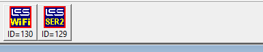
One odd thing happens with the WiFi Monitor, it shows boxes I don't have, and even tries to give me status of them.

I don't have an STM2 or a BPC2. However, I have four CSM2 boxes, and they don't show up at all!

I was hoping it was something simple and I could just fix it and not waste time getting it replaced. That ain't happening as it turns out! I have to suspect this was not tested prior to shipment! I was tempted to try cleaning all this off to see what it looked like, but resisted and just put it back together.


@gunrunnerjohn posted:Well... One of them is bad. It's not a direct short, because it lights up and the traffic LED blinks as I spin the remote wheel. For some reason I was having similar issues with both boxes, but now the second one is working as it should. So, I guess I'm going to have to get this one replaced, another PITA!
One odd thing happens with the WiFi Monitor, it shows boxes I don't have, and even tries to give me status of them.
I don't have an STM2 or a BPC2. However, I have four CSM2 boxes, and they don't show up at all!
Wonder if the CSM2s and IRV2s weren’t available yet to be part of the application. Odd about the BPC and STM. Unless it shows all possible modules but then again I don’t see an ASC2 listed either.
It's odd, that's for sure. I can unplug all the modules except for the SER2 and WiFi, those don't show up then. Maybe it's because I haven't wired, my CSM2 boxes to the switches yet, and it's confused about what they are?
They come back with all the CSM2 boxes and the IRV2 connected. There are four CSM2 boxes connected and one IRV2 connected. It looks like the IRV2 shows each track sled, I programmed the one I have installed so far at #90.

Now I'm wondering if some of the CSM2 boxes are dead as well. ![]()


@MartyE posted:Wonder if the CSM2s and IRV2s weren’t available yet to be part of the application. Odd about the BPC and STM. Unless it shows all possible modules but then again I don’t see an ASC2 listed either.
The Wifi Monitor LE shows all, and only, the LCS modules I have, included my IRV2's.
I think maybe I have more modules to verify if they're working, I have to get those wired...
@Keith L posted:The Wifi Monitor LE shows all, and only, the LCS modules I have, included my IRV2's.
Thanks Keith.
@AmFlyer posted:One more thing. The problem was not 8 devices and 50' of cable. If the connecting cable to the rest of the LCS was unplugged from from the 8th device the first 8 LCS devices worked sometimes. Taking off the 8th device, the first seven worked all the time. When the remaining 35 LCS devices were reconnected nothing worked. For the whole system to work with 100% reliability, 5 joiners were needed.
35 LCS devices? Wow - Lionel's special cable supplier loves you!
Nice to hear it can be made work with that complicated of a setup.
Jim
To be precise, it is 35 after the first 7 so the total is 42, plus the 5 Joiners for a total of 47 LCS devices that required interconnecting cables. The system has worked every time for the past five years. Lionel got a lot of revenue from this poor S gauge operator!
Of all the LCS devices, two ASC2's have failed. The failure was the same for both, on startup they would not remember their programming. I could reprogram them for the current operating session but the next time I turned on the layout they would not work. The only issue was the TMCC ID, the rest of the settings were still in memory. I just replaced them with spares, no more device failures in the last 24 months.
Progress, but still a small mystery. Apparently, the WiFi Monitor doesn't know what to do if the boxes aren't properly configured, something that I figured might be an issue. After I configured all the CSM2 boxes, they show up as expected. Apparently, the CSM2 boxes are mis-identified as STM2 boxes in the monitor, probably because they perform a similar function, just for the DZ-2500 switch machines. Finally it appears that the IRV2 shows up for each configured IR sled, so if you have four connected, I presume it would show up four times. I have the one plugged into the first connector, and it must come defaulted to have two programmed.
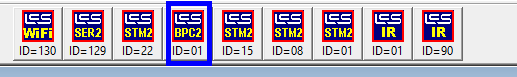
The mystery is still the BPC2 that shows up, I don't have one of those. However, the CSM2 has block power capability, so "maybe" that's one of those showing up. However, I would presume all of them would show up if that was the case.
Is anyone else using the CSM2 boxes? If so, how do they show up in your WiFi Monitor display?

@gunrunnerjohn posted:Progress, but still a small mystery. Apparently, the WiFi Monitor doesn't know what to do if the boxes aren't properly configured, something that I figured might be an issue. After I configured all the CSM2 boxes, they show up as expected. Apparently, the CSM2 boxes are mis-identified as STM2 boxes in the monitor, probably because they perform a similar function, just for the DZ-2500 switch machines. Finally it appears that the IRV2 shows up for each configured IR sled, so if you have four connected, I presume it would show up four times. I have the one plugged into the first connector, and it must come defaulted to have two programmed.
The mystery is still the BPC2 that shows up, I don't have one of those. However, the CSM2 has block power capability, so "maybe" that's one of those showing up. However, I would presume all of them would show up if that was the case.
Is anyone else using the CSM2 boxes? If so, how do they show up in your WiFi Monitor display?
John, the CSM is a combination module, containing BPC2 and STM2 functionality. There were many reason that this was the best way to build and identify the module for the Apps. The WiFi Monitor Tool is useful, and giving you the pertinent information. You can blame me for the design !
@gunrunnerjohn posted:It's odd, that's for sure. I can unplug all the modules except for the SER2 and WiFi, those don't show up then. Maybe it's because I haven't wired, my CSM2 boxes to the switches yet, and it's confused about what they are?
They come back with all the CSM2 boxes and the IRV2 connected. There are four CSM2 boxes connected and one IRV2 connected. It looks like the IRV2 shows each track sled, I programmed the one I have installed so far at #90.
Now I'm wondering if some of the CSM2 boxes are dead as well.
The IRV2 is literally 4 independent IR tracks rolled into one module, with the sled sensors attached to each IR track electronics in the module. So it will show up as 4 independent "IR" in the Tool. Just think of the IRV2 as 4 independent sensor tracks.
Jon,
The WiFi Monitor has proved it's worth to me multiple times, no complaints! ![]() I figured the IRV2 might be handled as individual tracks. I'm a bit more confused about the presentation of the CSM2. I know that the CSM2 has the BPC functionality, but only one BPC2 shows up with the four CSM2 boxes. What happened to the other three BPC2 displays?
I figured the IRV2 might be handled as individual tracks. I'm a bit more confused about the presentation of the CSM2. I know that the CSM2 has the BPC functionality, but only one BPC2 shows up with the four CSM2 boxes. What happened to the other three BPC2 displays?
I'm really just getting started with the whole LCS configuration, so I'm bound to have some surprises and questions along the way.
@gunrunnerjohn posted:Jon,
The WiFi Monitor has proved it's worth to me multiple times, no complaints!
I figured the IRV2 might be handled as individual tracks. I'm a bit more confused about the presentation of the CSM2. I know that the CSM2 has the BPC functionality, but only one BPC2 shows up with the four CSM2 boxes. What happened to the other three BPC2 displays?
I'm really just getting started with the whole LCS configuration, so I'm bound to have some surprises and questions along the way.
I would guess that the TMCC ID for the BPC's overlaps. Did you set their addresses to unique numbers?
The CSM2 boxes all have their switch TMCC addresses configured in increments of 7, but after looking in the manual, I see that I have to configure the block power stuff as well for it to show up. Since I'm not using it now, I think that mystery is solved. ![]()
Well, I got the new IRV2 from ModelTrainStuff, and it doesn't kill my network. They turned around that RMA light lightning!
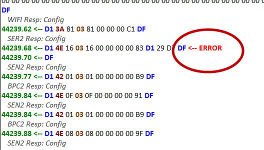
That being behind me, I'm back to figuring out the system. Ran into a little issue, it seems my SER2 box is kicking back an error.
I have no idea what this means, and I don't find much in the way of clarification. Is this something that is "normal", or should I be looking for trouble?
The NVM error looks a bit ominous, not sure what that means. I'm presuming that's Non-Volatile Memory. Is this just because it's not initialized or something else?


I have DZ2500 switches, hooked up to a LCS CSM2. The serial data is connected to a DZ2001 data wire attached to a SER2. For some reason the CSM2 serial data was hit or miss. This setup works every time thanks to Gunrunnerjohn's advice. I can change turnout positions on the LCS app and it shows the correct position however if a switch is changed by a derailer or by hand the LCS doesn't update that information. Is there something I am missing or do I need another LCS component? Thanks, John
@PRR1644 posted:I have DZ2500 switches, hooked up to a LCS CSM2. The serial data is connected to a DZ2001 data wire attached to a SER2. For some reason the CSM2 serial data was hit or miss. This setup works every time thanks to Gunrunnerjohn's advice. I can change turnout positions on the LCS app and it shows the correct position however if a switch is changed by a derailer or by hand the LCS doesn't update that information. Is there something I am missing or do I need another LCS component? Thanks, John
The CSM2 should have the ability, if connected correctly, to update the switch position on the LCS program. It's built into the module. I am not familiar enough with the CSM2 to help troubleshoot this as I use the STM module for my switch positions from FasTrack switches.
That being said the CSM2 module should be able to do what you want.
Exactly how do you have the CSM2 wired? All you should need is the green wire from the DZ-2500 to the sense inputs of the CSM2. As mentioned, I don't use the serial data out of the CSM2 due to initialization issues. I am using the CSM2 Breakout Boards in my installation, but that shouldn't change things.
I used the yellow wires from the dz2500. If I change positions on the app it works. If a switch is changed by derailed or by hand it does not show on the app. I am not using the breakout boards, I wonder if that’s it.
It sounds like it's not seeing the CSM2 status. I don't know why the yellow wire wouldn't work, but did you try the green wire?
No I didn’t try that yet. I will give it a shot. Thanks
Hi All, a shout out to Jon for continuing to reply to questions.
I have not been allowed to have a train layout for more than 10 years. I have moved from that "not allowed" to 9 by 8 bedroom and attached bathroom. I can't fit much of a layout under the bed.
Despite this, I have been purchasing LCS and other modules for future use, just can't use them yet.
So to me, the best thing that could happen is for Lionel or a former development person to form a small team to author a book describing all the modules, their specifications, program requirements, address requirements, capabilities, wiring diagrams, typical small medium, large layout diagrams, etc, so they are documented in a format for raw new users to understand, to also include in depth information for people as gifted as gunrunner John, and others. The command structure, mnemonics, for ALL abbreviations, should be included. What commands do should be explained. Glossaries for all the above should exist. Instruction manuals for ALL the possible modules that could be hooked up to the system should be included as an appendix, so they could be referenced when necessary in the text explaining how to use such devices. As a former military member, I learned to hate mnemonics. Still do hate unexplained ones.
I would be happy to help in developing the outline structure of such a book, to insure it appeals to all talents levels, raw beginner to seasoned programmers. I picture this book as a major undertaking, with input from many actual users, to hopefully, one or more members of the development team. I get the impression that most of these developers have been forced to move onto "greener" pastures. Howard would do anything to save a penny on any product, enough said about that! I understand such an undertaking would require a stamp of approval from Lionel for use of copyrighted information, and so forth.
This book would become the bible for TMCC, Legacy, and LCS control of the layout. I would value such a book with a cost of $50.00 or more, and would pay that in a heartbeat. It might even be possible to make a beginner version for a lesser cost. This would be especially true if the 3 ring binder approach were taken. Spiral binding, or even 3 ring binding would be good. I like 3 ring binding, so supplement and correction would be easy to do, like a Heathkit manual, or a stamp album. I know, "What's a stamp album?".
I hope the movers and shakers that are subject experts chime in on this post. so we could find out if it is even possible that we could assemble an internet/zoom meeting based team to begin this project, and get it done. I can think of 2 California based fellows, and 1 PA based fellow, that I would love to see, say, that they would be happy to contribute to this effort. I also say non-disclosure/non-participation contracts/pacts be d____d! I don't know the geographical layout of the development team, but Zoom and the internet can shrink the world.
I've only scratched the surface of where this book could go, and the audiences that might purchase it. It would mostly be a labor of love. There are many print to order professional book publishing companies, so publishing and distribution is already in the bag.
If we were fortunate, perhaps OGR could even act as a fundraiser/contributor/owner?? of such a book.
Like a book, this post could probably use some proof reading! :-)
@donhradio posted:So to me, the best thing that could happen is for Lionel or a former development person to form a small team to author a book describing all the modules, their specifications, program requirements, address requirements, capabilities, wiring diagrams, typical small medium, large layout diagrams, etc, so they are documented in a format for raw new users to understand, to also include in depth information for people as gifted as gunrunner John, and others. The command structure, mnemonics, for ALL abbreviations, should be included. What commands do should be explained. Glossaries for all the above should exist. Instruction manuals for ALL the possible modules that could be hooked up to the system should be included as an appendix, so they could be referenced when necessary in the text explaining how to use such devices. As a former military member, I learned to hate mnemonics. Still do hate unexplained ones.
I suspect that falls into this category. ![]()
I tried the green wire And no change. I put in a call to Aaron at Lionel and hopefully he has an answer. I am leaning toward the idea that I need the breakout boxes because you hook up the green and yellow wires to it, but I want to know for sure before I sink any more money into this. Thanks for the help.
I can't imagine why you'd need the breakout boxes, they don't change the logic of those two status wires.
Sadly, I haven't seen anything happening recently with the LCS system, I was hoping Lionel would keep developing it and expanding it.
The only difference between my setup and yours is you have the breakout boxes. So if the breakout boxes don’t work it has to be a bad CSM2.
Do you only have one CSM2? FWIW, I have four, and one of them was bad, the board looked like a six year old soldered it. I exchanged it.
Unfortunately I only have one. Thanks again for the advice.
If you were to use a 5VDC supply and tickle one of the CSM2 inputs with that, it should display a change in the status of the switch, that will test the CSM2 functionality. It's a simple box really.
You don't happen to have the hot and ground for the power to the CSM reverse, do you? If so, that can cook the CSM2! The common is your track common.
The CSM2 and the DZ2500’s are being powered by 14V on the C posts of my ZW. The track is being powered by the A posts of the same ZW. So track common is the same as the CSM2 and the DZ2500’s. That’s correct isn’t it?
That should work. I just looked at mine as I'm having one switch misbehaving. With the green wire to the CSM2, mine react to any switch change, no matter how it happens. However, I do have one switch that's wired correctly, and the LED's indicate correctly, but it's backwards on the iPad display. I can't correct it's indication no matter what option I choose. I think it's about time to replace another switch machine...
Actually, John, my post implied that I would be happy to be a member of such a team, and perhaps even the project manager! It remains a necessary venture, that Lionel's instruction manuals do not address, and are very deficient in the area of self promotion of the various Legacy/Lion Chief/TMCC to the proper user groups.
@donhradio posted:Actually, John, my post implied that I would be happy to be a member of such a team, and perhaps even the project manager! It remains a necessary venture, that Lionel's instruction manuals do not address, and are very deficient in the area of self promotion of the various Legacy/Lion Chief/TMCC to the proper user groups.
Yep, I see that. It's just that any such endeavor is a significant undertaking, while I like the idea, I'm just not sure something like this will ever happen with a team. Something like the DCS book happened because Barry saw a way to make some money from his knowledge.
John, I found my problem. My wiring was correct, the CSM2 works, and my DZ2500’s are all working. What I had done wrong was configuring the CSM2. I followed the instructions by pressing program on the CSM2, setting the base address, in my case tmcc ID 1 for the first switch, press set, then aux1 for straight then pressed set. Where I went wrong was on the subsequent switches I did the same thing, so basically I kept changing the CSM2 base address. To sync the LCS switch locations I press sw# then aux1or 2 depending what the LCS diagram is showing for that switch then press set. Thanks for all your help.
OK, I have an LCS issue that I have yet to crack. Specifically, I'm using the DZ-2500 switch machines with the CSM2 sensor boxes for detecting switch positions.
For a "normal" configuration switch, that works out fine, they all work like you'd expect. The LCS display on the iPad detects the switch position properly no matter how the switch position is changed. That's great!
I did have to address one issue as to why some of the switches didn't work properly, it turns out the DZ-2500 puts out a position that's dependent on the position of the arm on the switch machine, that makes perfect sense. However, depending on the switch and where the switch machine is mounted, that reverses the polarity of the sensing output lines! OOPS! OK, so you have to use the yellow instead of the green lead from the DZ-2500, then it all works. Problem solved, and those switches all work great now on the LCS iPad display.
Now the problem. On some of the switches, the "out" path of the switch is really the thru route, and the "thru" path is the "out" route. This is not an issue with the DZ-2500, you can swap the sense of the switch in the configuration, all is well, right? Well, it seems there's no way to convince the LCS to properly handle the situation where you reverse the sense of the red and green LED's on the switch machine to accommodate this situation. The result is the LCS display gets all confused about where the switch is, and when you try to change the position on the iPad, you press once and the display changes but the switch doesn't move. Another press and the switch moves, but the indication is incorrect anyway! I tried swapping the sense of the feedback to the CSM2, but that doesn't address the issue. I confess, I'm stumped.
The only way I see to fix this is to actually move the LED's on the switch and not swap the "thru" and "out" sense of the switch. I'm wondering how others using the DZ-2500/CSM2 have solved this LCS issue?
@PRR1644 posted:John, I found my problem. My wiring was correct, the CSM2 works, and my DZ2500’s are all working. What I had done wrong was configuring the CSM2. I followed the instructions by pressing program on the CSM2, setting the base address, in my case tmcc ID 1 for the first switch, press set, then aux1 for straight then pressed set. Where I went wrong was on the subsequent switches I did the same thing, so basically I kept changing the CSM2 base address. To sync the LCS switch locations I press sw# then aux1or 2 depending what the LCS diagram is showing for that switch then press set. Thanks for all your help.
Funny thing, I was going to bring up programming the CSM2, and I thought I might be posting an insult, so I was still thinking about it. ![]()
I would not have taken it as an insult. I obviously interpreted the instructions wrong. Thanks again for helping.
Yep, glad you sorted it out. Now, if you can just fix my last issue with my LCS configuration, we'll be even! ![]()
![]()
Have you hit program on the CSM2 press sw# and match whatever the position of the switch on the LCS then set. When I matched the position on the LCS it worked. I had been matching the actual position of the switch to aux1or aux2 then set while programming.
@PRR1644 posted:Have you hit program on the CSM2 press sw# and match whatever the position of the switch on the LCS then set. When I matched the position on the LCS it worked. I had been matching the actual position of the switch to aux1or aux2 then set while programming.
Yep, I tried changing the sense with the option, that doesn't do it. The only way I see this working is to swap the LED's, that's going to be a PITA with the DZ-2500. You can't program this with the CSM2 program switch, you only set the base address with that.
Isn't there an option with the DZ2500's to change the green to red and vice versa?
Yep, that's how I got them looking right in the first place not considering LCS operation. However, that doesn't do anything about the sensing, so the LCS code thinks the switch is wrong. It's the swapping of the thru and out routes that confuses them. That's the problem that I'm trying to fix. Recent conversations here got me to wiring the rest of the switches to get the LCS app fully functional, that's when I discovered the problem with those switches.
@gunrunnerjohn posted:Yep, glad you sorted it out. Now, if you can just fix my last issue with my LCS configuration, we'll be even!
Not sure if this is your issue...
@MartyE posted:Not sure if this is your issue...
Thanks, but that's not the issue. I did that, but it didn't solve my problem. The problem is I want the DZ-2500 red/green LED's to swap, which is easy to do. And I want the LCS to match them, which seems easy to do as well. However, I can't get all of them synchronized no matter how I try. I've tinkered with both those options and also driving the CSM2 from the green and the yellow sense leads. There's no combination that makes everything work properly.
I believe the jury has rendered it's verdict. There is a bug or omission in the LCS code, take your choice what you want to call it.
If you have a switch that you want to indicate the "thru" route is the curved exit and the "out" route is the straight exit, you can change the switch sense on DZ-2500 by a simple configuration option with the switch button. Switch to green on the indicator, hold the button down for four seconds, and the switch will change to the "out" route and swap the sense of the LED's and the switch commands. To change it back, do the same operation again. Job done, right? When you use the remote or the manual switch button, everything works exactly as you'd expect, select the "thru" route on the remote, and it switched correctly to the reassigned "out" path as you intended, and the green indicator on the switch (and keypad if connected) are illuminated. Ditto for the "out" path that is not the straight exit from the switch, you use the "out" button on the remote or keypad and the switch red LED lights as you'd expect.
Sadly, when you do that, there is no way to make it work properly with the current version of the LCS application. The LCS program simply does not recognize the ability to change the sense of the switch, even though the DZ-2500 and CSM2 hardware would have no problem with it. There would have to be an option to swap the paths in the LCS application to make this work properly, and there is none.
When the switches are configured this way, you can get everything to iPad display properly if you switch them manually with the switch button, or with the TMCC remote. Makes you think it must be possible, right? However, if you use the iPad to switch them, it will change the switch position and color on the screen, but not move the switch. Touch it again, and it will then move the switch and match up the screen with the switch. So, basically, you have to touch the switch twice, ignore the incorrect operation the first time, and do it again to get the correct switch position. I'm sure this is because the LCS program on the iPad sends what it thinks is a "thru" or "out" command to the switch since there's no way to tell it to reverse them.
Right now the only way I see to "fix" this is to physically rip apart the DZ-2500 switches, swap the LED's, and then turn off the option to swap the routes. This is less than desirable as then to get the "thru" route on those switches, you have to select the "out" route. I am bummed that I spent a ton of money on the DZ-2500 compatible products from Lionel, only to find out they don't solve the problems! I have 30 CSM2 Breakout Boards and four CSM2 boxes, and there's no way to configure them properly for operation with a standard DZ-2500 configuration! I'm not sure what the sense is to have all these Z-Stuff specific products build specifically for the Z-2500 but you can't really use them with anything but a very basic layout scheme.
@Dave Olson, any chance there'll be an update to the LCS program sometime in the near future?
Just wondering if Lionel is going to continue to support or add to it. I have not seen much mention of it. I used it on my last layout and am at the point on the new one where I need to decide weather I will continue it or us JMRI with the DCC system left from my 2 rail layout. I am not into automation of trains but would like to control switches and routes from a screen. I like the touch screen feature of the I Pad but JMRI on the computer uses a mouse. JMRI does have support for TMCC. I am using Tortise with machines that will work with both Lionel switch controllers or DCC switch its. The DCC system uses a two wire bus around the railroad that powers the track ( won't be needed) just use the bus to power the switch controllers and deliver the data making them more local and no need for longer runs back to SC2 units or long data cables ( seem long runs are a problem with serial) if spread out. any thoughts from those of you using LCS now. Rick
I have no insight into Lionel's future product plans but I doubt Lionel will abandon the LCS concept. The specific devices may evolve. I use LCS to control my layout and really like it. It has many good features and is simple to install, connect and program.
Some specific items. My layout has the ASC2's and BPC2's located at the items they control, so, for example wiring from a turnout back to an ASC2 is short. The only bus wiring for the LCS is the PDI cable and the power. Multiple iPads can be used at the same time. I have three in use for visitor support, one is a 13" with an Apple pencil, the other two are 10" easy to carry iPads. It is convenient that engines can also be controlled from the LCS iPads although I mostly use Cab2's to operate trains. The LCS operates all turnouts, uncouplers, action cars, lighting and block power. It also has many preset routes that can be actuated with a single icon. It is also easy to spread the layout mimic over multiple screens with the same turnout controllable from more than one screen. I have seven LCS screens to operate the layout.
I would absolutely use LCS again were there a need. The issue at the moment is some components seem to be on backorder.
Lionel says the following about the Base3 and LCS:
"The Base3 includes 3X PDI connectors for the Layout Control System. No longer will you be limited to connecting all LCS modules on a single daisy-chain. The Y-cable will also no longer be needed! See page 240 for LCS product!"
Clearly, Lionel is going to continue to support LCS. Add to it? We'll see.
I do wonder why Lionel is dropping the IRV2. They're working well on my layout.
@Keith L posted:I do wonder why Lionel is dropping the IRV2. They're working well on my layout.
My guess is sales. One thing Lionel is horrible at is promoting the peripheral LCS stuff.
Integral PDI connectors is a major plus. If the Base3 includes a wired Ethernet connection, it would simplify integration with external computer control.
My current Legacy base is connected using the WiFi adapter, it's worked fine. It's great to have the LCS available on my computer anywhere I am. I greatly prefer editing the locomotive data using a real keyboard on a large screen... ![]()
@Tracker John posted:Integral PDI connectors is a major plus. If the Base3 includes a wired Ethernet connection, it would simplify integration with external computer control.
Per the Lionel catalog:
"USB Connection Included USB cable allows for communications connection to a PC. Use 3rd party control software such as the eTrain Command Console. Also use the Legacy System Utility when needed."
I don't want a USB cable to my PC, but I'm hopeful the WiFi will allow this unit to connect to a network like the current LCS WiFi module does. I use that for my LSU on the PC, but I don't need any wires strung for 30 feet from the command base to my computer!
Gunrunner John. I used the iPad on the last layout but thought it was only available for that not a PC or Mac. I would love to have it on a larger screen as well , how did you accomplish this.
@gunrunnerjohn posted:I don't want a USB cable to my PC, but I'm hopeful the WiFi will allow this unit to connect to a network like the current LCS WiFi module does. I use that for my LCS on the PC, but I don't need any wires strung for 30 feet from the command base to my computer!
John, would these help?

GRJ, operate your base in a show where the 2.4 Ghz spectrum is an interference s**tstorm and you'll appreciate a wired connection.
@Rick Rubino posted:Gunrunner John. I used the iPad on the last layout but thought it was only available for that not a PC or Mac. I would love to have it on a larger screen as well , how did you accomplish this.
Sorry, I meant the LSU, not the LCS. The LCS is indeed only available on the Apple platform, another shortsighted move by Lionel. ![]()
thanks for the reply John.. got my hopes up for Mac or PC use. yes I agree they were short sided. I can use my old DCC system for control of the switches but JMRI is another complicated hobby all to itself , the LCS was so easy to set up.
LCS has huge promise, but they seem to have abandoned it. No updates for years, and now they're getting rid of the ISV2, one of the reasons I bought the LCS in the first place! ![]()
I just picked up another IRV2 and one of the add-on sets, I still want to be able to use this functionality.
HI John, what is the ISV2? Where did you find the add on set? I cant seem to find them.
@amtrack5899 posted:HI John, what is the ISV2? Where did you find the add on set? I cant seem to find them.
IRV2, that's a typo. The add-on sets are like hen's teeth.
Please enlighten me. If they eliminate the IRV-2 will manual programming of the engines be the only option? They already eliminated the modules that came with the engines.
Beats me, don't know of any other way to program them, I'm a bit surprised it's on the chopping block.
good question to ask them at April York.
I think Lionel is still selling the Sensor track. The way I got my S gauge Sensor tracks is to buy three of the O gauge FasTrack pieces, remove the components and mount them under my S gauge track. I think if three sensors are needed it costs more to buy the three Sensor tracks to cut them up, but it works. It is convenient to just run the engine over the Sensor track for programming.
I’m a little confused on what direction lionel is heading. To my knowledge the sensor track is the only method for 2 way communication.
I’m building a new layout and want to install LCS, but components like the ASC2 to run my many switches seem to be impossible to get now. Is that just a supply chain issue or a signal that ASC2s are going to go the way of the Cab2? They are still there as part of the LCS system in the latest catalog, so I assume it’s the former, but has anyone heard anything?
I think it is a supply chain issue. The other day when Ryan of Lionel was on YouTube he stated LCS will continue.. The wifi device is now included in the new Legacy base 3.
@Alec_6460 posted:I’m building a new layout and want to install LCS, but components like the ASC2 to run my many switches seem to be impossible to get now. Is that just a supply chain issue or a signal that ASC2s are going to go the way of the Cab2? They are still there as part of the LCS system in the latest catalog, so I assume it’s the former, but has anyone heard anything?
Anything in the new catalog is continuing to be produced. The ASC2 was originally going to be here a few months ago but electronics sourcing has us waiting on a few components. Hopefully we'll get them in a few months.
That is good to know. Fortunately I have a few spare modules in case one of mine fails. The Layout Control System is too good to not fully support.
@Dave Olson posted:Anything in the new catalog is continuing to be produced. The ASC2 was originally going to be here a few months ago but electronics sourcing has us waiting on a few components. Hopefully we'll get them in a few months.
Thank you so much Dave! That is very good to know. I am really looking forward to having LCS controlling my new layout.
@Dave Olson, since the CSM2 and the DZ-2500 Breakout Board is still in the catalog, is there hope that the LCS software will be fixed to properly handle all configurations of the DZ-2500 switches? I'd sure like to get that working right. ![]()
GRJ-
Strongly endorse your request to get the CSM2 "right".
A minor issue related to the CSM2 (although not your specific problem) came to light recently in conversations with Dennis Zander regarding combining the CSM2 and DZ-2001 data wire driver. Why would you have this situation? Well before the CSM2 I was driving the DZ-2500s with the DZ-2001. I had not taken it out of the loop completely after having incorporated the CSM2, and it appeared that they could be used in combination with both driving the switch machines.
My DZ-2001 blew out about 2 years ago and I had just moved the serial wire over to the CSM2. All was well. I just recently came back to looking at this problem and discussed it with Dennis. Regarding the CSM2/DZ-2001 combination, Dennis stated:
"After much discussion with Jon Zahornacky (who designed the Lionel LCS system), it seems that plugging in a CSM2 into the Legacy base causes the date rate to change which screws up the 2001 data line and reception of info by DZ-2500's."
So the advice from Dennis appears to be use either the CSM2 OR the DZ-2001, but not both. Just a note for those of us using the DZ-2500.
Not sure any "change" is required by the CSM2 to correct this specific problem but points to a different handling of serial data signals from the 2 products. CSM2 has been solid for me.
There is another problem with the CSM2 and the DZ-2500. When using the CSM2 to supply serial data, there is a data-race condition. If you power them up at the same time, the DZ-2500 apparently gets scrambled because of something it see s as the CSM2 is initializing the serial data. This happens about one out of every three or four power-up cycles from a cold start. It drove me nuts for about a week before I finally figured out where the problem was. The "fix" apparently is to power up the CSM2 and wait a couple of seconds before powering up the DZ-2500 switch machines. That way the CSM2 serial data is stable and the issues don't come up. It's important to note that powering up the command base, the DZ-2001, and the DZ-2500's at the same time isn't a problem, only the CSM2 serial data at initialization appears to be a problem.
However, the really big problem for me is the lack of correct operation of the DZ-2500 operation from the LCS application. I'm bummed this doesn't work correctly.
@gunrunnerjohn posted:I believe the jury has rendered it's verdict. There is a bug or omission in the LCS code, take your choice what you want to call it.
If you have a switch that you want to indicate the "thru" route is the curved exit and the "out" route is the straight exit, you can change the switch sense on DZ-2500 by a simple configuration option with the switch button. Switch to green on the indicator, hold the button down for four seconds, and the switch will change to the "out" route and swap the sense of the LED's and the switch commands. To change it back, do the same operation again. Job done, right? When you use the remote or the manual switch button, everything works exactly as you'd expect, select the "thru" route on the remote, and it switched correctly to the reassigned "out" path as you intended, and the green indicator on the switch (and keypad if connected) are illuminated. Ditto for the "out" path that is not the straight exit from the switch, you use the "out" button on the remote or keypad and the switch red LED lights as you'd expect.
Sadly, when you do that, there is no way to make it work properly with the current version of the LCS application. The LCS program simply does not recognize the ability to change the sense of the switch, even though the DZ-2500 and CSM2 hardware would have no problem with it. There would have to be an option to swap the paths in the LCS application to make this work properly, and there is none.
When the switches are configured this way, you can get everything to iPad display properly if you switch them manually with the switch button, or with the TMCC remote. Makes you think it must be possible, right? However, if you use the iPad to switch them, it will change the switch position and color on the screen, but not move the switch. Touch it again, and it will then move the switch and match up the screen with the switch. So, basically, you have to touch the switch twice, ignore the incorrect operation the first time, and do it again to get the correct switch position. I'm sure this is because the LCS program on the iPad sends what it thinks is a "thru" or "out" command to the switch since there's no way to tell it to reverse them.
Right now the only way I see to "fix" this is to physically rip apart the DZ-2500 switches, swap the LED's, and then turn off the option to swap the routes. This is less than desirable as then to get the "thru" route on those switches, you have to select the "out" route. I am bummed that I spent a ton of money on the DZ-2500 compatible products from Lionel, only to find out they don't solve the problems! I have 30 CSM2 Breakout Boards and four CSM2 boxes, and there's no way to configure them properly for operation with a standard DZ-2500 configuration! I'm not sure what the sense is to have all these Z-Stuff specific products build specifically for the Z-2500 but you can't really use them with anything but a very basic layout scheme.
@Dave Olson, any chance there'll be an update to the LCS program sometime in the near future?
So GRJ, I assume the summary above is tied to the "problem with the CSM2 and the DZ-2500" you referred to in your 16-Feb post above? If not, are these 2 different problems in your mind? I want to clarify this before I comment.
@LionelAG posted:So GRJ, I assume the summary above is tied to the "problem with the CSM2 and the DZ-2500" you referred to in your 16-Feb post above? If not, are these 2 different problems in your mind? I want to clarify this before I comment.
I refer specifically to this issue that is a software issue with the LCS application. The DZ-2500 has no problem handling this situation, but the LCS application is stumped when you change the sense of the routing through the switch. Obviously, not everyone has such an "ordered" track plan that the straight path through the switch is the "thru" route and the curved path through the switch is the "out" route. When you try to switch these to match the traffic flow, the LCS application chokes on the switch.
A quote from my previous post. This is the still unresolved issue in using the LCS on my layout.
Now the problem. On some of the switches, the "out" path of the switch is really the thru route, and the "thru" path is the "out" route. This is not an issue with the DZ-2500, you can swap the sense of the switch in the configuration, all is well, right? Well, it seems there's no way to convince the LCS to properly handle the situation where you reverse the sense of the red and green LED's on the switch machine to accommodate this situation. The result is the LCS display gets all confused about where the switch is, and when you try to change the position on the iPad, you press once and the display changes but the switch doesn't move. Another press and the switch moves, but the indication is incorrect anyway! I tried swapping the sense of the feedback to the CSM2, but that doesn't address the issue. I confess, I'm stumped.
The only way I see to fix this is to actually move the LED's on the switch and not swap the "thru" and "out" sense of the switch. I'm wondering how others using the DZ-2500/CSM2 have solved this LCS issue?
GRJ, I assume the non-derailing wiring works correctly in your configuration (green and yellow) wires? Just a question and its probably unrelated to the LCS App.
The switches function fine, it's just the LCS application can't deal with the change in path.
@Stephen G posted:I think it is a supply chain issue. The other day when Ryan of Lionel was on YouTube he stated LCS will continue.. The wifi device is now included in the new Legacy base 3.
So the CAB3 base will work with the iPad software?

Interesting and, as you say, it may be due to the complexity of your layout. I've had a simple 2 switch system driven completely with the CSM2 for going on 2 years. I have not experienced the power up problem you referred to (having to start up CSM2 before powering DZ-2500s). Not sure why there is so much variability in these installations but I understand your frustration.
Again, the simplicity I have currently has not revealed any LCS App problems but yours does sound unique. Good test case to beat the kink's out!
Would love to bend Dave Olson's ear on CSM2 and IRV2 stuff. These are both critical to my plans. Luckily I have all the IRV2's that I need so its not really an issue for me; more of a disappointment.
Cheers!
@LionelAG posted:Interesting and, as you say, it may be due to the complexity of your layout. I've had a simple 2 switch system driven completely with the CSM2 for going on 2 years. I have not experienced the power up problem you referred to (having to start up CSM2 before powering DZ-2500s). Not sure why there is so much variability in these installations but I understand your frustration.
Again, the simplicity I have currently has not revealed any LCS App problems but yours does sound unique. Good test case to beat the kink's out!
Would love to bend Dave Olson's ear on CSM2 and IRV2 stuff. These are both critical to my plans. Luckily I have all the IRV2's that I need so its not really an issue for me; more of a disappointment.
Cheers!
When I found out they discontinued the IRV2, I rounded up an extra and the extra sensor sled kits that I might need and a spare or two.
I suspect two switches is different than thirty switches when it comes to any issues with connecting stuff. ![]()
@gunrunnerjohn posted:When I found out they discontinued the IRV2, I rounded up an extra and the extra sensor sled kits that I might need and a spare or two.
I suspect two switches is different than thirty switches when it comes to any issues with connecting stuff.
Yeah my 2 are pretty simplistic. However, my plan involves a total of 21 which should be coming together shortly. I am very interested in the success of your layout as you blaze the trail with CSM2 and the LCS App. I have the same vision of using the App to be my dashboard. Hope @DaveOlson can lend a hand in our quest!
A curious LCS problem. Now, I know that I used to be able to drive a new Legacy engine over the track sensor and it would automatically populate the road name, number, engine type, etc. However, for some reason, that functionality no longer works for me.
I thought my sensor track was broken since I was using the IRV2 and the sensor sleds. However, I programmed it for a crossing signal in one direction and that worked just as it should automatically when I crossed the sensor in the correct direction. I thought maybe it was an issue with my engine, but another one has the same problem.
Have I forgotten something basic to make this functionality work? Who's on first?
Access to this requires an OGR Forum Supporting Membership
