
Discussions keep coming up about a signal control board, especially now that there seems to be several choices for cheap O-gauge track signals.

That being the case, I figured we'd start a new thread and see what features might be desirable in something that would be in kit form for users to build.  I'm thinking we'd sort out a feature list and then whittle it down so that it could be made in an inexpensive manner with common parts.  I'll start with a few attributes and we'll go from there.

  • Low cost! (one of the primary objectives)
  • Stand alone, doesn't need any ITAD or other sensing device.
  • Multiple types of input, i.e. IR, insulated rail, etc.
  • Drives two and three aspect signals with appropriate delays for yellow & green (programmable?)
  • Drives road crossing crossbuck signals directly.
  • Direct drive of LED or incandescent lamps.

I'm thinking a thru-hole PCB design with a inexpensive parts BOM that can be easily assembled by most folks that can solder.  Having a board greatly simplifies the task of assembling one or a number of these.

Let's all join in and toss some ideas around!  

Last edited by gunrunnerjohn
Original Post

Replies sorted oldest to newest

I am (was) a big fan of the Atlas signal system. I believe it had the features you list and also the ability to link the signals together to operate from multiple block inputs. I kind of gave up on them since they have not been available for a while now, but I have heard rumblings that Atlas may be remaking, redesigning, remanufacturing them or something along those lines. The big problem for me with the Atlas signal system was cost, not that it wasn't worth it, just that is was a bit above my price range. But, it really is/was a neat system.

Maybe I can find a feature list from the Atlas signals, like from a listing or catalog I might have around here somewhere? It's will probably be cost prohibitive to do all the features that system had, but I guess you never know? 

Another idea (probably not a good one) would be to maybe have one PCB with different schematics of designs from 'basic' to 'full featured'? Tthe user could then select how far they wanted to take things and how much they wanted to spend? I'm dreaming here, I think...

Also, I have no ideas about any circuits that would be needed here, but I do realize, to quote GRJ, "Nothing is so easy as the job you imagine someone else doing" which is probably what I am doing here.  

Edit: The post below by The Dude about daisy chaining the signals is one neat feature of the Atlas system. 

Last edited by rtr12

Remember, the #1 goal was not expensive!   I'm afraid if we get into daisy chaining signals and all the complexity that involves, we'll defeat the whole purpose of the project.  It this whole project ends up costing more than around $10 total for a board, I'm afraid it's not going to go very far.

After all, Azatrax has one that does all this and also handles signals in two directions for $40 for each board.

linked block signals, single track

gunrunnerjohn posted:

Discussions keep coming up about a signal control board, especially now that there seems to be several choices for cheap O-gauge track signals.

That being the case, I figured we'd start a new thread and see what features might be desirable in something that would be in kit form for users to build.  I'm thinking we'd sort out a feature list and then whittle it down so that it could be made in an inexpensive manner with common parts.  I'll start with a few attributes and we'll go from there.I'm thinking a thru-hole PCB design with a inexpensive parts BOM that can be easily assembled by most folks that can solder.  Having a board greatly simplifies the task of assembling one or a number of these.

Let's all join in and toss some ideas around!  

I have an Arduino Nano configured to do some of this.  I use it with the WeHonest 2 and 3 aspect signals.  It is sensitive enough to detect your fingers touching the ground and signal rails. (I have it currently set for 3 rail operation. 2 Rail would need to be converted for current sensing instead of ground sensing.)

  • Low cost! (one of the primary objectives)

  About $3 for the Arduino, and $1.50 for the breakout board it plugs into to have a screw terminal on each pin. So $4.50, and each one controls two signals.

  • Multiple types of input, i.e. IR, insulated rail, etc.

I use it with insulated rail. I do use IR detectors with the nano for switch anti-derail. It would be pretty easy to add software to detect either ins rail or IR, and use a toggle switch on one of the digital pins to flip which one is being utilized.

  • Drives two and three aspect signals with appropriate delays for yellow & green (programmable?)

I do a PWM fade-out/fade-in.  The WeHonest signals have a single resistor connected common anode, so you cant have the multiple led's lit at the same time.  But the fade-out/fade-in under software control looks pretty good.  (It looks hideous on a video at 30 frames per second due to the strobing effect.)

  • Drives road crossing crossbuck signals directly.

It could drive a servo-driven crossing gate or wigwag directly without any issue. It would need an fet driver if the mechanism used anything that drew more current , like electromagnets,  or if we wanted it to drive the sound. 

  • Direct drive of LED or incandescent lamps.

Led's are direct drive.  Incadescents would need to have logic level fets on the output pins.

 So, you could basically take this setup, add a few fet's for higher current draw items like incadescents, and be pretty close. 

One nice thing about the arduino microcontroller is its ability to add pullup resistors under software control, without the need for discreet components.  That really comes in handy for ground sensing devices.

For my future large layout, I plan on some Arduino Nano's simply becoming block detectors (8 blocks detected per Nano) with these block detecting Nano's communicating to an ethernet nano which sends the block data back to a main system, which then can software control the aspect signals from that data. This would allow easier wiring of the signals, as I wouldnt need to wire the blocks to each signal. 


It's obvious that you would want to include signal aspects for CLEAR, APPROACH, and STOP. But I would suggest, since we're already talking about grade crossing flashers, that this device be able to represent aspects that include flashing as well.

Flashing GREEN for LIMITED CLEAR or whatever you want to call it. Flashing YELLOW for MEDIUM APPROACH as was used by Southern Pacific. And Flashing RED could be a RESTRICTING aspect. Your railroad may use different terminology for the various aspects.

Another thought is a signal that acts as a Control Point (CP) at the start of a siding. In that case, you would want to have a 3 aspect signal head over a 2 aspect head indicating a straight or diverging route for the switch into the siding. Probably GREEN for straight and RED for the siding.

I agree that you want to keep the Signal Controller separate from Block Detection and Switch Orientation devices. For the Signal Controller, it all boils down to inputs driving the signal aspects.

I like the activation that is done on some boards that I purchased using photo transitors. S gauge using two rails is not conducive to the insulated rail. The possibility to use it with the block signal and a timer chip for two or three light signals or maybe to input to a relay to operate a semaphore. The photo transitors are quite easily hidden between the rails.

Ray

I had considered using the Arduino Nano as a base for the control function.  It has lots of I/O pins and is dirt cheap. The external circuits would be for input and output signal conditioning and of course a generic source of power.  While you could consider a DC power brick for the power, I think having a bunch of little bricks, one for each unit, may be a bit cumbersome, so I was thinking along the lines of an AC power supply that will work from track power or accessory power from around 12 VAC to 22 VAC.

Some of this is getting a little "over the top" for a cheap signal.  Also, all of those intricate signalling variations have to be accommodated by the logic.  If this starts out so complex that it's a six month development project, it's probably dead already.   Also, if we start with the hardware base to support some of this stuff, the software can be customized in the future to expand the capability of the signal board.

CGWforever posted:

What about two light block signals? I see this show three lights.

You simply don't connect to one of the outputs.  Connect to the red and green only, presto, you have a 2-light signal.

I was planning on doing a full signal system on my layout, but I was unable to get all the equipment I needed to get. Since Custom Signals is pretty much no longer selling anything it seems like.

One thing I think would be useful to have is one that can some how see what direction a switch is thrown and have it reflected on the signals somehow. That may end up adding more complexity than you want to the board.

All  the other aspects listed seem interesting.

My idea is to start out small with the possibility of expansion to handle more features.  As far as actually sensing where a switch is, it depends on the switch.  However, that's mostly a mechanical issue of actually sensing the switch position, and it's not always that easy.

My solution would be to use either Tortoise switch motors with the position contacts or Fastrack that has position sensing.

Alex (Ingeniero No1) was working a whole system that did very sophisticated switch position sensing, and was sensitive enough to catch partially thrown switches, don't know what happened to that project.  I know he showed prototypes, and it looked very promising.

Gunrunnerjohn.....thank you!! Cost is the first consideration followed by simplicity in application. My only suggestion would be to offer simple wiring guides for signals from Lionel and MTH......I am not discounting the Atlas products but cost and availability fly in the face of what you are proposing. I also recognize that there are other companies which offer signals, even some "boutique" companies which offer very detailed handcrafted signals but accounting for all variations again might detract from the primary objective.

Well, I'd leave the wiring guides to folks that actually have the signals.  Since right now this is envisioned as a community project, I'm not going to spend a ton of money to buy every signal possible to document them.

Truthfully, this all grew out of the desire to have inexpensive signals, and in the other signal thread, we were discussing stuff like the WeHonest Signals, they have some decent looking signals for around $4/ea.  The point was made that the control boards for these signals exceed the signal price by multiples, so the idea of an inexpensive board was born.

gunrunnerjohn posted:

As far as actually sensing where a switch is, it depends on the switch.  However, that's mostly a mechanical issue of actually sensing the switch position, and it's not always that easy.

My solution would be to use either Tortoise switch motors with the position contacts or Fastrack that has position sensing.

All I have is Atlas Switches on my layout. So I see if I can figure something out.

Like I said it may add more complexity than wanted right know. Which is way I said all the other features looked like I could use them.. Depending on how they would be implemented.  

tcochran posted:
gunrunnerjohn posted:

As far as actually sensing where a switch is, it depends on the switch.  However, that's mostly a mechanical issue of actually sensing the switch position, and it's not always that easy.

My solution would be to use either Tortoise switch motors with the position contacts or Fastrack that has position sensing.

All I have is Atlas Switches on my layout. So I see if I can figure something out.

Like I said it may add more complexity than wanted right know. Which is way I said all the other features looked like I could use them.. Depending on how they would be implemented.  

For Atlas switches, you can either use the Atlas under-the-table switch machine (which has contacts for indicating switch position) or the Atlas snap switch relay with the above-table switch machine to indicate switch position. That's how the Custom Signals boards handled it with Atlas switches.


  Could someone explain why and how crossbuck lights & bars (not track signals) could benefit from a directional detection. I can only seem to focus on the fact that if the space between A&B is occupied, both crossbuck signals should activate. Speed doesn't even really matter; on slow days you wait longer to cross. That is what I've observed on the real rails. I even knew the exact A&B spots for crossings near me; fast or slow they triggered the crossbucks at the same spot every day.

Adriatic posted:

  Could someone explain why and how crossbuck lights & bars (not track signals) could benefit from a directional detection. I can only seem to focus on the fact that if the space between A&B is occupied, both crossbuck signals should activate. Speed doesn't even really matter; on slow days you wait longer to cross. That is what I've observed on the real rails. I even knew the exact A&B spots for crossings near me; fast or slow they triggered the crossbucks at the same spot every day.

The crossbuck signals should activate while the approaching train is some distance from them, but they should stop as soon as the train has cleared the crossing.  The fact that the distances from the crossing for activation vs. stopping are different means that directional detection is needed for this feature.

gunrunnerjohn posted:

My idea is to start out small with the possibility of expansion to handle more features.  As far as actually sensing where a switch is, it depends on the switch.  However, that's mostly a mechanical issue of actually sensing the switch position, and it's not always that easy.

My solution would be to use either Tortoise switch motors with the position contacts or Fastrack that has position sensing.

Alex (Ingeniero No1) was working a whole system that did very sophisticated switch position sensing, and was sensitive enough to catch partially thrown switches, don't know what happened to that project.  I know he showed prototypes, and it looked very promising.

Alex had a neat way to monitor the positions of Atlas or Ross switches. I was going to order some from him a few years ago then had some health issues, family stuff and other things that got in the way. I am still right about where I left off back then. I don't know the status of his project now either. It was a nice one though. Maybe Alex will be by to comment?

Also Alex's device monitored the 'Actual' switch position at the switch, they did not depend on additional relays that may or may not match the switch position (depending on manual operation of switch).

I also agree with you on the cost factor and figured the daisy chaining was going to be too much. I wasn't aware of the Azatrax boards though, I need to go poke around on their site some more...seems they have a lot of stuff.

I like the idea of the arduino too. MJCat above has done a lot with them and it appears has kept the costs down too. Others here have done a lot with arduinos too. Maybe use a bunch 'off the shelf' adruino hardware, if that is possible? 

Last edited by rtr12

GRJ- sounds like a good project. implementing the KISS method applies here for sure.

I have some 2 aspect Dwarf signals from WeHonest. I have built several of them for my switches but have been weighing options for control. A small board with basic functionality for guys who like to have realistic looking signals but don't have fully automated block signaling systems would pique my interest for sure.

2018-05-06 08.34.49

Bob

Attachments

Images (1)
  • 2018-05-06 08.34.49
Last edited by RSJB18
Bob posted:
Adriatic posted:

  Could someone explain why and how crossbuck lights & bars (not track signals) could benefit from a directional detection. I can only seem to focus on the fact that if the space between A&B is occupied, both crossbuck signals should activate. Speed doesn't even really matter; on slow days you wait longer to cross. That is what I've observed on the real rails. I even knew the exact A&B spots for crossings near me; fast or slow they triggered the crossbucks at the same spot every day.

The crossbuck signals should activate while the approaching train is some distance from them, but they should stop as soon as the train has cleared the crossing.  The fact that the distances from the crossing for activation vs. stopping are different means that directional detection is needed for this feature.

Correct, it really gives a much better prototypical operation of the signal and gate.  

I've done this with both insulated rail and IR. I used a Nano to detect the 3 insulated blocks, and used that to directly activate MTH crossing signals. 

Basically, there's 3 blocks (or really sub-blocks) to monitor.  Left approach, right approach, and center.  The left and right approach blocks are longer, and activate the moment we want an approaching train to activate the signal.  The center block would extend to just outside of the crossing, to the point on each side where we would want the signal to deactivate after it leaves that block. 

The nano simply looks for a detection on the left or right approach blocks. When it sees that, it enables the signal. Then it waits until both the initial approach block and center block are both cleared, and when that happens, it disables the signal, but the system remains in "detection" mode until all 3 blocks are completely clear.  This is so that if a train approaches and clears the center block, then backs  up into the center block, it will immediately re-activate the signal.  Once all three blocks are clear, the system resets and awaits a detection from either approach again.  

So for about $9 ($3 for the nano, $1.50 for the breakout board, $4.50 for 3 logical level mosfets )  you can add a really prototypical crossing operation to existing crossing signals/gates on your layout, and each $9 investment would allow you to control 3 different crossings.


gunrunnerjohn posted:

Remember, the #1 goal was not expensive!   I'm afraid if we get into daisy chaining signals and all the complexity that involves, we'll defeat the whole purpose of the project.  It this whole project ends up costing more than around $10 total for a board, I'm afraid it's not going to go very far.

After all, Azatrax has one that does all this and also handles signals in two directions for $40 for each board.

linked block signals, single track

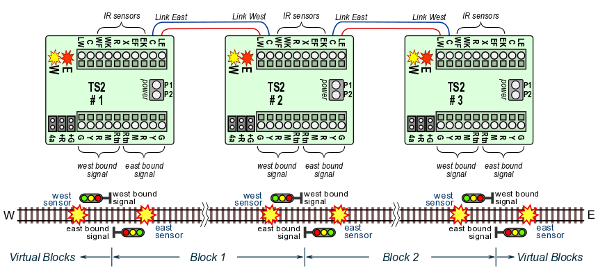
Problem is these use IR, not insulated rail.  But like the Atlas controls, would it be hard to have two inputs to the circuit board.  One will engage the red light (Current block.) and the next would engage the yellow light (Following block.)?  If neither has an input, then the light would be green.  So you would need two sets of boards, one for each direction, which is how Atlas handled it.  And if the boards are low cost kits, I would not mind having two sets, one for each direction of travel.  With that said, you could make it a simple trigger and it's up to us if we attach it to the current block's red light, or the previous block's yellow light.  That would give two boards in each direction, so 4 for one block.  But as pointed out here, the low cost signals use a common, so two lights can't be powered at once. 

How I'd like the board to be is have two inputs (Via isolated rails.), 3 outputs (Red, yellow, green), and power input.  Input 1 is the current block, and Input 2 comes from the following block.  When the board is powered on, it shows green.  When a train entered the block, triggering Input 1, the light goes red.  When the train enters the following block the board is triggered on Input 1 and 2, but still shows red due to Input 1 still triggered.  Once Input 1 is no longer triggered the light goes to yellow as it is still triggered on Input 2.  Once no longer being triggered on Input 2 the light goes back to green.  Perhaps instead of calling it Input 2, it could be Input from following signal.  Then you can have another output on the board, Output to preceding signal, which really is just a pass through for Input 1.

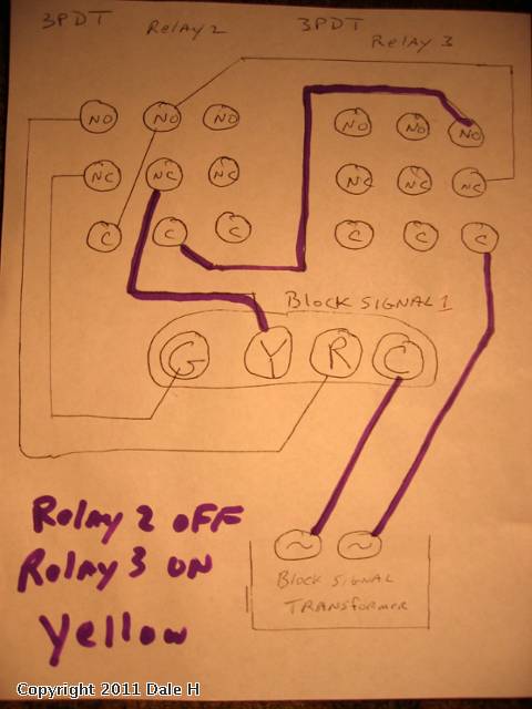
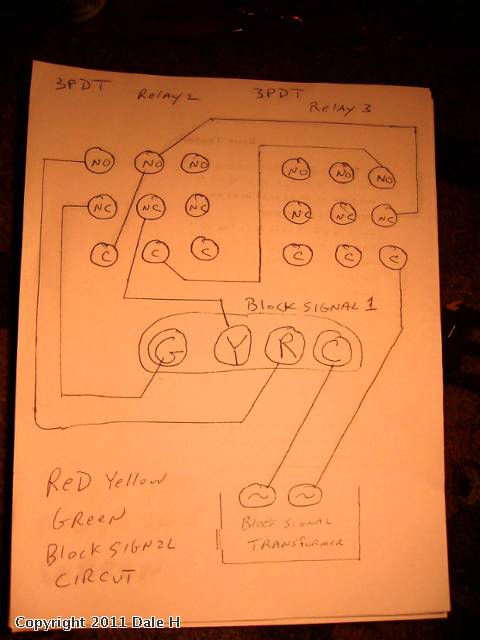
So the logic of the board is I is the Inputs, and on is triggered and off is not triggered:

I1 off, I2 off then show green.

I1 on, I2 off then show red.

I1 on, I2 on then show red.

I1 off, I2 on then show yellow.

But like John says, it's not as easy as someone else doing it, and I'm a mechanical engineer not an electrical engineer.

MJCAT posted:
So for about $9 ($3 for the nano, $1.50 for the breakout board, $4.50 for 3 logical level mosfets )  you can add a really prototypical crossing operation to existing crossing signals/gates on your layout, and each $9 investment would allow you to control 3 different crossings.

Hmm, can you explain the three different crossings for $9 for all three?  Don't you need more sensing at least?

gunrunnerjohn posted:
MJCAT posted:
So for about $9 ($3 for the nano, $1.50 for the breakout board, $4.50 for 3 logical level mosfets )  you can add a really prototypical crossing operation to existing crossing signals/gates on your layout, and each $9 investment would allow you to control 3 different crossings.

Hmm, can you explain the three different crossings for $9 for all three?  Don't you need more sensing at least?

Ok, you can do TWO crossings per nano.  As I was writing up the below, I caught the fact that I had gotten my arduino boards mixed up on the number of analog pins they have.  The nano has 8 analog pins.  We need 3 per crossing. 

For the insulate rail detection, I use 2 input pins per detection block on the nano; a digitial pin and an analog pin.  

The digital pin is configured as Input_Pullup, which causes the arduino to attach the pin to +5v through a 50K resistor internally. We attach the detection rail to this pin, and also to the analog pin. The digital pin is doing nothing other than allowing us to connect to +5v through a pullup resistor internally, so we dont need to add these components externally.  We can then perform an ADC read on the analog pin.  When nothing is on the detection rail, thebanalog pin would have see the full +5v, and would report back a value of nearly 1023.  If something brings the detection rail down to ground, the digital pin voltage would drop to near zero, and the ADC value would drop. Placing your fingers across the ground and detection rail drops the voltage enough to be detected.  (Digital value drops to just below 1000. )


Bob posted:
Adriatic posted:

  Could someone explain why and how crossbuck lights & bars (not track signals) could benefit from a directional detection. I can only seem to focus on the fact that if the space between A&B is occupied, both crossbuck signals should activate. Speed doesn't even really matter; on slow days you wait longer to cross. That is what I've observed on the real rails. I even knew the exact A&B spots for crossings near me; fast or slow they triggered the crossbucks at the same spot every day.

The crossbuck signals should activate while the approaching train is some distance from them, but they should stop as soon as the train has cleared the crossing.  The fact that the distances from the crossing for activation vs. stopping are different means that directional detection is needed for this feature.

Thank you, you filled the gap. I hadn't thought of about a good shut off at a slow creep.

But still not really a directional need. A seperate occupancy detection is needed (2 if super fussy), for triggering the same circuit to off.  But I also see that with track signals, the directional aspect is a near must and tieing the gates into that is a no brainer. 

gunrunnerjohn posted:

Do you have any protection for the uP input pins?  Nasty things can happen on the rails, I'd want some protection for low voltage inputs.

Correct. Cause if you allow any nastiness above the 5v to hit one of those pins, the little tiny nano  turns into a highly effective space heater. You wouldnt want to be holding it in your hand when that happens.  Trust me. 


Jumping ahead from the "what" to the "how", I'm curious if you've thought about the ability to re-program (aka add features) to whatever you come up with.  Specifically I think "We" have become accustomed to the idea that our software "apps" in our smartphones, tablets, PC's, etc. are constantly being updated/refreshed with the latest and greatest.

So the hardware becomes the bricks-and-mortar...and the software can be fluid.  That said, there are many options but the two that stand out for a LOW-COST solution:

1. A $2-3 Arduino with a USB loader.  AFAIK, this requires the end-user to download "unique" software.  If functionality is changed you need more than drag-and-drop on your PC/laptop.  I highly doubt the typical OGR end-user will be writing code.  Hence feature upgrades would be done by the handful of guys here on OGR that know how to do it, and the executable would be made public.

2. A microcontroller (it could be an Arduino) that reads a $2 microSD card that contains the software.  So if you upgrade the app, you simply post the new software on OGR and leave it to the end-user to drag-and-drop the new software into the microSD card and then plug that card into the signaling board.  Most people have smartphones and "get" the concept of the microSD/SIM card and should be able to move a file from a PC or whatever to a microSD card without loading custom Arduino "loader" software. 

This is a brave new world.  Again, I realize I'm jumping ahead but I believe this can fall in line with not-to-exceed $10 (or whatever) cost target.

Stan, you bring up a good point.  Given the cost target, I was thinking of the Arduino Nano, but I don't know if there is a variant that has a microSD capability native.  What would be cool is a canned way of just jacking the Arduino Nano into a USB port and running a program that did the load automatically. 

OTOH, I suspect many folks would be able to at least install the Arduino app and upload a provided file, that may be the lowest cost solution.  Adding a microSD seems to run up the cost, and then there's all the programming to actually seamlessly load the program from the microSD.

My vision at this point is to concentrate on the interface capability as the "smarts" would all be in the Arduino.  If we have the ability to accept various inputs and have sufficient flexible outputs, we can do a lot of different things with the same platform.

Looking ahead a bit, I envision a bunch of Arduino based controllers placed all over the layout. A full fledged ABS or CTC signaling system could amount to a microprocessor at each block. Add to that controllers for grade crossings and servo controlled switch machines and there could be more than you would want to disassemble for new software upgrades.

What is needed is a way to communicate between the various microprocessors. The good news is that there is hardware that makes this fairly simple; RS485 multi-drop connections. The bad news is that, while I've tried to work out something on this, I have not had much success.

Still, if the Signal Controllers were connected as addressable units, the chaining of signals for block control could be achieved with messages sent one to another. Software upgrades could also be done using the same communication link so that all units of a certain type could be downloaded at the same time and without being extracted from under the benchwork. RS485 is two wires, usually in twisted pairs.

One of the major downsides of a RS485 Type Connection, is it can be slow, since it is a serial type link. I have seen it used in some products I work with, and a 2 MB file can take 30 minutes to send to the target device. That may only because what we use it for is sending images to elevator displays. In what we use it for it has 5 wires. Two for receiving and two for transmitting and a common. Though your mileage may vary.

But we're not pushing 2MB files over a signal network. I'm running my whole layout with JMRI and CMRI over a 485 network with a Raspberry PI and four SMINI nodes with no noticeable lag between the user interface screen and layout response. A signal network should be way simpler than that, and network traffic should be very low given signals don't change THAT fast.

I think I need to start a new thread.

The original purpose of this thread was a "simple" and "inexpensive" signal system that would address the needs of a vast majority of the users.  I realize that the capability exists to do amazing things with technology, but that runs up the cost and REALLY runs up the complexity!  Once you get into multiple signals, communications, central signal control, etc., it spirals way out of control in both time and money to build it.

I want to start with a stand-alone signal board.  I contemplate the idea of having extra ports to expand on the basic functionality, but when you start talking about linking the whole layout with RS485, the "simple" train clearly has jumped the tracks!  We have to crawl before we can walk.

Things seem to go from simple to complex really quickly on here from what I have seen. I think because we want to do more and more with the layouts as technology evolves and changes, and gets smaller and smaller. I have a project I am going to be doing for school using a Raspberry Pi to write some code to have some lights in buildings do some thing. So I can sort of see what you want to accomplish with this.


All this is great stuff, and I'm sure would be super cool to have running.  However, I think there's a large audience that just wants some basic signal capability at low cost.  That's what I was trying to address.  If you want to spend more money, there are tons of commercial offerings that already do a lot of this stuff.  I'm seeing a DIY solution that can be assembled for a few bucks and offer basic signal functionality with a handful of "nice to have" options.  If the build cost goes much over $10, the project goes way off track.

A good idea that came out of the discussion is to have the board support going a more complex route, but have the option of assembling a simple signaling system by simply leaving parts off.  As far as programming the Arduino, the same thought applies.  I'm visualizing a simple signaling system being first implemented and then the community has the option of expanding it and using the extra capability that is built into the board.  It's a building block approach, not an all-in-one solution right out of the gate.

LOL.  Well, some 5 years ago, there was this OGR thread discussing how to drive the 3-aspect we_honest signals.  We_honest offered their signal controller board as described earlier.  The thread showed how to roll your own circuit for $1 or so in components with the timed-yellow.  The same circuit could drive the 3-LED RYG or the 7-LED PRR style.

cheap signal controller

GRJ has already shown how to roll-your-own insulated-rail trigger (his so-called ITSD) in various threads.  So the two circuits in combination could provide a low-cost (less than $5 in parts) option.   No daisy-chaining capability, no clever bi-directional operation, no crossing-gate flashing, just basic drive-the-$4 3-aspect signal.  End-of-story!  


Attachments

Images (1)
  • cheap signal controller

Yep Stan, you are so correct.  I was thinking perhaps one step up with a bit more flexibility, but feature creep (or rather feature over-speed) seems to have taken over the project!   I kinda' liked the idea of an inexpensive and expandable platform, getting into control for the whole layout is over the top for this application.

Perhaps I'd be better off just to come up with something and present it.

And, if low-cost is the objective, I've posted OGR threads on how to use low-cost eBay relay modules to perform the timed-yellow delay.  Less than $5 per signal head.  No tedious component-level assembly/soldering if using $1-2 eBay relay modules (as opposed to wiring up a 555 IC timer chip). 

Again, No daisy-chaining capability, no clever bi-directional operation, no crossing-gate flashing, just basic drive-the-$4 3-aspect, 4-wire, common-anode LED signal head. 

For 3-aspect RYG:

For 3-aspect PRR in this case with a 25-cent roll-your-own optical occupancy detector instead of an ITAD.

I will happily use a simple RR signal control board on my currently in planning stage year round Winter Themed Layout that I plan on putting in my Dining Room. 

I wonder if it could be made to control both crossing signals and normal RR signals on one board, or if that would be to much of a draw in one board. Since my winter themed layout is going to be significantly smaller than my layout in the basement.

My thinking is along the lines of using the raw track power to handle incandescent lamps so that the power supply on the board wouldn't have to supply that power.  LED's are not a big deal, and those would probably be OK.  The tricky part is how it's being triggered and what logic makes sense to have both road crossing and track signalling active from the same sensors.

How about just going with the items in your first post that started the thread? I think that is a pretty good list of features to start with and something I would certainly be happy with. As things progressed the idea of possibly of adding more capability to the original board could be entertained and the board could be expanded if things develop? Since I am no circuit designer, some of the original items you suggested may even prove to be difficult or too much for the initial board design? Some of us (me for sure) can really come up with the features, but also have no idea what is involved in creating a circuit to make it happen. Reference to your signature line once again comes to mind...  But I really do get that part of it! 

One other thing, these boards could be used as a starting point for us 'prototypically challenged' folks that are not really sure how all these signals work together anyway? They would not have to 'do everything for everyone'. We could upgrade to the already available stuff for more advanced signaling, etc. as we go along. Maybe sort of a starting and learning point or starting to learn so to speak? Some would probably end up being good with what they had and others may want to go to more advanced methods? 

Last edited by rtr12
stan2004 posted:

LOL.  Well, some 5 years ago, there was this OGR thread discussing how to drive the 3-aspect we_honest signals.  We_honest offered their signal controller board as described earlier.  The thread showed how to roll your own circuit for $1 or so in components with the timed-yellow.  The same circuit could drive the 3-LED RYG or the 7-LED PRR style.

cheap signal controller

GRJ has already shown how to roll-your-own insulated-rail trigger (his so-called ITSD) in various threads.  So the two circuits in combination could provide a low-cost (less than $5 in parts) option.   No daisy-chaining capability, no clever bi-directional operation, no crossing-gate flashing, just basic drive-the-$4 3-aspect signal.  End-of-story!  


Stan and John, Your circuit together with a variation of GRJ's "Itad" work great. Can be modified to to suit 2 or 3 light colored or directional signal if you like. Also it could probably  modified to use multi colored LED"S. Less than $3.00 using GRJ's insulated rail "Itad".

As Stan has shown, it's pretty easy to cobble together a basic signal driver.  If you were to create one PCB for the signal driver and the ITAD components, you could probably get the total price for parts to the $5 ballpark, and maybe even a little less for a single signal solution.  Of course, you would want some nice terminals to connect to the track and signals, that tends to run up the cost.

Hoping maybe Stan2004 or GRJ could help with this question....  Quite a while back Dale H posted a signal control scheme for 3 light signals using 3PDT relays....   I found the original sketch of the wiring diagram  it's shown below.....  I would like to adapt this to some LED signals that I have purchased that are 3 volt common anode with dropping resistors installed (NJI)...  so I can power them with 9 to 12 VDC...

So I have 2 questions.... Where Dale H drew in "Block Signal Transformer" power (AC symbol),  (Lower Right Hand corner)...    I am using insulated rail which is sending AC common to close the relay solenoid ?    I am using a separate PW Lionel DC transformer which has the negative DC  terminal tied to my AC Common on the layout which is how I am driving all my other 12 VDC DPDT relays...   That's working for DPDT so it should work on my 3PDT  12 VDC relays ?

Next question the power going to relay 3 in Dale's sketch  should be the 10 VDC as I am using LED signals not incandescent lamps ?  Also,  I assume that if I hook of 6 of these in sequence,  I should follow his diagram, then all lower right relay common or collector terminals, (not sure which term is right) get the 10 VDC + to the 3rd set of relay contacts on the RH side for every relay ? 

Other than that, I just keep copying the interconnection scheme he drew up between Relay Block 2 and Relay Block 3

Last edited by chris a

Perhaps it's on OGR somewhere but you can find Dale's post on the O-gauge archive site here:

http://www.jcstudiosinc.com/BlogShowThread?id=577

As you say, the diagram shows the AC "Block Signal Transformer" driving incandescent bulbs.  If you have a common-anode LED signal-head with built-in resistor(s) to handle 9-12V DC:

blocksignalschematic

Note that while the diagram shows 3PDT relays, you only need a DPDT type for Relay 2 and a SPDT type for Relay 3.  Of course, if you already have the 3PDT type in-hand they will work too.  

If you peruse the Electrical Section of the O-gauge archive site referenced above, Dale posted several additional ideas where the 3PDT type relay can be put to full use for more complex block signal applications.

For example, I'm not sure if I understand your 2nd question, but if you have multiple LED signal heads on consecutive adjoining blocks, then you can use the "unused" DPDT contacts of 3PDT Relay3 to become the "used" DPDT contacts of Relay2 for the next signal head.  So only one additional 3PDT relay is needed for each additional signal head.  OTOH a lot of guys use the unused relay poles to cut power to a controlled block (if Red), reduce voltage (if Yellow), apply full power (if Green).  I guess it all comes down to exactly what you're trying to do!  


Attachments

Images (1)
  • blocksignalschematic
Last edited by stan2004

Stan2004:   Thanks very much for the reply.    Yes, it was hard to describe my last question,  but essentially I was trying ask whether the relay & wiring pattern repeats, if I want to hook up sequential adjoining blocks all with multiple light LED signals......

As you put it:  "multiple LED signal heads on consecutive adjoining blocks, then you can use the "unused" DPDT contacts of 3PDT Relay3 to become the "used" DPDT contacts of Relay2 for the next signal head. "  I think this sentence gets to the heart of what I am asking, but now I am a "little confused"....     Let me go do some searching the jcstudiosinc for Dale's other posts about 3PDT....   

I was thinking for each block ,  I would need to install one (1) -  3PDT relay, and one LED signal with 3 or more LED lights (see below, for why I say "3 or more LED lights"

I am not looking to control track power in blocks,  I am  interested in using spare relay contacts if any are available to control other lights on the signals....   I purchased some NJI,  B & O style,  CPL all of which have more 3 lights,  some have the "lunar blue" completing the circle on the round face, others have from 1 to 3 markers on crossbars above and/or below the main CPL target....  

So, as I am doing research on what different signal aspects were communicated by the additional lights,  I would like to come up with at least a believable resemblance control scheme for controlling the additional lamps....

In some locations this won't be any more challenging than having the Markers on all the time, or tied in parallel to one of the 3 colors R, Y , G...

By early next week, I'll have the signals and relays with 11 pin bases in hand, so I was thinking about setting up a test board with 4 blocks or 14.5 inch track each, 4 relays and for signals and doing some bench testing to see what works...


B and O CPL jan3

Attachments

Images (1)
  • B and O CPL  jan3

Perhaps you've got it all figured out or found a similar diagram, but if using the 3PDT contacts strictly for driving the LED signal heads:

3pdt block signaling

For N signal heads on consecutive/adjoining blocks, you need N+1 relays.  The leftmost relay can be a DPDT type.  The rightmost relay can be a SPDT type.  All relays in between are the 3PDT type.  Or, use all 3PDT types and no need to make some connections on the leftmost and rightmost relays.  Example above has 3 signal heads requiring 4 relays.  I drew the wiring to each signal head separately to illustrate how the wiring "pattern" to each signal head simply repeats.  If drawn all together it would look like a mess! 

If you're messing around on the bench, you might look into placing a 25 cent resistor-capacitor filter on the DC relay coil contacts to demote chatter.  That is, when a consist enters/exits a block, the lightweight wheel axles (e.g., pilot truck on a steam engine or trailing truck on a caboose) may make intermittent insulated-rail contact causing the LED signals to flicker.  I'm pretty sure Dale covers this ... or I can elaborate if this is of interest.

Attachments

Images (1)
  • 3pdt block signaling

Stan, your drawings are always very good and explain things very well, as do your written descriptions. Thank you again for all the help you give us around here! 

Adriatic, here is a post from Dale H from Dec 2016 saying he was recovering from a stroke. I emailed him shortly after reading that to wish him well and a speedy recovery. I've never heard back from him so I don't know what has happened to him? Sure hope he is still with us and doing well. I always enjoyed his 'relay logic' posts, he had some neat stuff that he had done with relays like automating his entire, large, conventional operation layout with them. His layout is really neat too as is the building he had it in and everything else he had in there.


Stan:   I definitely didn't "have it all figured out", but your drawing and accompanying detailed description is amazing !!...  What a really cool way to present it.   I started doing a drawing with 4 relays and it got confusing, and messy, really fast trying to get all the wires hooked up to the relay in front and behind.....  I don't think I would have figured out the N + 1 requirement...    

I did find a bunch of Dale's drawings that were on jcstudiosinc., detailing the SPDT, DPDT and the 3PDT configuration,  but I was struggling trying to extrapolate what a multiple consecutive block arrangement would look like.    You totally solved that problem with the above drawing and expanation !! 

I have been using the capacitors on the coil contacts,  basically my DC + is set at 10 Volts at the PW lionel DC transformer, then the capacitor brings it up to 12 VDC +/-....   I am not familiar with adding a "resistor" to this filter.   I wouldn't mind hearing the how & why so I can add this to the mix.   I have an ample supply of resistor's capacitors etc.   

Thanks very much STAN,  honestly now I can spend my time building the central relay board, and figuring out when I'll illuminate some of the other lights on the NJI B & O CPL signals...   

With the drawing you provided I definitely don't need to build a test bench set up..    Again, I really appreciate your HELP !!  

GRJ,  sorry for getting way off topic on your thread   -   RR Track Signal Control Board..

chris a posted:

...

I have been using the capacitors on the coil contacts,  basically my DC + is set at 10 Volts at the PW lionel DC transformer, then the capacitor brings it up to 12 VDC +/-....   I am not familiar with adding a "resistor" to this filter.   I wouldn't mind hearing the how & why so I can add this to the mix.   I have an ample supply of resistor's capacitors etc.   

The resistor limits the current surge into the capacitor at the coil when a wheel axle initially straddles the outer-rails.  That is, an uncharged capacitor behaves like a short-circuit when a voltage is suddenly applied to it.  This surge can cause arcing and, over time, pitting of the rail.  Depends on many factors like the power supply, the capacitor size, etc. and you may never see it.  But why not pony up a 1-cent resistor.  Something like 22 Ohms 1/4 Watt.   Go below 10 Ohms or so and you lose the effect, go above 47 Ohms or so and you might starve the coil of voltage.

I don't know your coil current but to achieve any useful chatter suppression the capacitor value will need to be in the 100's of uF.  So this will be a polarized electrolytic type rated at, say, 25V or more.

rc


chris a posted:

...

GRJ,  sorry for getting way off topic on your thread   -   RR Track Signal Control Board..

Well, GRJ's board will need to handle this application though presumably without relays.  A method to "daisy-chain" block signals is a must-have feature.  Additionally, I'd think an LED flicker suppression method (like the capacitor across the coil) is another must-have feature.  So I think we have his attention!  

As for those additional LEDs.  Assuming they are also common-anode with built-in resistors, then it seems you'd just hook up a 2nd, 3rd, etc. LED in parallel to turn on at the same time as any of the primary RYG LEDs.   Of course this limits you to the 3 existing states and there's nothing new...not very interesting.

I am ignorant as to prototypical signal behavior for your additional LEDs, but let's imagine a new "state" where you want an LED to indicate that a signal two blocks ahead is either Yellow or Red.  This logical "OR" can be implemented with 2 penny diodes.  The logical "AND" function is a bit more complicated to implement.  It's these more complex signal behaviors where I think GRJ's control board will make its mark.


Attachments

Images (1)
  • rc

51AECDA1-A0B3-4ADB-B1D0-4287D5BF17C562081687-5AB4-4B0F-A2B9-594408AC7ADAB56AAD92-4B0D-4F03-8361-DFB5791D9AF50EB421DA-27F5-4525-917E-4053860CB3098BFE9EA5-B9C7-4DB0-9782-8CACC4F058174118ED95-9B41-4A1F-AB87-B51E2044D0AAThe system I now use is a very simple one by NJ international there system is about 60$ a block it’s complete with everything you need for single direction or bi-directional and you can daisy chain them to work together I now have 30 of them on the layout the pictures are of me testing out the new system I was impressed on how easy it was to install I tried digitraxx first then went with several other ones but found them to be very complicated and expensive

Attachments

Images (6)
  • 51AECDA1-A0B3-4ADB-B1D0-4287D5BF17C5
  • 62081687-5AB4-4B0F-A2B9-594408AC7ADA
  • B56AAD92-4B0D-4F03-8361-DFB5791D9AF5
  • 0EB421DA-27F5-4525-917E-4053860CB309
  • 8BFE9EA5-B9C7-4DB0-9782-8CACC4F05817
  • 4118ED95-9B41-4A1F-AB87-B51E2044D0AA
Last edited by fl9turbo2

I was thinking of a simple input and output logic signal to daisy chain the boards.  Since I've pretty much decided that in order to be flexible that it would have to be uP based, that should be pretty easy to provide for.

My current thinking (when I get time to think about this), is the Arduino Nano piggybacked on a board with the power supply and driver components.  Using the Arduino allows easy portability of the firmware that is developed and modified along the way.  Also, the Arduino has lots of I/O ports to allow flexibility in what signals it drives.  I'm also thinking at least the provision for one 10A relay so that it could be programmed to control track power if desired based on the signalling input.

20190413_154447

well today i was building on my simple 4x8 layout that i have the plan to sell at some point i figured i would add some signals to the layout to make it have alittle more action using 3 signals on the simple loop and 3 ts2's from azatrax. well they were up and running fine with the exception of i couldn't get the boards to talk to each other and signal accordingly but they did do the count down to color changes . I have track power going to a power block and had 3 of the hook ups for the 3 ts2's and the 4th and so on are going to be lights for buildings. I went to hook up my first light in a building and the 3 ts2's smoked. and turned off. SMH still don't know what happened. 


Attachments

Images (1)
  • 20190413_154447
Last edited by Jhainer

I started a similar discussion on the electronics I wanted to build for a layout I am designing.  This is the thread https://ogrforum.ogaugerr.com/...ontrol-lcc-and-esp32 .   The thread did not generate much interest but I still think it is the best and most inexpensive way to automate a layout.  I have designed and received the boards made by PCBway for 4 of the nodes.  Layout Command Control, LCC, is a NMRA standard.  Several HO LCC enthusiasts are porting the LCC software to the ESP32.  They claim they have 90% say the performance needed on the  ESP32 and are working on improving the software efficiency.  I am building a simple layout to demonstrate LCC, the boards and software.


John, I really do think you could do it all with 3-aspect signaling.  Flashing aspects are cool, as are double aspects, but they add complexity that has to be balanced against play value.  And, if you mean to install bidirectional signaling (which does have play value) 3 aspects can do it quite well.  Signals that simply change color are visually attractive, but they are only decorative, and not useful.  The upside is that they're simple (often actuated by infrared light) but the downside is that a train could stop right after passing the signal and be sitting just beyond it when the signal timer changes the aspect from red to yellow to green.  So, a train could pass a green signal and immediately run into the rear end of the preceding train.  That doesn't bother some, but others want the signal to indicate that the train may safely proceed past it.  You don't need an extra signal at the leaving end of a siding.  In prototype ABS there is usually not one.  The train leaving the siding checks the signal for the main track, then throws the switch and leaves the siding governed by the aspect that was observed.

  1. Green is a no-brainer.  Track is unoccupied in the next block and all switches within that block are properly aligned for the main route.
  2. Yellow indicates that the next signal in advance will be red.
  3. Red indicates that the block it governs
    1. is occupied, or
    2. has one or more switches that are not properly aligned for the main route.

Prototype Automatic Block System (ABS) -- especially where semaphores were used -- did this exact thing.  Rules provided that a train could pass a signal displaying Stop (red) without stopping, at Restricted Speed, if the switch was properly aligned for it to enter a siding.

To get play value from a bidirectional signal system which actually indicates track occupancy, you need four blocks at the minimum, and each signal location requires opposing signals.  This can be either two separate signals, or one signal mast with opposing signal heads mounted on it.  Obviously, you have to insulate the track into blocks, and you have to detect switch position, which, for a person of your electronic abilities, should be very simple.  A couple of more insulated joints can create a trap circuit within a block, to activate crossing signals.  Just make every trap circuit long enough to provide some advance warning in each direction.

I did put a gold-plated signal system on my layout, but it was really expensive, and -- because the railroad is not a whole-house basement size -- I actually think that I could have done it with three indications and been perfectly happy.

It's easy to get carried away on signals.  It is wise to remember that they are just another operating accessory and three aspects add plenty of fun to operation of the layout without great complexity and at a reasonable cost.

Last edited by Number 90
stan2004 posted:

Perhaps you've got it all figured out or found a similar diagram, but if using the 3PDT contacts strictly for driving the LED signal heads:

3pdt block signaling

For N signal heads on consecutive/adjoining blocks, you need N+1 relays.  The leftmost relay can be a DPDT type.  The rightmost relay can be a SPDT type.  All relays in between are the 3PDT type.  Or, use all 3PDT types and no need to make some connections on the leftmost and rightmost relays.  Example above has 3 signal heads requiring 4 relays.  I drew the wiring to each signal head separately to illustrate how the wiring "pattern" to each signal head simply repeats.  If drawn all together it would look like a mess! 

If you're messing around on the bench, you might look into placing a 25 cent resistor-capacitor filter on the DC relay coil contacts to demote chatter.  That is, when a consist enters/exits a block, the lightweight wheel axles (e.g., pilot truck on a steam engine or trailing truck on a caboose) may make intermittent insulated-rail contact causing the LED signals to flicker.  I'm pretty sure Dale covers this ... or I can elaborate if this is of interest.

Stan2004:   So I am well into building a central relay panel with 24 of these 3PDT relays.   It took a long time to finish and connect the 240 foot main line.... that happened this past November 2019.   

I decided to use this signal control scheme for the entire main, so I have created 11 independent blocks, and have installed 24 relays,  12 for eastbound,and 12 for westbound signal control.   As of tonight,  the 12 relays are wired for "eastbound travel",  I will start bench testing this tomorrow 1/22

My question Stan:  I am not sure whether I need 11 relays and 11 signals or 12 relays for the 11 blocks/11 signals.  My blocks are alpha labeled A through K... when the train leaves K it enters A ( continuous loop)....

I know it's been 15 months since you helped me out but if you bump into this thread, maybe you could provide some insight.  

chris a posted:
 

My question Stan:  I am not sure whether I need 11 relays and 11 signals or 12 relays for the 11 blocks/11 signals.  My blocks are alpha labeled A through K... when the train leaves K it enters A ( continuous loop)....

I think I understand your question.  If you have 11 blocks and 11 signals in a continuous loop then you only need 11 relays.  They must all be of the 3PDT ilk.  That is, in the diagram each signal is wired to 2 poles of its "local" relay and 1 pole of the "next" block's relay.  In your example, for block K, the "next" block is block A.

Stan as always THANK YOU for taking the time to respond. 

I will share some photos when I get a little further along.   I kind of figured that the answer was 11, just wanted to confirm.  So far I have bench tested the 1st 4 signals,  in the "eastbound direction" and everything is working perfectly.   

chris a posted:
… So I am well into building a central relay panel with 24 of these 3PDT relays.  

So, for the record, where did you get your 3PDT relays?  The jcstudio O-gauge archive website referred to earlier seems to be out-of-service so I think it would be useful to document the relay-method.  I found these 3PDT relays on eBay for about $2 per relay "bare" terminals or ~$3 per relay including socket with screw-terminals. *** (see below update with additional info from Chris)

Untitled

Separately, I can't recall how much documentation there was on the jcstudio site describing the 3PDT relay method, so I sketched out this simple diagram showing how the 3PDT method "works".  I put a black "slash" mark on each relay contact that carries "DC-" for the different trigger conditions indicated by the black X on indicating consist axle(s) straddling the outer-rails of the block.

3pdt block signaling how it works

Separately, there is a contemporaneous OGR thread inquiring about converting an MTH PRR signal bridge to this "look ahead" signaling as opposed to the timed-yellow proxy method.  In the MTH bridge, the stock circuit board that performs the timed-yellow signaling fits in the signal bridge base.  Clearly, the relay method is too bulky if space/size is important.  So this would be another application for a compact circuit board as proposed at the beginning of this thread.

*** Update with more attractive pricing and U.S. shipping from subsequent post:

3pdt relay with base

Attachments

Images (3)
  • 3pdt block signaling how it works
  • Untitled
  • 3pdt relay with base
Last edited by stan2004

I have been designing the electronics and signaling system for my retirement layout.  The block signal electronics has been one of the most challenging parts of the design.  My initial goal was complete software control of each aspect light (LED) with a materials cost of $1 for the control electronics and $1 for the allocation of the block signal for one aspect LED.  I also have a goal or $0.50 for the block detection electronics.  (I can discuss the block detection electronics in another thread.)  All 3 of the cost goals can be met but with a significant amount of manual assembly.  I am on a cruise and when I get home, I can show the detailed cost of each and post pictures of the assembled electronics.  My layout design has 150 turnouts and over 400 block signals.  I initially wanted 4 types of block signals, single 3 aspect, 2 x 3 aspect back to back, 3 over 1 aspect and a dwarf 2 aspect.  I have draft 3D printable designs for the block signals.  The cost of the 3D printed block signals would be less than $1 per LED but with significant manual assembly.  I will probably use the Wehonest block signals ordered directly from China.  The cost will be about $1.25/LED which is close to the goal for assembled block signals.  Two Wehonest block signals can be used back to back and since it is my railroad, I can have a block signal scheme which uses the 3 aspect LEDs to give information about both paths on the turnout.  (Again can discuss in a separate thread).  The signal electronics, block detection, turnout control and accessory control will all be done with Layout Command Control, LCC.  LCC is a NMRA open source protocol for controlling layout accessories.  A LCC node has a microprocessor that has 16-24 I/Os for detection (input) or control (output).  All the LCC nodes are connected through a Control Area Network, CAN, bus.  (The CAN bus is used as the network in cars.)  This is a good place to start learning about LCC http://www.rr-cirkits.com/Clinics/Clinics.html.  An excellent how-to book is Introduction to Layout Command Control: Basic Concepts and Practical Examples of LCC for Model Railroads by Dana Zimmerli.  The PCB boards for my DIY LCC nodes just came back from PCBway.   The microprocessor I am using is the ESP32.  I am building a small layout to test my LCC nodes and my ability to program them.  The LCC node to drive 20 switches or accessories will cost ~ $15 (~$0.75/Output).  The LCC 20 block detection node will cost ~$12 (~$0.60/ block).  The LCC 20 LED driver node will cost about ~$9 (~$0.45/LED aspect).  The software for the LCC 20 LED driver node is still being developed.  The fall back is the RR-Cirkits Signal LCC P.  The Signal LCC P can have 24 outputs and costs $62.86 ($2.62/aspect LED).  The costs are just for the electronics and does not include wires, cables, connectors or overhead electronics.  LCC allows you to build a large flexible and complex signal and accessory control system for a reasonable cost. 

Hi Stan,  

So I have been buying the 3PDT on ebay as well but from a different supplier..... I get them with the base, in 4 packs for $9.50 free shipping, and they are definitely shipping from the US so I have been getting them within about 9 days of order.  The 3PDT Relays are marked OMRON, designed in Japan, made in China.... See link below:  

https://www.ebay.com/itm/US-Sh...p2057872.m2749.l2649

I am posting a few in process photos....  I am getting there but it's obviously a big project,  22 relays.  11 Westbound Signal heads,  11 Eastbound.....

  I am going to employ an old Dell Battery charger to power this whole board it's got 75 watt capacity,   3 Amps at 19.5 VDC.   I figure I will use 3  DC -DC Buck converters  each rated for max 2 Amps.  I am planning to use 1 to power the common anode NJ International signals, and the other 2 buck converters will each power 11 relay coils each... They have a 2 amp max rating and the relay coils draw 75 mA each, so I should be good to go with that set up.   Just figured out how I wanted to solder in a 22 ohm 1/4W resistor into the trigger line (AC common), and add a 470uF capacitor across the coil terminals....  

After I get the westbound bases labeled in sets for the outbound cables,  I will probably print up some better labels for terminal strip, then it will be on to making up the cables.   I picked up some nice Belden 30 conductor cable, 22 AWG, stranded tinned conductors to make up the cables from the relay panel to the signal locations.  

It helped me to label all the eastbound signals odd numbers, and the wesbound even numbers to keep it all straight on the track plan drawing.....  

Here are a few photos:


DSC06863 [2)DSC06883DSC06884DSC06885

Attachments

Images (4)
  • DSC06863 (2)
  • DSC06883
  • DSC06884
  • DSC06885

Somehow related to this subject (I hope), here is information that I found while looking for an autonomous, simple and cheap red/green dwarf signal which would also include a no-contact turnout/switch position detection:

http://www.circuitous.ca/xHall...tPositionDetect.html

Did anyone here made and O-Gauge version of this ?  Something better to share ?

Thanks !

P.S.: Thanks to Ingeniero No1 (Alex) and Adrian! for their contribution this forum regarding the "Hall Effect" topic, which help to guide my researches.

related topics: 

https://ogrforum.ogaugerr.com/...ue-position-detector (Ingeniero No1)

https://ogrforum.ogaugerr.com/...switches-for-signals (Adrian!)


Well, I try to do things that have a potential for a wide audience, but the way this was spiraling out of control with requested features, it appeared that I'd never be able to cover that much ground.  I also got embroiled in my sound board and now I'm trying to get my remote control family of boards documented and released.  Too many projects, too little time.

I may pick this up again when I get to adding signal to my layout, then I'll be considering what I need.

Add Reply

Post

OGR Publishing, Inc., 1310 Eastside Centre Ct, Suite 6, Mountain Home, AR 72653
800-980-OGRR (6477)
www.ogaugerr.com

×
×
×
×
Link copied to your clipboard.
×
×