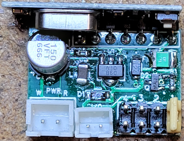
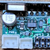
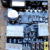
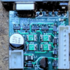
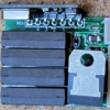
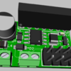
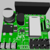
*** Updated with actual board pictures and the final capabilities ***

First up is the composite documentation for each board and a brief overview of the remote control operation.

Universal Wireless Remote Composite Documentation.pdf

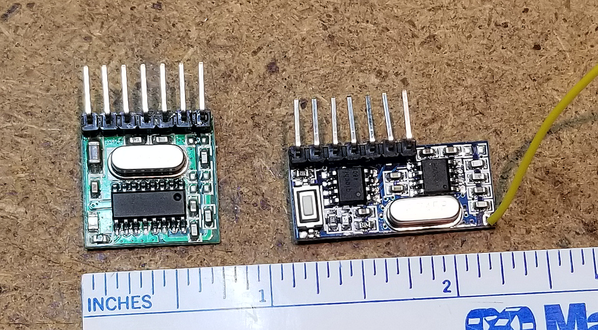
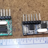
There have been many threads on remote control of accessories and features of rolling stock.  I decided to take a look at some "universal" solutions to the issue.  With that in mind, I have initial designs of a family of boards to perform a wide variety of remote control functions.  All of these boards use the commonly available and inexpensive 1527 learning code 4-channel receivers and transmitters shown below.

433mhzTransmitter & Receiver 1527 Learning Code, 4-Channel

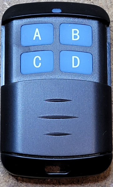
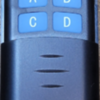
Another transmitter option is also available, the 433mhz 4-button remote control, this will control any of the receiver modules as well.

RF 1527 Keyfob Graphic

The 1527 learning code receivers used have a number of different operating modes.  They can operate in either momentary output, latched toggle mode, or interlocked mode.  When these modes are combined with the operation modes of the four channel transmitter described below, tremendous flexibility in operational control can be achieved.  Each receiver can respond to multiple remotes, and each remote can trigger a different output mode of the receiver.

An obvious issue with the 1527 learning code transmitter/receiver boards is they aren't PnP for model train applications.  They lack the power supply as well as the input and output conditioning circuits for use in our environment.

This is one attempt to remedy that shortcoming.  Don't be too hard on me regarding the exact positioning of the surface mount components.  The object of the exercise was to produce working boards.  No problem making functional boards, but making them look like they were done using automated assembly is outside my abilities.

First Production Sample of 4-Channel Transmitter

First up is a 4 channel transmitter module designed to interface with model train applications.  This board accepts the above illustrated 4-channel transmitter board and provides power and interface logic for the board for a wide range of uses.  Each of the four inputs to the board are optically isolated and will accept any trigger voltage from 1.5 volts to 18 volts AC or DC to trigger a transmit channel.  The on-board power supply accepts AC or DC power from 6 volts to 18 volts to power the internal logic and OEM 4-channel transmit board.  An enhancement over the original design is the ability to program different modes for the first two channels of the transmission.  Four different jumper selectable options are provided, these change the behavior of the first two channels.  In addition, this behavior is microprocessor based so it's possible in the future to enhance/change the behavior if a more desirable option is available.

Jumper options are:

  • Pass-thru: Output active as long as input trigger active.
  • Leading edge momentary: Out active for 100ms on trigger leading edge.
  • Leading/trailing edge momentary: Output active for 100ms on trigger leading edge, again on trigger trailing edge.
  • Two channel interlock: Output active on channel #1 for 100ms on trigger leading edge, output active on channel #2 for 100ms on trigger trailing edge.  Channel #2 input is ignored..

This board can be embedded in rolling stock for internal control of car functions from the locomotive.  It can also be used with the Lionel SC2 or MTH AIU to trigger actions from the respective command system remotes.  A suggested use might be to use the front coupler output on a steam engine to activate a peripheral function.  A magnet on a wheel with a reed switch can trigger a function when you are moving.  You're only limited by your imagination.

RF 1527 4-chan Transmitter Graphic

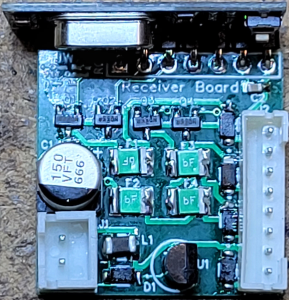
First Production 4-Channel Relay Receiver

Next up, we need a way to receive this command, here's a pair of 4-channel receiver boards.  The first one has four relays to allow total isolation of the switching from the board power.  The relay based board is 1.1" x 1.45" and about .6" tall.  The second board is a FET output based design that allows a more compact 1.1" x 1.0" design and will switch 1/4 amp of power referenced to input power ground.  Both receiver boards use the 4-channel receiver module previously described.

RF 1527 4-chan Relay Receiver Graphic

First Production 4-Channel FET Receiver

RF 1527 4-chan FET Receiver Graphic

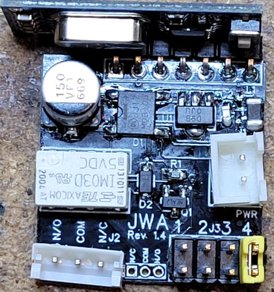
First Production 1-Channel Relay Receiver

What if you don't need 4 channels of control all in one location?  Well, I considered that, and thus a couple more boards were conceived.  These are a single channel relay output board and a single channel FET output board.  The outputs match the previously described four channel boards, just a smaller board with a single channel output.  These also use the same 4-channel receiver previously described.

This relay board switches up to five amps and has two Form-C sets of contacts.  One set is brought out on a 3-pin connector, the second set is available as solder pads on the board.

RF 1527 1-chan Relay Receiver Graphic

First Production 1-Channel FET Receiver

The FET based board allows a single control switched, it can drive 250 milliamps referenced to frame ground.  This small board could be used for tasks like various remote controlled lighting tasks, etc.

RF 1527 1-chan FET Receiver Graphic

With the single channel board, we have a conundrum, the receiver we're using is a 4 channel receiver.  That means we can't program individual buttons on the remote (or channels on the transmitter module) to separate the channels.  So it appears we'll be "wasting" three channels of transmitter and significantly limiting ourselves.

Not so fast!

Taking advantage of a feature of the 1527 learning code family, each of the single channel boards has a Channel jumper field.  The appropriate jumper is added to the board to select which of the four receive channels will activate the output of the board.  This allows you to have four of these boards all programmed for a single 4-channel transmitter.  Each transmitter channel will activate only the board that has it's Channel output jumpers selecting that channel.  Multiple receivers can be programmed to respond to the same transmitter, the net result is we have a single channel board that only consumes one of the channels of our transmitter's four channels.  The relay board is 1 x 1.1 inches in size, and the FET based board is 1x0.7 inches in size.  Overall height is around .6 inches for either board.

The final design strokes have been painted, all the boards have been assembled and tested.

Attachments

Last edited by gunrunnerjohn
Original Post

Replies sorted oldest to newest

Well, the caps and the regulators are rated for 35V, so I suspect that they might do 24V. They're also linear regulators as the current involved is very low, in the 20-30 milliamp range, but the higher the input voltage, the more power dissipation they need.  You're pushing your luck at 24 volts in and 5 volts out.  When I get the prototypes, I'll see what happens with 24 volts and see if the regulators get testy.

However, I'm like Lionel, I like to put a limit on things.  If they're running Lionel stuff, running at 24 volts is playing with fire.

The current rating of the relay is only 1/2 an amp.  Obviously, I can consider different relays, but most of them will also need a driver FET as their coil current exceeds what the receiver outputs.  I'd also have to beef up the power supply a little for the heavier duty relays.  Certainly not rocket science, part of the justification was I wanted to keep it simple for my first cut and I already had a fist full of those reed relays in stock.

If I upgraded the relays, I'd probably pick the PB 5-1462037-9, they have a 20ma coil and 5A DPDT contacts.  However, four of those all activated would be 80ma, probably stretching the capability of the 100ma regulator with the receiver as well.

After giving some thought to some of the comments, and looking again at some of the boards, I made a few changes.  In trying to make them really compact, I actually think I didn't totally accomplish that goal.  For the 1-channel receiver variations, I decided to make some changes.  The receiver boards are not that tall if they're not in a socket, so I plan on simply soldering them in place.  This also allows me to access the programming button a lot easier.  I stuck a SIP package in that position to simulate the receiver as I don't have a 3D model of it.

I also changed the relay on the relay board to a 5A relay and allowed for one Form-C set of contacts to be brought out to the terminal block.  This gives you more flexibility, not to mention much better power handling capability.  A second set of Form-C contacts is provided on solder pads for further flexibility if needed.

The jumper block was expanded to a .1" pitch header which allows use of standard .1" jumper blocks to select the receive channel.

These changes also reduced the footprint of the relay module to 1" x 0.9", the tallest component is the receiver board at 0.5", making it a very compact package.  The FET board is 1" x 0.6" and also 0.5" tall.

With the terminal blocks, there is no board soldering involved, just connect a few wires and add a jumper to select the channel.

433mhz Receiver 1-Channel-FET433mhz Receiver 1-Channel-Relay

Attachments

Images (2)
  • 433mhz Receiver 1-Channel-FET
  • 433mhz Receiver 1-Channel-Relay
Last edited by gunrunnerjohn

Some of this could be used with other applications using 12 to 18 volts.  Those who power things off 13.8 battery power.  Trucks, RV's, emergency power....

Anything with more than about 7 volts DC or 6 volts AC up to 18 volts AC or DC will power them.  Truthfully, they'll probably handle a little more voltage, but I'm trying to keep from over-specifying the max limit.  Since I use a linear regulator, there is a limit to the high voltage where the regulator is dissipating too much power.

After giving some thought to some of the comments, and looking again at some of the boards, I made a few changes. 

A lot of good stuff snipped----

Can you get SMT TVSS units? In the back of my mind I can see these being used to control 022 switches and uncouplers and such, I'd fear for the life of a dainty little relay like that if the contacts go unprotected.

Just my $.02

Last edited by PLCProf

GRJ,

A few years back I took a different approach with one of those remote control sets.  I put the receiver in a boxcar.  Then attached a small wire (small 2 pin JST)to each end of the boxcar, connected to a relay contact.  I made a plug in helicopter car and another "action car" for the other end, with the boxcar in the middle.

The remote allowed me to control two other cars with a simple 2 wire tether to the boxcar in the middle...  Worked great on our modular layout - launched the helicopter while on the run!

(ps. I thought you were getting into the IR stuff! )


Last edited by eddiem


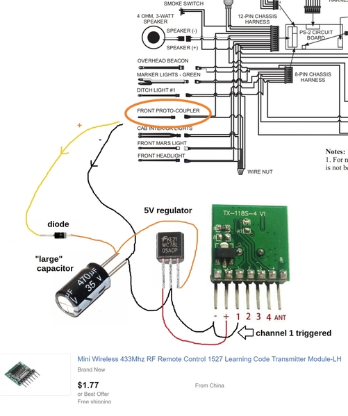
... A suggested use might be to use the front coupler output on a steam engine to activate a peripheral function. 

On the MTH PS boards, the coupler output signal is an extremely short DC pulse (less than 0.1 seconds).  Would such a pulse be long enough to trigger the transmitter to send out a properly coded burst?

For the specific case of using an "unused" MTH PS coupler signal, I'm imagining a non-universal alternative perhaps like:

minimalist transmitter for front coupler

Only 2 wires that go to the electro-coupler are needed.  That is, you do NOT need to provide continuous power to the transmitter module.  The coupler outputs are capable of driving several Amps (DC)...albeit briefly.  So the idea is to charge a capacitor (470uF shown but some math needs to be done) with the huge available coupler current.  Then, since the transmitter module itself only requires a few mA of current, the capacitor would slowly discharge keeping the transmitter active for 1/4 sec, 1/2 sec (or whatever).
In one of your transmitter schematics you show a capacitor across the trigger input.  I haven't done-the-math but given a short trigger pulse into the opto-coupler, would there be enough charging current to that cap from the opto-coupler output?  And is the cap large enough to keep the channel triggered for whatever time is required to send out a "fully-formed" RF burst? 

Attachments

Images (1)
  • minimalist transmitter for front coupler

Stan, if that pulse is so short, I'm wondering if it has enough duration to charge that cap and generate the pulse you speak of.  Have you tried what you illustrate there?  If that works, you have your solution.

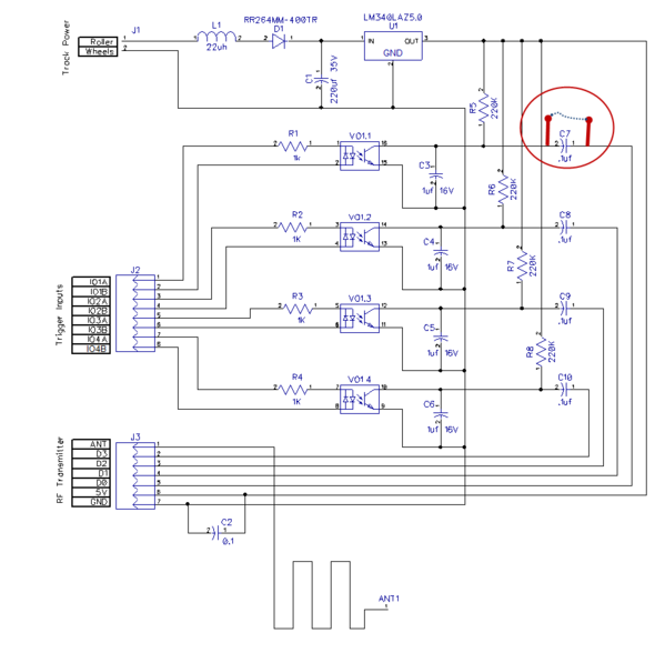
As far as the cap value, that was sized to filter 60hz, the actual time constant with the 220k resistor is 0.22 seconds.  Since I don't know what the internal resistance of the transmitter is, that's kind of a shot in the dark.  However, I will tweak it when I get a prototype if needed.  In the production unit, I'm also considering adding a jumper to short out the series cap to allow for all operating modes, based on the input.  This would be a per-channel basis, see circled mod below.  (Note that I added the cap based on one of your comments. )
__Sample

Attachments

Images (1)
  • __Sample
Last edited by gunrunnerjohn

Stan, if that pulse is so short, I'm wondering if it has enough duration to charge that cap and generate the pulse you speak of.  Have you tried what you illustrate there?  If that works, you have your solution.

Right.  There is some math.  Even if the storage cap internal R and coupler FET have a combined resistance of, say, 5 Ohms, a 470uF cap (RC time constant = 2.4 msec) it would charge to 86% in 2 time-constants (to 95% in 3 time constants, and so on).  So in about 5 millisec the cap would charge up to at least 15V DC even with conventional level track voltages in a MTH-PS circuit.

I measured sample of 1 the 4-channel TX module shown above.  When active it draws 13 mA.  When idle it draws negligible current (in the uA). 

So.  A 470uF cap charged to 15V and drawing 13 mA decays 28 V / sec.  So let's say the 78L05 needs 8V to maintain a 5V output.  The 470uF cap would decay from 15V down to 8V in 1/4 sec...which ought to be enough to release a "fully-formed" RF burst.  In other words, in this albeit contrived example, the circuit behaves as a pulse-stretcher to extend (by a factor of 50) the short coupler trigger pulse of 5 millisec into a 250 millisec RF pulse.

This is all back-of-envelope calculations just to see if even in the ballpark.  And no, I have not tried it as it's not clear if there is anyone actually interested in this specific application.

Separately, I measured the trigger current into the 4 inputs of the TX module.  Curiously, the DC trigger current varied widely by channel ranging from ~25uA on CH1 to ~750uA on CH4.  That is, this is the amount of current flowing out of the trigger pin when grounding it to turn on the transmitter.  This wide range of trigger current (again, this was on a sample of 1) could affect an attempt to use a small capacitor on the input to create a consistent trigger pulse length.


Separately, 


.... This board can be embedded in rolling stock for internal control of car functions from the locomotive. 

 .... A magnet on a wheel with a reed switch can trigger a function when you are moving.  You're only limited by your imagination.

Using the MTH PS coupler pulse to trigger the TX module is essentially an issue of extending the transmit time.  That is, a short trigger is extended in time to transmit a longer RF burst.

There is the separate problem of shortening the transmit time.  If the trigger signal is one that remains active for seconds, minutes, or hours, you still only want to transmit a momentary RF burst of 1/4 sec, 1/2 sec or whatever.  This is a separate problem.  As mentioned in different threads, I can see this problem when using, say, the tail-light output of a PS board to control the tail-light of a trailing car.  So, for example, let's say you want to wirelessly (no wire tether) echo the lead-engine's tail-light to the trailing engine's tail-light.  Since the tail-light is ON for as long as the lead engine is in reverse, if the tail-light voltage directly feeds the TX trigger the transmitter would be active for minutes, hours, whatever.  This is undesirable.

I'm not sure about the applications for the magnet and reed switch example you state, but I can imagine a scenario where the wheel comes to a stop on the reed-switch so the reed-switch is closed for a long period.  Again, you wouldn't want the transmitter continuously on. 

In either case you may also want the transmitter to send a separate burst when the trigger turns off.

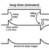
bi-slope triggering

Again, I've not kept up with all the changes in your schematic(s) but generally speaking a series coupling cap will indeed provide a momentary trigger that vanishes in response to the OFF-to-ON transition.  BUT, it generates a "negative-going" pulse when going from the ON-to-OFF transition.  This might not be suitable for triggering the TX module.  As shown in above diagram, it would seem desirable for a so-called bi-slope triggering circuit to generate the same momentary trigger pulse in response to either edge/slope of the incoming trigger signal.

Again, it's not clear how much interest there is in this kind of remote/wireless operation.  This is starting to slice the pie rather narrowly and I do not want to detract from the more general universal flavor of your project!

Attachments

Images (1)
  • bi-slope triggering

You did bring up an interesting issue that I hadn't considered, the really short pulse for some inputs.  I'll have to think a bit more on that and see if I'm covering those.

The widely varying currents to transmit is a bit of a surprise, that's something I didn't really expect.  I think as long as for the maximum current draw I have enough time to send a proper transmission, that shouldn't be a major factor.

For the reed switch scenario, I was actually looking at how that might work.  What it really needs is a circuit that times out when the wheel stops turning and sends a pulse and one that pulses when the wheel starts moving.

In the example below, I hadn't considered wanting to trigger on both edges.  In order to accomplish that, I suspect I'd have to add more parts. 

bi-slope triggering

This is one reason why I build a prototype to tinker with.

Well, the transmitter boards came in and I quickly assembled one for testing.

Put it on the bench... no dice!  Never triggered the transmitter.  Tracked that down to the series caps, even tried 1uf and 10uf and still no triggering.  So, I jumped them out and we got results.  I noticed in my collection of transmitter boards that most of them were TC-118S-4 V2, but the one I happened to be testing with was a V1 version.  Not expecting any issues, I figured I'd pop one of those in and just make sure they worked the same.  NOT A CHANCE!   several of the inputs started strobing back and forth, and the receiver was getting inputs from two channels pulsing continuously!  BUMMER, I though I was close!  I couldn't figure out what was happening with the transmitter module in my board, the wave-forms made no sense.  I just powered the board separately and then scoped the floating input trigger pins.  Eureka!  I see a tiny little pulse at 20 ms intervals on every input!  I'm not sure what it is, but I suspect it's the sampling interval for the transmitter.  What was happening is my filter cap to smooth any AC signal on the inputs was coupling all the inputs together.  For the V1 board, that wasn't a problem, it didn't see it.  However, for the V2 board, those little sampling spikes must have been triggering the other channels, which explained the sawtooth I was seeing when the transmitter module was in the board.

Since I had already removed the series caps for each transmit channel and jumpered across the pads, I removed the jumpers and added some signal diodes where the caps were.  Problem solved, no more cross-talk, and the V2 boards work fine now.

This still leaves one issue that I was going to fix unfixed.  Stan had brought up the possibility of momentary pulsing of the output even when there was a continuous input signal present.  That seemed like a good option, though there are times you'd want to have the output signal present until the input signal is gone.  What to do... what to do...

Presumably the V2 boards are what's presently available so I'd think you need to target that version.  I have the V2 and (also) discovered you can't actively drive the input pins "high" (when idle) so I use a 1N4148 signal diode to pulldown to ground when I want that input triggered.  Those pulses on the input could explain why I was measuring a wide range of input currents to trigger an input.

I have a working prototype of a 2-wire attachment to any MTH PS2 (not PS3) bulb output.  It transmits a momentary burst on CH1 when the light turn on.  The light can stay on for minutes, hours, whatever with no further transmission.  But when the PS2 light turns off, it then sends a momentary burst on CH2 (or CH1 if wired as such).  This can be used with a receiver set to either Toggle mode (CH1 on, CH1 off) or Interlock mode (CH1 on, CH2 off). 

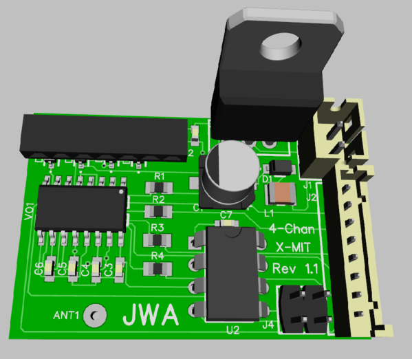
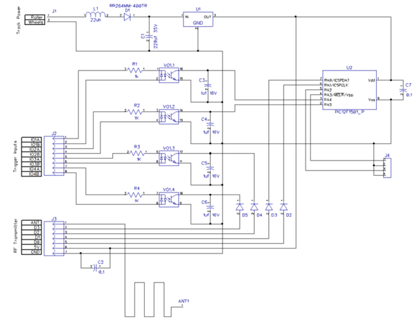
Well, I took another look at the design, armed with the knowledge of what did and didn't work for the V2 transmitter modules.  Here's my new cut.  It got a little bigger as I had to add some parts to solve all the problems and to add in Stan's option of sending a transmission when the input becomes active, and another when it goes inactive.  I also accommodated the other options discussed.  All of this is done with one chip, as you can guess, it's a microprocessor.

There is a 4-pin jumper field, so I have four jumpering possibilities. 

  • 0-0 jumper: Straight through, transmission for as long as the input is active.  This is the default state without any signal conditioning.
  • 0-1 Jumper: One short transmission as the input becomes active.
  • 1-0 jumper: One short transmission as the input becomes active, and again when it goes inactive.
  • 1-1 Jumper: One short transmission on channel 1 as the input becomes active, one short transmission on channel 2 as the input goes inactive.

Note that I only added these capabilities affecting the first two channels, the remaining channels will be straight through from the inputs.

I plan on being able to fold the larger regulator across the top of the capacitor to reduce the overall height of the module.  The transmitter is already laying flat over the components on the left side.

Finally, for Stan, I tested a PS/3 coupler output to the version 1.0 board.  The combination of the opto-coupler and the 1uf cap was sufficient to generate a pulse that the transmitter was able to reliably send to the receiver.  However, a couple of observations.

If there was a coupler across the output, there wasn't enough amplitude to trigger the opto.  Since the coupler only measures a couple of ohms, that makes sense.  If I leave the leads open, then I'm triggered all the time, apparently there is enough switching noise on the coupler outputs to trigger the opto.  I noticed a lot of "hash" on that line when I looked at it on the 'scope.  With no coupler and a 1/4W 100 ohm resistor to knock down the noise, all was peachy keen, and it worked like a champ.  So, it is possible to trigger these with the coupler outputs.  TMCC couplers put out full wave track power for at least 1/4 second, so they should be no problem either.

433mhz Transmitter 4-Channel 1.1 3D

433mhz Transmitter 4-Channel 1.1 Schematic

Attachments

Images (2)
  • 433mhz Transmitter 4-Channel 1.1 3D
  • 433mhz Transmitter 4-Channel 1.1 Schematic
Last edited by gunrunnerjohn

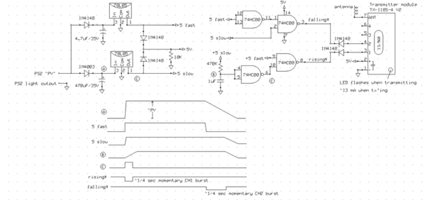
Here's a NON-universal wireless remote transmitter using the TX-118S-4 V2 module.  Specifically, it is meant to work with an MTH PS2 light output.  For example, this could send the direction status from the powered subway car to the trailing car.  Or this could have all the passenger cars turn their lights on/off in sync with the Interior Light of a powered PS2 engine.

To be sure, with your universal module I don't see anyone restricting their options in this way.  But it's been something I've been meaning to get to for years and your project got me off my duff.   There may be some tidbits that apply to your universal version.

bislope ps2 light

As mentioned earlier this only requires a 2-wire connection to the PS2 board/harness.  One wire is PV, the other wire is the PS2 lamp output.  No connection is required to track voltage; stated differently, this circuit is ONLY powered when the PS2 light is turned on.

When the light turns on, the circuit powers up and sends a momentary (~1/4 sec) RF burst as if pushing the "1" button on the remote fob.  The transmitter turns off and stays off even though the light circuit remains on.  When the light turns off, the circuit sends a momentary (~1/4 sec) RF burst as if pushing the "2" button on the remote fob.  The 470uF capacitor which charges up to PV holds just enough energy to power the 5V transmitter for the 2nd burst.

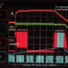
bislope ps2 light scope

Here are some key waveforms taken from a PS2 engine.  This shows the PS2 light turned on then off about 1.2 sec later.  Yes, this is short but allowed me to fit both the on and off transitions on one screen.

The top trace A is the 470uF capacitor voltage.  It charges up rapidly to about 20V DC and is regulated to 5V (2nd trace in Green) DC by a 78L05 regulator.  When the light turns off, the 470uF cap discharges but there's enough energy to keep the 5V and transmitter alive to send the 2nd burst.

The 3rd red trace is the current flowing into the TX module (at 10mA/division).  The 4th light blue trace is a time-expanded version of the current waveform showing the individual RF bursts.  When the transmitter is active it sends repetitive bursts about ~22msec long.  The turn-on and turn-off events send about 10 bursts each.  I'd think you only need maybe 2 or 3 bursts to reliably trigger the receiver.  The ON transmission time is set by the R and C at circled point B in the schematic.  The OFF transmission time is set by the 470uF capacitor and the ~13 mA average current draw of the TX module when active.

The transmitter module is less than $2 shipped on eBay as described in an earlier post.  The other components are generic, widely available and maybe another $1-2. 

Again, I can't imagine anyone building this in light of GRJ's project.  Also, you'll need the receiver side which GRJ has described earlier and would presumably offer them as a pair.


Attachments

Images (2)
  • bislope ps2 light
  • bislope ps2 light scope

Pretty clever Stan.   That does certainly accomplish the task.  You mentioned a similar scheme for the coupler with just one regulator as it's just a pulse.

I briefly looked at discrete components to do the different output scenarios, but it quickly became apparent that it would take a lot of parts to offer the multiple operating modes. In my desire to keep the board small and also reasonably cheap,  I decided that one part with some code would be more cost and space effective.  I socket the 8-pin PIC so I can just program it and then drop it in.  I also thought about adding the additional controls to the other two channels, but that really increases the size of the parts, I need a larger processor with more pins.  I figured a trade-off would be having two channels with the various jumpering options and two that just followed the inputs.

tx option if microcontroller available

Well, if a PIC or the like is on-the-table, you could perform the address modulation in the PIC and send the serial data stream to a basic ASK modulator - 1-pin instead of 4-pins.  This would allow control of an arbitrary number of channels from the transmitter.  As I recall, the bit rate of these modules is in the few-thousand baud range which should be in the realm of possibility even if bit-twiddling a PIC (if it doesn't have a native serial SPI-like port).

Actually this is just a thought exercise as it would be a logistical nightmare to generate the random addresses of the 1527 learning-code protocol - I think there are something like 1 million possibilities.  That is, the TX modules are pre-programmed from the factory with a "random" address and it's the receivers that are taught what address to listen to.  OTOH, I seem to recall Microchip offers some low-cost PICs that have a random number or unique serial number pre-programmed at the factory that the code can read and use for applications like this!

Attachments

Images (1)
  • tx option if microcontroller available
Last edited by stan2004

Well, the PIC is on the table, but only for a fairly basic function.   I want to just use a processor that I already stock for several other projects, and I don't think I want to get into that much research for this particular project.  Learning and programming the entire 1527 protocol and all it's oddities is not in my game plan right now!  The reason I liked these cheap transmit/receive boards that do all the heavy lifting is... well... they do all the heavy lifting!

Pretty clever Stan.   That does certainly accomplish the task.  You mentioned a similar scheme for the coupler with just one regulator as it's just a pulse.

PS2 coupler voltage and current pulse

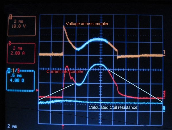
Right.  So first I had to confirm the timing of the PS2 coupler pulse.  Above shows the voltage and current into an operating coupler with command voltage on the track from a Z-4000.  The timing was constant irrespective of track voltage.  At lower track voltages, say below 10V AC, the coupler became sluggish.  As I recalled, the coupler pulse is indeed quite short - less than 10 msec.  And you can see how PV collapses due to the whopping 5 Amp peak coil current to the point that PV starts to follow the 60 Hz track AC ripple.  The lower light blue trace shows the calculated (Voltage/Current) coil resistance in the region of interest.  As expected, the dynamic resistance is in the 2-3 Ohm range.

So the question is/was whether this short ~10 msec pulse (albeit with plenty of current behind it) can provide enough energy to transmit a valid remote-control burst from a 1527-type TX module.  In the bi-slope circuit shown earlier, a 470uF cap charged up to PV voltage had enough stored energy to deliver the turn-off RF burst.

ps2 coupler output powering TX module

Given the huge sag in PV if the physical coupler is connected, I removed the coupler coil and replaced it with a 1000 Ohm placeholder (like your 100 Ohm "placeholder").  Without the onerous 2-3 Ohm load, the short ~10 msec pulse at the 2-wire coupler (1st trace, orange) instantly charges up the 470uF cap to ~20V DC.  We already know this is enough energy to generate a burst.  The coupler pulse disappears and the 470uF discharges (2nd trace, blue) as in previous case.  The 78L05 regulator maintains 5V for about 0.3 sec (3rd trace, green) and then starts to droop below 5V.  The TX module gets out about 10 bursts which reliably triggered the remote receiver.  As shown in a previous post a single 1527-protocol burst appears to be about 22 msec.  So the 470uF cap method appears to perform the time-stretching as intended.  In other words, the ~10 msec coupler pulse is not even as long as a single 1527-protocol burst!

I did find one curious behavior.  From what I can tell you cannot have a TX module input triggered when you apply power.  This appears true even if "isolated" by a 1N4148 diode.  I added a simple R-C (10K x 4.7uF = 47 msec) to delay the pulldown trigger on CH1.  

Obviously with your universal module, power should already be applied to the TX module before you attempt to trigger it so I don't think you'll run across this.

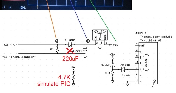
OK.  So here's a thought exercise for your Universal module.  Suppose you externally tie the 2-wire input from track voltage and 2-wire input going to the CH1 trigger opto.  A PIC should draw maybe ~1 mA (vs. ~13mA of TX module) using the internal oscillator at, say, 4 or 8 MHz; as you say it's not doing any heavy lifting so you might even be able to run it at 1 MHz or less to drop the power draw even more.  I'm thinking with just minor code consideration to power-on and power-off transitions you could configure your universal module to operate from a PS2 light output in 2-wire mode - NO connection required to track power!  Likewise, it could operate from a PS2 coupler output in 2-wire mode.  Perhaps the 220uF cap would need to be bumped up a bit though I realize space is precious.  I realize the 1N4148's cost nothing and don't take much room, but you could save 2 diodes by toggling the PIC pin mode between active-low output (when you want to trigger the TX) to tri-state input (when you aren't triggering the TX).

Just saying. 

Attachments

Images (2)
  • PS2 coupler voltage and current pulse
  • ps2 coupler output powering TX module
Last edited by stan2004

Self-Powered is an interesting thought, but that only covers operation in specific circumstances.  Right now I'm trying to make it as "universal" as possible, and having power before I try sensing sure makes the job easier.   I also looked at the coupler pulse, in my case I was looking at a PS/3 board as my test set has a convenient connector for the coupler on the PS/3 test set.   It was very short as you say, I was a bit surprised it actually was able to charge the 1uf cap through the coupler for a long enough pulse to trigger the receiver.

With my setup, the power will come on, and the PIC won't have a low output on the transmitter input until it's done with initialization and I'm processing input signals.  That should take care of the issue of triggering the transmitter before power is applied.

I did have a pleasant experience with the Microchip software.  I've been using the older MPLAB-X 3.65 software from around 2015 for a long time, finally figured it was time to upgrade to the latest, v5.40.  Last time I attempted this with one of the 4.xx versions, it was a nightmare, almost every project had issues with new stuff in the later software!  However, I tried to update one of the features of the 3.65 software and it refused and told me I needed 5.xx software.  So, into the breech I went...  It went like clockwork, every project compiled without errors, and a spot check of the generated code yields identical results.  Amazing when things go right for a change!

For some really tiny processing needs, I spotted the ATINY10 chip while upgrading my MPLAB, it'll be 33 cents in single units!  With four I/O pins and a tiny footprint, it looks like it could be useful.  The programming port will probably be larger than the chip!

... It was very short as you say, I was a bit surprised it actually was able to charge the 1uf cap through the coupler for a long enough pulse to trigger the receiver.


So I went to what appears to be the horse's mouth.

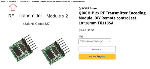
qiachip

The chip on the TX module I have is labeled QIACHIP WL116s.  So under DIY Parts on the qiachip website, it only goes down to the module level.  I was curious if you could buy the chip itself and if there was a datasheet.  So the power-on timing and use of diode-pulldowns remains a mystery of the don't-mess-with-success ilk.

Since a single 1527-protocol burst is about 22 msec...and the PS2 coupler pulse is only ~10 msec, the QIACHIP module must have some kind of logic/timing that releases a complete burst suitable for activating the receiver.  Either that, or as I mentioned earlier, it appears CH1 only requires ~25uA of trigger current.  So even a 1uF capacitor discharging at 25 uA is drooping at "only" 25V/sec.  So if it was charged up to 5V, then that's 200msec to discharge to half its starting voltage.  That's plenty of time to transmit multiple 1527-bursts.

Let's be clear.  I'm all-in with the universal concept.  I'm simply saying it would be a nice touch if with no modification, you can simply tie some external wire and turn this into a 2-wire self-powered version that could connect directly to a PS2 light output or a PS2 coupler output.  As mentioned this may come for free but I suspect there might be a few places in the PIC code where you need to keep the self-powered application in mind.  It's been years now since I messed with the PIC stuff but seems there were some power-on configuration settings that control how fast the code starts "running" when power is first applied.  Likewise, when power droops, it seems there were some low-voltage detection configuration settings that control how fast the code stops "running" when power is lost.

Attachments

Images (1)
  • qiachip
Last edited by stan2004

I think it's probably the cap discharge that is doing the job, I was thinking of increasing the size of those to 4.7uf or maybe 10uf.  When I get the uP version I'll do a bit more testing with the couplers and other inputs.  I figure I'll code up the PIC and have that ready for when OSHPark sends back my boards.

It kinda' stands to reason that the transmitter should be able to stretch the trigger pulse, I may fire up my pulse generator and see if it actually does that.

As for the self-powered version, I can certainly see if connecting power and trigger together actually works.  With the totally isolated trigger inputs, that's not a problem electrically.  Maybe the power across the coupler will knock down the "hash" and solve that problem as well.

And now for something completely different.  Explain to me some real-world scenarios/applications of 4-channel operation.  What's neat about the PIC is you can queue triggers.  So if both CH1 and CH2 are triggered simultaneously, you can queue up the CH2 trigger to present to the TX module after the CH1 trigger is dispatched.  

One question is CH3 and CH4 which are separate and do not go thru the PIC.  As drawn, the PIC has no visibility into what CH3 and/or CH4 are doing.  The TX module can only transmit one command at a time.  Now that I think about it, I have no idea what the TX module does if more than one trigger is active at a time (?).

Anyway, getting back to the "universal" flavor of your motherboard, I'm trying to get straight exactly what applications need (up to) 4 channels of triggers and "who" is responsible for insuring that multiple channels are NOT simultaneously triggered/active. 


The four channels are there because you might want to control stuff in multiple locations from one source.  Remember, I'm making single channel receivers that will react to individual channels.  I can see the locomotive having the four channel board installed, and then using the individual receivers, react to a coupler signal, a headlight signal, markers, and perhaps smoke off/on status.  Also, you don't have to use all four channels, but I can envision plenty of times you'd want to use more than one.

Fun fact, the four channels appear to be totally independent.  That is, I can hold continuous transmission on one channel and manipulate the other channels with 100% recognition. The transmitter board we're using, as well as several different brand keyfobs, all will transmit one or all the channels and they're perfectly recognized by the receiver, and when any one goes active or inactive, it's immediately recognized.  Given that fact, I don't see why I have to insure the other channels are not triggered simultaneously, this seems to be a non-problem.

A different problem does exist, that being multiple transmitters.  If you have two transmitters trying to send at exactly the same time, then the messages do get lost.  That's not something that is easy to control, I don't have a solution for that, but it has nothing to do with the design of my transmitter board.  In point of fact, multiple transmitter boards are a problem.

...

Fun fact, the four channels appear to be totally independent.  That is, I can hold continuous transmission on one channel and manipulate the other channels with 100% recognition.

The specs are scant for the TX module from the qiachip website.  So this may be a roll-of-the-dice if they go to V3 or whatever.  Anyway, for the record let me understand exactly what you're saying:

So if you continuously trigger say CH1, the TX module will transmit continuous packets (~22 msec long, every ~30 msec).  But if CH1 is transmitting and you additionally press, say, CH3 then the packets switch to CH3 packets?  Or are the packets alternating CH1, CH3, CH1, CH3, etc.?  Then you release CH3 and the packets revert to continuous CH1 packets?

When you say "totally independent" I'm a bit confused.  If all 4 channels are triggered simultaneously, what is transmitted?

Apparently, they just mux them all, I can sit there with either the transmitter (with my four buttons to trigger it), or a keyfob and press one, two, three, or all four buttons, and all the receiver lights react properly at all times.

@stan2004 posted:

So if you continuously trigger say CH1, the TX module will transmit continuous packets (~22 msec long, every ~30 msec).  But if CH1 is transmitting and you additionally press, say, CH3 then the packets switch to CH3 packets?  Or are the packets alternating CH1, CH3, CH1, CH3, etc.?  Then you release CH3 and the packets revert to continuous CH1 packets?

Correct, exactly what you'd expect to happen happens.  It's like the four channels are muxed, and they always transmit what they should to manage the channels.

@stan2004 posted:
When you say "totally independent" I'm a bit confused.  If all 4 channels are triggered simultaneously, what is transmitted?

I confess, I can't trigger them truly simultaneously, but I suspect they're managing that internally since as close as I can get with two buttons, I never see anything anomalous in the received data.  My belief is they manage the four channels in the keyfob or transmitter module and trigger the outputs properly.

I wouldn't be at all surprised to see that the transmitted word has a bit for each channel, and they're just setting and resetting one or more of them based in their inputs.  I know that's how I'd design it if I were doing it.  I suspect finding a specification for the 1527 protocol might answer that question.

TX-118S-4 V2 transmission

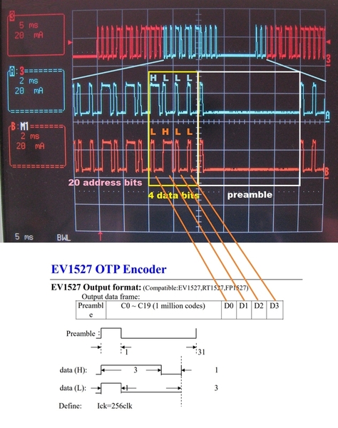
Everything is becoming clear.  As the "datasheet" suggests each burst sends the state of all 4 inputs so any combination of inputs can be simultaneously active.  What's a little confusing at first glance is that successive bursts are back-to-back without skipping a beat so to speak.  That is, the Preamble of the next burst immediately starts after the last data bit of the previous burst.  So what appears like a gap between bursts is really the 31 clock gap of the preamble.

Anyway, for the record, since it appears you'll be using the TX-118S-4 V2 module, the above scope photo shows the timing for a CH1 and a CH2 burst.  The only difference as per the datasheet is the data bits.  As measured, the (1+31) clock preamble + (20 x 4) clock address + (4 x 4) clock data is about 32 millisec for 128 clock periods.   Since each clock cycle is 250 usec and it takes 4 clock cycles to send 1 bit of address or data, that's equivalent to 1000 bits/sec.

I think the value-added of the PIC is to limit the TX module transmission time to a few bursts whenever the 4-bit data field changes.  I realize that as configured the CH3 and CH4 will cause the TX to be on continuously if either are triggered continuously.  This would limit the user to having only 1 of these systems in place on a layout. So the idea would be to only use CH1 and CH2 for any triggers that can stay on for sustained intervals. 

Attachments

Images (1)
  • TX-118S-4 V2 transmission

That's my thinking Stan.  I'm also assuming that some of the outputs would be like couplers that only come on briefly, so they wouldn't be a factor.  Obviously, as I mentioned, having continuous transmission from one of these does knock out any other 433mhz system, not a good thing.

I sat down and coded up the PIC functionality, now I just have to get my boards back in and see how close I am.   I'm still up in the air as to the length of the burst, I programmed in 100ms, but a stroke of the pen can make that any value.

I think having the four operating modes of the two channels will be a nice plus over my first cut, it should fill a lot of the holes.  I was tempted to do all four channels, but that would require a larger part and I'd probably have to surface mount it and program it on the board.  I kinda' like the feature of having the chip in a socket so someone can have a replacement if new functionality is desired.

BTW, nice scope, I am still muddling along with the dual-trace model, I keep looking at the 4-trace ones, but I can't really justify it.

Last edited by gunrunnerjohn

Stan, did you happen to notice that the TX-118S-4 V2 (and V1) have swapped the #1 and #2 outputs from any other transmitter? 

I have three or four keyfob transmitters, all of them are consistent that A = 1, B = 2, etc.  However, these transmitters send output #2 to the first receive channel and output #1 to the second receive channel!  I have to wonder if that's why they're being sold so cheap, someone ordered them and they were screwed up, so they had to fix them and go again.

I'm going to swap those two channels on my transmit board so these boards agree with all the other transmitters.

Stan, the V2 one does the same thing.  I swapped the pins in my code so that it'll match what the keyfob transmitters send.  I always like one to be one, two to be two, etc.   That has to be a screwup with the transmitter module design.  The encoder chip specs clearly indicates it sends them out right, so they must have just wired the board wrong.  Unless that's actually a design screwup and that's the reason they're dumping them cheap, I can't imagine why they'd do that.

PS2 coupler transmission with only 220uF

Of course I'm obsessed with the possibility of a 2-wire self-powered PS2 version.  To that end I reduced the 470uF cap to 220uF as you have in your size-matters module.  I also added a 4.7K resistor across the 5V 78L05 output to simulate the ~1 mA load of a PIC.  Then I triggered it via the 2-wire coupler with both 18V command voltage and then only 12V AC on the track.  As scope photo above shows using short PS2 coupler pulse, 220uF is enough to power ~6 bursts at command voltage!  And even with a lower 12V track voltage it still put out 3 bursts...and reliably activates the receiver.  In other words, I think your 100 msec TX time which would be ~3 bursts is long enough.

So, again, I think by simply parallel'ing your 2 track power inputs and a trigger input pair, there is enough energy in the 220uF to release a valid burst in 2-wire self-powered mode!  I'm undoubtedly the only person who finds this exciting...but I've learned to be thankful for the small things in life! 

Attachments

Images (1)
  • PS2 coupler transmission with only 220uF

Mine has the addition of the opto coupler in the path, not sure how that will affect it.

The results are in, doesn't work.  I suspect whatever load/delay the optos inflict are the culprit.  This is the version without the PIC, so it's not in the picture.  This module just had the trigger go through the opto and on to the transmitter module.  I see the pulse, but it doesn't ever trigger the receiver, I don't even see the LED on the transmitter flash at all.  In an interesting twist, just connecting it that way to the transformer works a time or two, then it insists I power the board first and then trigger the transmitter.

This isn't a train control system, it's for remote controlling stuff like accessories, operating cars, switching lights in passenger cars, etc.  The receivers can be triggered by the transmitter described or with a 4-button keyfob, depending on the application.


The receivers will be placed in various locations, either on the layout for accessories or in rolling stock, and even locomotives, again depending on the application.


Attachments

Images (1)
  • mceclip0
@stan2004 posted:

Of course I'm obsessed with the possibility of a 2-wire self-powered PS2 version.  To that end I reduced the 470uF cap to 220uF as you have in your size-matters module.

What is the actual diagram of what you have working there?  It would seem it would be very simple to make a tiny board plug the transmitter module into.

I was looking at the components to do the transmission without their board, where did you find this little board?  Adding the 8-pin chip and this board is all it would take to transmit the data, a very compact board.  In truth, making the transmitter with our power requirements wrapped around it would be simple if the components and spec sheets were available.

Attachments

Images (1)
  • mceclip0

220uf experiment

The most recent experiment was to replace the 470uF cap with only 220uF as in one of your schematics for the TX side.  Also added was a 4.7K across 5V to simulate the 1 mA draw of a PIC.  Again, this was "only" to see if a 220uF momentarily charged by a brief PS2 coupler pulse can power the TX module for long enough to transmit a valid command.

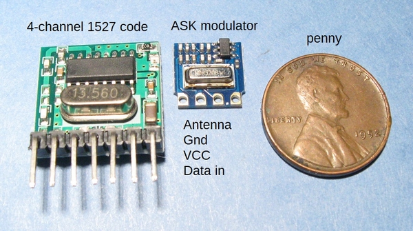
There are many versions of the TX module, try search "433MHz ASK modulator".  For example:

433mhz ask modulator just over a buck each

As discussed earlier the PIC would then be back to heavy-duty-lifting to generate the 1527 protocol.  I don't see this as particularly heavy lifting since the data rate is only about 1000 bits/sec but then again No Job is so easy...well you know the rest!  I think the bigger challenge is how to create (up to) 1 million unique addresses.  As mentioned I recall you might be able to buy PIC chips with factory-programmed "unique" serial numbers that can be re-purposed.  I'm sure there are other methods as well depending on what kind of programmer you have, etc.


Attachments

Images (2)
  • 220uf experiment
  • 433mhz ask modulator just over a buck each

I'm trying to gauge interest in the remote control project, but I'm thinking maybe there isn't as much demand for this as I initially thought.  If this project strikes a responsive chord with you, please speak up.  It may be time for me to put this all back in the box and move on if there is no interest.  No sense in putting in more effort if there's no market for the end result.

I'm trying to gauge interest in the remote control project, but I'm thinking maybe there isn't as much demand for this as I initially thought.  If this project strikes a responsive chord with you, please speak up.  It may be time for me to put this all back in the box and move on if there is no interest.  No sense in putting in more effort if there's no market for the end result.

John,

mentioned above it was only for accessories and such.  Not for a train control, correct?  With DCS control gone, I still think there is room for a high end replacement.

mentioned above it was only for accessories and such.  Not for a train control, correct?  With DCS control gone, I still think there is room for a high end replacement.

I don't think DCS control is going to disappear, and I'm certainly not going to try to invent a new full featured command system for model trains!

@Darrell posted:

I'm interested if I can use this in my postwar barrel car or milk car. I can see it simplifying layout wiring for my sawmill, log loader, and barrel loader as well.

That's pretty much it's intended use, rolling stock and accessories.  For stuff like the milk car and barrel car, the one channel relay model would work great, it switches up to 5 amps.

@NYC 428 posted:

I like the idea.  How would it work, would you need a control board for each piece of rolling stock or one master board and a number of receivers?

It's actually a modular system.  In it's simplest form, you'd just use the little 4-button keyfob to trigger one or more receivers in rolling stock or controlling layout accessories.  If you wanted to trigger the action automatically from either an accessory, track sensor, or a locomotive and/or rolling stock, you'd use the transmitter board and one or more receivers, depending on the specific application.  The individual boards are really building blocks for remote control tasks.

First production configuration receivers, the 4-channel relay output model and the one-channel FET output model.

RF 1527 1-chan Receiver-FET 1.3 Production Config

RF 1527 4-chan Receiver-RELAY 1.3 Production Config

I've decided on the use for my first installation of the 4-channel relay model.

I have a number of the Lionel sound boxcars, wouldn't it be cool to have remote control of not only the sound being on or off, but also the MIN/MAX switch on the car.  Also, given that I have four channels and I've only accounted for two, how about remote volume control?  A couple of low value resistors in series with the speaker (20 ohms is a good starting point), will give you three step volume control.  In this application, I'd simply use the 4-button KeyFob transmitter to control the car.

Attachments

Images (2)
  • RF 1527 1-chan Receiver-FET 1.3 Production Config
  • RF 1527 4-chan Receiver-RELAY 1.3 Production Config
Last edited by gunrunnerjohn

I'm trying to gauge interest in the remote control project, but I'm thinking maybe there isn't as much demand for this as I initially thought.  If this project strikes a responsive chord with you, please speak up.  It may be time for me to put this all back in the box and move on if there is no interest.  No sense in putting in more effort if there's no market for the end result.

John,  My hat is off to you for the time and effort you've put into creating this simple to use control system.  I would definitely be interested in buying a few of the boards depending upon price.  Are you planning to supply the remote with the control boards?  How about instructions for configuring the FOB buttons' to trigger specific relays or would this be pre-programmed?

Not sure if this would be good forum etiquette to ask (if not please email me) do you have selling prices in mind for the 1 and 4 channel boards, remote FOB, and any other necessary components (other than resistors and wiring) for turnkey installation in a sound car or operating car?

Haven't established firm pricing on anything as that's dependent on volume.  So far, I'm not sure there's enough interest to support a production run, hopefully that will change.  Perhaps the spring has slowed down the folks interested in train projects and I'll have to see what transpires in the fall.  I'm also still waiting on the "final" PCB for the transmitter and the one-channel relay receiver so I can show a couple of what production units would look like.

Given the modular construction of the various components, I'm considering that these would be Ala carte products, you'd just buy the pieces you need.  For instance, you may just need a couple of one-channel boards and a transmitter board.  Or, you might want to pair the boards with the keyfob instead of the transmitter, depending on how you want to control the remote units.

As for a practical application of one of the receiver boards and a keyfob, take a look at this topic.  This is something I've been wanting to do for some time, and now I have the stuff to upgrade all my sound boxcars.

Remote Control for Lionel Sound Boxcars

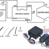
For discussion purposes, here's the eBay example:

ebay remote

The diagram suggests that when activated the receiver applies (via White and Black) 12V DC.  While anything is possible I find it unimaginable that the MTH water tower would take kindly to having 12V DC applied to the 2 wires meant to go to a momentary push-button activation switch.

There are many wireless relay modules that provide "un-assigned" relay contacts rather than pre-wire to 12V DC or whatever.  They typically operate on 5V or 12V DC so you still need a source of DC voltage.  They should also be less expensive than $19.  It's been a while but I think they are $5-10 shipped for a remote plus the receiver with un-assigned relay contacts.  Press button on remote and relay closes for as long as you hold down the button.

Attachments

Images (1)
  • ebay remote
Last edited by stan2004

Add Reply

Post

OGR Publishing, Inc., 1310 Eastside Centre Ct, Suite 6, Mountain Home, AR 72653
800-980-OGRR (6477)
www.ogaugerr.com

×
×
×
×
Link copied to your clipboard.
×
×