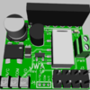
*** Updated with actual board pictures and the final capabilities ***
First up is the composite documentation for each board and a brief overview of the remote control operation.
Universal Wireless Remote Composite Documentation.pdf
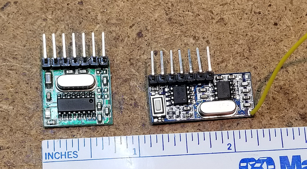
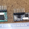
There have been many threads on remote control of accessories and features of rolling stock. I decided to take a look at some "universal" solutions to the issue. With that in mind, I have initial designs of a family of boards to perform a wide variety of remote control functions. All of these boards use the commonly available and inexpensive 1527 learning code 4-channel receivers and transmitters shown below.
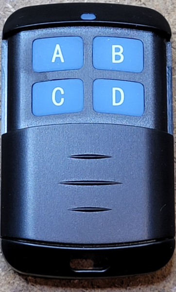
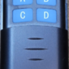
Another transmitter option is also available, the 433mhz 4-button remote control, this will control any of the receiver modules as well.
The 1527 learning code receivers used have a number of different operating modes. They can operate in either momentary output, latched toggle mode, or interlocked mode. When these modes are combined with the operation modes of the four channel transmitter described below, tremendous flexibility in operational control can be achieved. Each receiver can respond to multiple remotes, and each remote can trigger a different output mode of the receiver.
An obvious issue with the 1527 learning code transmitter/receiver boards is they aren't PnP for model train applications. They lack the power supply as well as the input and output conditioning circuits for use in our environment.
This is one attempt to remedy that shortcoming. Don't be too hard on me regarding the exact positioning of the surface mount components. The object of the exercise was to produce working boards. No problem making functional boards, but making them look like they were done using automated assembly is outside my abilities.
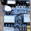
First Production Sample of 4-Channel Transmitter
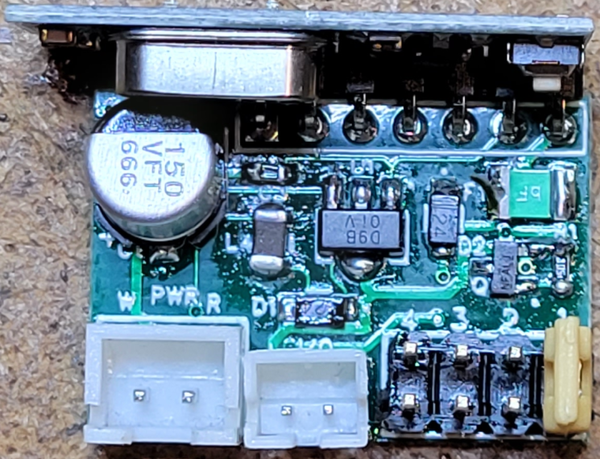
First up is a 4 channel transmitter module designed to interface with model train applications. This board accepts the above illustrated 4-channel transmitter board and provides power and interface logic for the board for a wide range of uses. Each of the four inputs to the board are optically isolated and will accept any trigger voltage from 1.5 volts to 18 volts AC or DC to trigger a transmit channel. The on-board power supply accepts AC or DC power from 6 volts to 18 volts to power the internal logic and OEM 4-channel transmit board. An enhancement over the original design is the ability to program different modes for the first two channels of the transmission. Four different jumper selectable options are provided, these change the behavior of the first two channels. In addition, this behavior is microprocessor based so it's possible in the future to enhance/change the behavior if a more desirable option is available.
Jumper options are:
- Pass-thru: Output active as long as input trigger active.
- Leading edge momentary: Out active for 100ms on trigger leading edge.
- Leading/trailing edge momentary: Output active for 100ms on trigger leading edge, again on trigger trailing edge.
- Two channel interlock: Output active on channel #1 for 100ms on trigger leading edge, output active on channel #2 for 100ms on trigger trailing edge. Channel #2 input is ignored..
This board can be embedded in rolling stock for internal control of car functions from the locomotive. It can also be used with the Lionel SC2 or MTH AIU to trigger actions from the respective command system remotes. A suggested use might be to use the front coupler output on a steam engine to activate a peripheral function. A magnet on a wheel with a reed switch can trigger a function when you are moving. You're only limited by your imagination.
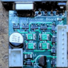
First Production 4-Channel Relay Receiver
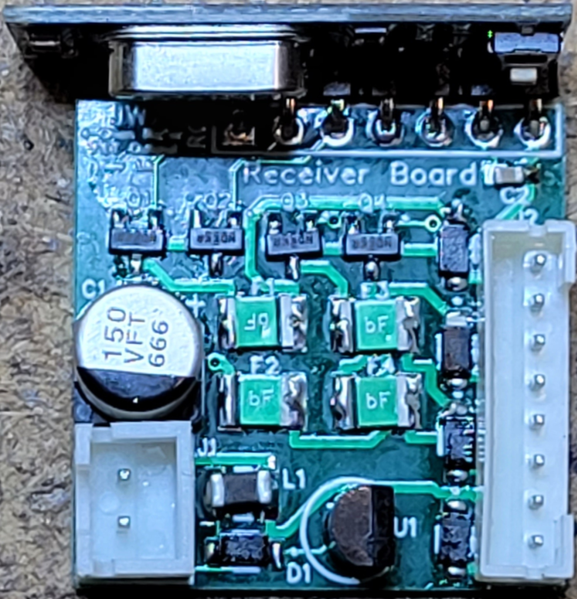
Next up, we need a way to receive this command, here's a pair of 4-channel receiver boards. The first one has four relays to allow total isolation of the switching from the board power. The relay based board is 1.1" x 1.45" and about .6" tall. The second board is a FET output based design that allows a more compact 1.1" x 1.0" design and will switch 1/4 amp of power referenced to input power ground. Both receiver boards use the 4-channel receiver module previously described.
First Production 4-Channel FET Receiver
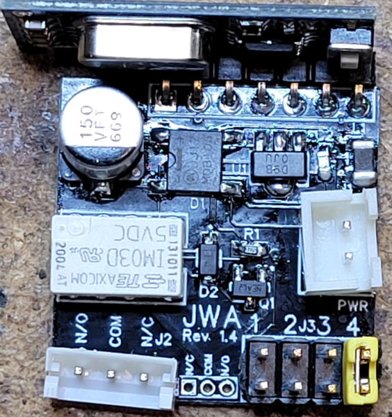
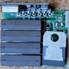
First Production 1-Channel Relay Receiver
What if you don't need 4 channels of control all in one location? Well, I considered that, and thus a couple more boards were conceived. These are a single channel relay output board and a single channel FET output board. The outputs match the previously described four channel boards, just a smaller board with a single channel output. These also use the same 4-channel receiver previously described.
This relay board switches up to five amps and has two Form-C sets of contacts. One set is brought out on a 3-pin connector, the second set is available as solder pads on the board.
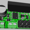
First Production 1-Channel FET Receiver
The FET based board allows a single control switched, it can drive 250 milliamps referenced to frame ground. This small board could be used for tasks like various remote controlled lighting tasks, etc.
With the single channel board, we have a conundrum, the receiver we're using is a 4 channel receiver. That means we can't program individual buttons on the remote (or channels on the transmitter module) to separate the channels. So it appears we'll be "wasting" three channels of transmitter and significantly limiting ourselves.
Not so fast! ![]()
Taking advantage of a feature of the 1527 learning code family, each of the single channel boards has a Channel jumper field. The appropriate jumper is added to the board to select which of the four receive channels will activate the output of the board. This allows you to have four of these boards all programmed for a single 4-channel transmitter. Each transmitter channel will activate only the board that has it's Channel output jumpers selecting that channel. Multiple receivers can be programmed to respond to the same transmitter, the net result is we have a single channel board that only consumes one of the channels of our transmitter's four channels. The relay board is 1 x 1.1 inches in size, and the FET based board is 1x0.7 inches in size. Overall height is around .6 inches for either board.
The final design strokes have been painted, all the boards have been assembled and tested.


