Hi there,

Microwave/RF engineers like myself characterize an antenna in many different ways: pattern, gain, EIRP/TRP, conductive loss and return loss. Of all of these, by far the simplest one to measure is return loss (often called S11 when using S-parameters).

Return loss describes when you send a signal into the antenna port how much is reflected back into the transmitter vs how much is actually radiated. For example if you have a return loss of 0dB it means all the power is reflected and none is radiated. -3dB return loss means half the power is returned and half is radiated, -6dB means a quarter is returned and 75% is radiated and so on.

% Power Out = 100 X (1-10^([S11]/10))

The **formal definition** for an "tuned-radiator" is a return loss of -3dB, meaning the antenna is radiating half of the signal power it is provided.

I had a chance to look at the black stick of wire in the TIU today with a vector network analyzer (VNA) that measures S11 (return loss) by soldering it to an SMA connector and hooking up.

Antenna

I did the measurement both with the antenna up in the air (like when we drill the cover and have it stick out)and lying flat a few mm over a conductive sheet (like it comes inside the TIU when you buy it).


Antenna over a flat conductive surface (about -0.1dB return loss at 920 MHz... meaning only 2.5% of the signal is flowing in and out of the antenna):

Antenna_dn

Antenna up in the air (about -0.15dB return loss at 920 MHz... meaning only 3.5% of the signal is flowing in and out of the antenna):

Antenna_up

Neither of these above measurements meet the criteria of a tuned-radiator (-3dB S11) meaning we wouldn't consider them an effective antenna from a microwave standpoint.


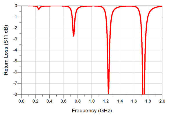
For comparison here's the return loss on this external antenna I bought (better than -8dB S11 at 920 MHz) meaning more than 85% of the signal is flowing in/out of the antenna.

Antenna_ext


Good to know.


Attachments

Images (4)
  • Antenna
  • Antenna_dn
  • Antenna_ext
  • Antenna_up
Original Post

Replies sorted oldest to newest

Makes me wonder why mine work so well?

The first DCS set I had I modified. I extended the antenna on the remote and the TIU following a poster's recommendation on another site.

 Since then, I have left them stock. I have found that simply standing the TIU up in the basement, took care of my drop out zones. Outside, it doesn't seem to be as bad. There are a few spots in the yard around my shed that I have dead spots. I never worked on those and just learned not to stand right there while running.

Engineer-Joe posted:

Makes me wonder why mine work so well?

The first DCS set I had I modified. I extended the antenna on the remote and the TIU following a poster's recommendation on another site.

 Since then, I have left them stock. I have found that simply standing the TIU up in the basement, took care of my drop out zones. Outside, it doesn't seem to be as bad. There are a few spots in the yard around my shed that I have dead spots. I never worked on those and just learned not to stand right there while running.

Actually I looked at 3 antennas for this and they're all a little different length so I'd guess they just snip them "about so" in the factory.

If you snip it just right and you can get one of those standing waves to line up with the 920 MHz, it'll do a lot better. I'd imagine this is why some have better reception than others. Of course moving it or bending it or something will move the standing waves and make it worse again.

Yay manufacturing variation.

Last edited by Adrian!

Adrian, what length should the antenna work best at? I modified all my TIU's with the hole in the cover. Also, is there is a wire wrap flexible type antenna made the wave length we need, that we can install, to maximize TIU/remote communication? I've noticed a issues with communication when a group of people stand between the remote and the TIU. I often thought, if it was possible, to add a length of coax and move the antenna higher to be above a people's head.

Dave Zucal posted:

Adrian, what length should the antenna work best at? I modified all my TIU's with the hole in the cover. Also, is there is a wire wrap flexible type antenna made the wave length we need, that we can install, to maximize TIU/remote communication? I've noticed a issues with communication when a group of people stand between the remote and the TIU. I often thought, if it was possible, to add a length of coax and move the antenna higher to be above a people's head.

Oh its complicated!   Where the standing wave null sits in frequency depends on near field conditions like how curly the wire is, where it is over the board, who's standing near by and such. What I did on mine is put a SMA bulkhead between two of the TIU outputs (trust me, remove the TIU board before you drill the hole!). Then get an SMA cable and clip off one end and solder it to the radio board (center pin to where the old antenna was, shield to the ground ring around the board. Screw the other onto the SMA bulkhead on the inside of the TIU. Then just buy an external antenna. We use this one.

Once you push that return loss down to -6 dB or better... the improvement on the remote reception is fairly dramatic. Seeing this big improvement is why I wanted to take measurements in the first place.

Good topic!

I always wondered about the actual characteristics of that little wire, but it is something I never had the opportunity to check out in a lab.  I couldn't justify buying a VNA for home use.

I wondered about how much improvement one could get with the better gain external antenna once you also accounted for the additional losses incurred by the coaxial cable before the TIU Tx signals get to the antenna (or vice versa for the Rx signals).

With such a really bad S11 to begin with, I now see how practically anything could be an improvement, unless you use a VERY long cable on the external antenna.

Thanks for posting the results.

-Dave

Dave Zucal posted:

If loss through the coax does occur, is it possible for someone to the create some type of amplifier to put in line between the TIU and the antenna? Or would it be called a booster?

Not so easy. The TIU RF board is TDD (Time division duplexed). There is a switch between the T/R and antenna that's controlled by the FPGA (which knows when the TIU is transmitting and receiving) and switches to the T or R feed of the RF front-end accordingly.

After that switch it's just the antenna itself. If you put the RF amplifier pointing outward then you could transmit but not receive, if you put the RF amp facing inward then you can receive but not transmit, if you put two amps facing both ways you violate Barkhausen criteria, have an oscillator, and can't transmit or receive.

Any amplification has to go before the T/R switch on the board, making it not so easy.

Dave Zucal posted:

If loss through the coax does occur, is it possible for someone to the create some type of amplifier to put in line between the TIU and the antenna? Or would it be called a booster?

Putting in a gain antenna as Adrain described on the TIU is the easiest/quickest way to improve Handheld - TIU communication.  The other way to improve the wireless portion is to use wifi.  Using  a smartphone/tablet to communicate with the MTH WIU/TIU will provide considerable improvement in the user experience!!  Quicker response time and less error messages!  It would be like using a Legacy remote.

Here again, most user with small, medium layouts should not have these communications issues.  Those of use with  extra large layouts are the ones that run into some of these issues.

Bob D

BOB WALKER posted:

Unless the antennas in the TIU and handheld are poorly designed, it's hard to understand a comm problem since the frequencies used are very close to cellphone frequencies.

Adrian's opening post with the performance graphs and explanation pretty much defines the "antenna" in the TIU as a poor design.  It's been known it is not an optimum antenna for quite a while I think, but Adrian quantified it very nicely by actually measuring it's performance using equipment most of us do not have readily available for home or hobby use .

Very little of the signal the TIU is trying to transmit back to the remote is making it into the air via the antenna, most of it is being reflected back into the circuit that produced the signal.

If you look closely at the plots, you can see the shift in the frequency response based on the wire position, as Adrian described.  Note the "dips" in the Return Loss are all shifted to the right (higher frequencies) a bit when he moved the wire antenna vertical, away from the board.

As Bob D (RAD400) suggested -  for small layouts, the impact may be not very noticeable, but it is still at it's heart a design issue.

-Dave

Last edited by Dave45681

Thanks RAD400, I presently do use the wifi and really like it, but I also use 2 remotes at the same time. I like to have quick control over engines that are in motion. I hope to see an MTH app upgrade someday that will give you a multiple throttle screen like the one Bachmann has for their Bluetooth app. 

Add Reply

Post
The DCS Forum is sponsored by

OGR Publishing, Inc., 1310 Eastside Centre Ct, Suite 6, Mountain Home, AR 72653
800-980-OGRR (6477)
www.ogaugerr.com

×
×
×
×
Link copied to your clipboard.
×
×