Gentlemen,

I have an Atlas SW9 switcher that is conventional.  Recently, a 2 rail friend of mine purchased a SW1500 that had TMCC in it.  He pulled that out to do the 2 rail conversion and gave me the board.  Unfortunately, he did not label the connections.  Does anyone have a wiring diagram for this install?

Thanks,

Troy

Original Post

Replies sorted oldest to newest

Well, these photos, although clear in my computer, do not look so clear here.  Let me know.

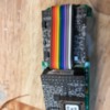
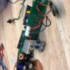
1st photo is the switcher with the original board.  I know all the hook ups here which at least is a good starting point.  The original board is clearly marked, "motor",  "lamps" and such.  I can see where the ground wires.  

The remainder of the photos is the Train America board.  The only hook up clearly marked on this one is for the motor.  I am new to TMCC so no expertise although I did just complete and ERR upgrade to an older Williams Brass Daylight with little trouble.  But I would be guessing on hook ups here.

Let me know on the photos.  I do have a camera with a macro lens and could take closer photos if needed.

Troy

Attachments

Images (6)
  • atlas sw9
  • TAm TMCC (1)
  • TAm TMCC (2)
  • TAm TMCC (3)
  • TAm TMCC (4)
  • TAm TMCC (5)

I'm going to guess that your SW9 is one of the very early models, made in Y2K or before.  This was Atlas' first venture into 3-rail O gauge.

When Atlas learned of 3-railers' appetite for spending big money on command control and gimmicky features, they scrambled their brains trying to figure out how to fit the necessary electronics into the tiny SW9 with its excellent HO-style cassette drive.  Not easy, but eventually they succeeded.  However in order to do it, they modified the frame.  I don't know what the exact modifications were, but apparently it was more than what amateur hobbyists could be expected to do for a home upgrade.

Just the same, they didn't want to leave those who purchased the original batch of conventional units behind.  So they offered a frame swap / frame re-machining service for a limited time.  And that time was up years ago.  So if you have a conventional model with an unmodified frame, you probably won't be able to install OEM electronics in the OEM configuration.

You MIGHT be able to install the smallest ERR command board with no sound.  Especially if you're willing to sacrifice the cab detail.  The stock speaker was nothing to brag about.  I'm not sure what the handrails are made of, or whether they're insulated on early conventional units.  That's an important question, because getting a TMCC antenna to work inside the die-cast cab is going to be another challenge.  I have one of these early units, and it's still conventional, but I'm mostly a steam guy these days.  Good luck!!

Last edited by Ted S

That's the bottleneck board that they made for that particular model.

If you look closely at the picture below, you'll see that the connectors are labeled.  I can only read a couple at this angle.  I believe the one between the couplers is the Antenna.

I can't read the one connector, but the other one says motor.


Attachments

Images (4)
  • mceclip0
  • mceclip1
  • mceclip2
  • mceclip3
Last edited by gunrunnerjohn

OK... It's raining here today so I'll probably take a look at this again.  Just to clarify, the one that has the motor clearly marked is the board that is in the unit right now.  All of those connections are clearly marked.  The board with TMCC is not clearly marked.  I understand better now that you pointed out some of them in the picture.  

1.  On the switcher.  I have a red wire coming from the roller pickup on the front truck, and a yellow coming from the rear.  Do those go to the "track power" connection that you note or is that were the motor wires should go?  (IN OTHER WORDS)... specifically where do the wires from the motor and from the pick up rollers go on the Train America TMCC board?

2.  On the switcher, there is a black wire that runs to a ground screw on the frame.  Where would that go on the T.A. TMCC unit?

3.  On the TMCC unit, what is the "extra" board connected by the rainbow wire ribbon?  Does that run smoke and couplers?  If so, I can leave that out and create more room for the install.

Thanks again!

Troy

(1) The track power black goes to the wheels (frame), and the red wire goes to the center track rollers.  The front and rear rollers are connected together to go to the red wire.

(2) I suspect that's the wheel connection for the track power unless there's a specific connection from the trucks.

(3) You need all three boards.  The board on the end of the cable is the RailSounds power board.

Pretty sure these are the motor on the TMCC board.

Attachments

Images (1)
  • mceclip0

Well dang... thoughts of swapping these boards out to get TMCC in here is looking like a pipe dream.  I have it hooked up and the unit runs conventionally.  It did not seem like the conections were "swiched".  Motor went to motor and the roller pick ups went to power.  TMCC signal is not being recognized.  I plugged a couple of small wires into the antenna spot but its not recognizing a signal OR could it be that one of those connections was a switch to turn on/off tmcc.  I have attached another photo.  One clearly indicates it is a switch connection, but for what?  Could be smoke for all I know.

Any idea on what the board is in front (tied to the unit with the ribbon connection)?

Also, can someone list a source to obtain those little white pin connectors used on these boards and what they are named?  There is not an electronics store anywhere close and would probably need a name to look them up on line.

Remember when you just sat a train on the track and it went?  Conventional is looking more and more attractive... maybe even key wind!


Troy

Attachments

Images (1)
  • IMG_1651

Add Reply

Post

OGR Publishing, Inc., 1310 Eastside Centre Ct, Suite 6, Mountain Home, AR 72653
800-980-OGRR (6477)
www.ogaugerr.com

×
×
×
×
Link copied to your clipboard.
×
×