


That sounds like more fun! I think you will really enjoy the benchwork part anyway, but it goes pretty quick.
Folks,
In case you didn't get an email, the buffers are ready to be shipped. Check your email and SPAM filters, and note that I sent a second message to correct bad math in my first message! ![]()
It's been a long road, but I see the station just ahead, we're through the tunnel with the mystery light up ahead! ![]()
For folks that would like a machine readable copy of the "final" documentation, here's a copy.
Attachments
Files (1)
Nice documentation! You do a real nice job of putting those all together, and color pics too!! (Got email, final pmt coming today, here in a bit)
Hi John. Just sent the balance payment to you.
Pat,
Thanks, however you missed the shipping. ![]()
Insured shipping charges in addition to the $90 remaining balance are as follows:
(1) Buffer, $12 - Total $102
(2) Buffers, $20 - Total $200
(3) Buffers, $20 - Total $290
(4) Buffers, $25 - Total $385
Hi John: Thanks for the buffer, I installed it on my 25'x50' 2 levels layout with 800' of GarGraves track, I run my K-line, 3rd Rail, TMCC, Legacy, Vision Line locomotives and they run flawlessly on both levels, going thru two home made aluminum bridges 4' long, no issues at all; the two LED's are On, one is blue and the other one is solid green all the time; thank you Manco (REP) and you, GOOD IMPROVEMENT, just awesome.
Churu posted:Hi John: Thanks for the buffer, I installed it on my 25'x50' 2 levels layout with 800' of GarGraves track, I run my K-line, 3rd Rail, TMCC, Legacy, Vision Line locomotives and they run flawlessly on both levels, going thru two home made aluminum bridges 4' long, no issues at all; the two LED's are On, one is blue and the other one is solid green all the time; thank you Manco (REP) and you, GOOD IMPROVEMENT, just awesome.
Churu: That's the news we like to hear. Thanks, cannot wait until I get mine. Ain't it GREAT !!!!
Success stories, that's the only kind we want to hear! ![]()
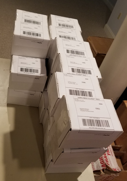
Seriously, that's great to hear, I'm happy they're doing the intended job. I'm busy prepping labels to ship 40 more, hopefully they go out today.
I was thinking to print the schematic and keep it with the the instructions. But I can’t find it, on the forum. Anyone have the link?
Yes folks, they're really being shipped! ![]() These will be going out today.
These will be going out today.
Attachments
Images (1)

Here's the latest schematic. I decided not to print 100 copies of the schematic for the shipments as it's easily obtained, and a vast majority of folks will have no use for it.
 Schematic")
Attachments
Images (1)
 Schematic")
Excellent, thank you.
Just got a notice that mine is in the mail.
Dropped a bunch of boxes off at the USPS, so a few folks should get some notices. ![]() I'm packing some more this afternoon, those will probably go out tomorrow.
I'm packing some more this afternoon, those will probably go out tomorrow.
MartyE posted:cjack posted:I was thinking to print the schematic and keep it with the the instructions. But I can’t find it, on the forum. Anyone have the link?
Like this? This version still had the schematic. John will have to verify if it is still up to date as I see he posted a newer document.
Thanks Marty, note that the schematic from GRJ is the later one with the caps across the opamp power pins. But much appreciated! I'm saving both with the instructions.
cjack posted:MartyE posted:cjack posted:I was thinking to print the schematic and keep it with the the instructions. But I can’t find it, on the forum. Anyone have the link?
Like this? This version still had the schematic. John will have to verify if it is still up to date as I see he posted a newer document.
Thanks Marty, note that the schematic from GRJ is the later one with the caps across the opamp power pins. But much appreciated! I'm saving both with the instructions.
Cool. Wasn't sure if it was up to date. Glad he posted. I'll delete mine so as to not to confuse anyone.
Hay GRJ,
Will get payment out this weekend to you, for $102.
Steam Forever
John
Just received my buffer today, Great work John.
I hooked it up and found out my Legacy base was bad, only .080 volts base input and 0.100 base output red led. and then hooked up to my cab Legacy and read a 1.140 volts base input and 3.916 volts base output no light on signal level,measured with fluke 87 meter. It look like my legacy is dead.
Thanks John. Received the Booster today. . I'll connect it this week. Great job!
I received an email notice that I will be getting a package from John Will, Thank you John.
Ray
A bunch of them are sitting on the porch for pickup, but they USPS has been somewhat unreliable lately at picking up. If they don't get them today, I'll drop them at the PO on Tuesday.
75 have been shipped, I'll be shipping the remainder this week. Of course, there are a handful of people that haven't yet paid the balance, those will rest in the "completed buffers" box for now. ![]()
John
thanks again. Mine came yesterday.
gunrunnerjohn posted:A bunch of them are sitting on the porch for pickup, but they USPS has been somewhat unreliable lately at picking up. If they don't get them today, I'll drop them at the PO on Tuesday.
75 have been shipped, I'll be shipping the remainder this week. Of course, there are a handful of people that haven't yet paid the balance, those will rest in the "completed buffers" box for now.
It's somewhat reassuring to hear I'm not the only one who has been the victim of USPS unreliability. I was told in email that not 1, not 2, but 3 packages were left on my porch 2 days ago and they were not there when I got home! Who knows if my booster will even show up this week??!!??
Greg
Jprails posted:Just received my buffer today, Great work John.
I hooked it up and found out my Legacy base was bad, only .080 volts base input and 0.100 base output red led. and then hooked up to my cab Legacy and read a 1.140 volts base input and 3.916 volts base output no light on signal level,measured with fluke 87 meter. It look like my legacy is dead.
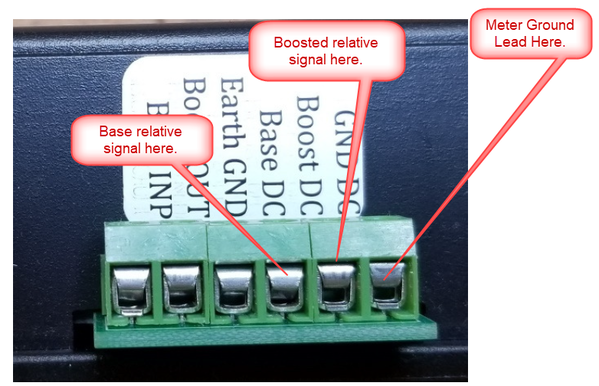
The thing to do is measure the base signal at the measurement ports on the buffer. Remember, the measurements are just a rough guide as converting the 455khz to DC incurs a lot of losses, specifically the diode drops make the lower level signals look worse than they are. I made readings on a known good Legacy base that was outputting around 5.4 volts of signal, those are what I put in the document. I also tried to make clear that this is not an absolute reading, and can vary from buffer to buffer based on component tolerances. There is no calibration of this value, it's really intended to be able to track the performance of an individual command base and buffer over time.
That being said, my experience does suggest that 1.140 volts measured here is probably low for a Legacy command base.

Attachments
Images (2)


gunrunnerjohn posted:A bunch of them are sitting on the porch for pickup, but they USPS has been somewhat unreliable lately at picking up. If they don't get them today, I'll drop them at the PO on Tuesday.
75 have been shipped, I'll be shipping the remainder this week. Of course, there are a handful of people that haven't yet paid the balance, those will rest in the "completed buffers" box for now.
You should get extra credit for just being able to keep track of all those things and who, where, when, etc. to send them to! ![]()
![]()
Former Member
John,
If any with unpaid balance are unclaimed I will buy one ![]() .
.
Thanks,
john balance just paid thanx herb
rtr12 posted:You should get extra credit for just being able to keep track of all those things and who, where, when, etc. to send them to!

Who says they're going to the right people??? ![]()
![]()
Christmas came early for me today, fished this out of the mailbox. Cannot wait to install this Buffer Kit. Thanks John
Attachments
Images (1)
I got mine up and running and really making a difference thank you
It's pretty complicated Roger, connect the power and three leads. ![]() Oh, you do have to put the tether between the command base and the command base power supply to tap off the earth ground, that's one of the three wires.
Oh, you do have to put the tether between the command base and the command base power supply to tap off the earth ground, that's one of the three wires. ![]()
I measured the voltage at the buffer.The Cab-1L legacy is the one that works on my layout with the buffer and I have seen an improvement in operation so far it good even with the 1.140 voltage. The legacy is not working at all I guess I will have to send it back again unless it can be fix by someone else. Thanks again for the help in getting my RR running again.
John,
Got mine this morning will hook up this week. Will let you know how it works, from the posts of others I am sure it will. You have done an incredible service for all of us.
Thanks,
Marty
Jprails posted:I measured the voltage at the buffer.The Cab-1L legacy is the one that works on my layout with the buffer and I have seen an improvement in operation so far it good even with the 1.140 voltage. The legacy is not working at all I guess I will have to send it back again unless it can be fix by someone else. Thanks again for the help in getting my RR running again.
Since the buffer drops the impedance and also boosts the P-P voltage, it'll make even a bad base work much better. Send the Legacy back to Lionel, they have all the parts and expertise to get it working again.
Are you measuring AC voltage right out of the command base or what? The voltages I speak of are on the buffer measurement terminals.
martind posted:John,
Got mine this morning will hook up this week. Will let you know how it works, from the posts of others I am sure it will. You have done an incredible service for all of us.
Thanks,
Marty
Thanks Marty. They worked when they left, and they're not all that shock prone, so I have high hopes that they'll work when they get there! ![]()
Mine came today. Thank you very much...
Currently, everyone that's paid up is either shipped, or sitting on the table behind me with shipping labels attached and waiting for the next mailing day, that should be Tuesday. I send out an email (or rather USPS does) when I create the label. That being the case, you're paid up, you should have either received it or gotten a notice that yours is shipping. If you haven't gotten either, and you think you're paid up, please contact me and we'll sort it out. I think my accounting is pretty good, but mistakes happen. ![]()
John, I received my automated shipping notice about 20 minutes ago. Thank you, your accounting works!
gunrunnerjohn posted:Currently, everyone that's paid up is either shipped, or sitting on the table behind me with shipping labels attached and waiting for the next mailing day, that should be Tuesday. I send out an email (or rather USPS does) when I create the label. That being the case, you're paid up, you should have either received it or gotten a notice that yours is shipping. If you haven't gotten either, and you think you're paid up, please contact me and we'll sort it out. I think my accounting is pretty good, but mistakes happen.
John I paid for two early this week and have received no notification
Greg Stack
Don't know why Greg, it was generated yesterday and the USPS has the package.

Attachments
Images (1)

gunrunnerjohn posted:Don't know why Greg, it was generated yesterday and the USPS has the package.
All good then. Thx.
John,
If you don't get the balance on some of those I'll take one.
Brad
Mine also arrived in this afternoon's mail. Everything looks great. Thanks again GRJ!
Yea baby mine arrived this morning. Hooked it up and it works great. Vision Legacy GG1 use to have problems with flickering lights and it would stop in a area with overhead tracks and metal bridges. Now with the booster it runs right along with no flickering lights. Thank you John!
gunrunnerjohn, John Will
I want to thank you so much. I have had an area on my large layout that at times gives me a PITA. I have been messing with this part of the layout for over a year. Some days it works when it wants to and other days not at all. I have been down at the layout, installed your Buffer and that area has no problems at all...in fact the trains run better than ever after I installed your Buffer. I have NO problem with the costs of this little jewel, it is a miracle for my layout. Thanks so much for your and Dale's knowledge.
I am going to build a building for the layout and name it Dale & John's Buffer Company. ![]()
My experience with the booster:
Connected the booster as shown.
Powered up the system.... Legacy base dead... Oh No! Must be a bad power adapter... Happen to have another... Changed the power adapter... Same problem! Checked the adapters, no power..!
Ok so what is the problem... Checked the earth ground adapter cable...SHORTED
SOOO... Replaced a blown fuse in the Legacy Power Adapter, and repaired the shorted earth ground adapter cable. ( red center wire melted to the outside frame of the connector during soldering.)
OK... So lets try again!
Reconnected all and the Legacy base comes alive... The status indicator on the booster shows green! YEA! Read the DC reference voltage on the input side... It is 1.6V and on the output side, 5.9V.
OK Now lets runs some trains! Trains that previously had experienced problems in certain areas appear to function normally..!!! YEA it works.
Thanks John for a great addition to the hobby
-----------------------------------------------------------------------------------------------
But as an aside, you might want to check the adapter cable before powering up to prevent a blown TMCC adapter.. (Luckily the Legacy adapter comes apart and you can change the fuse.)
Terry
The initial problem was the shorted ground adapter cable which blew the fuses in the legacy power supply!
Great that it's working, I'm clueless to what your problems were, so what caused the initial problems!
Installed my booster today. Got red led light indicating bad signal. Checked base in voltage 0 .166 mv and buffer out of .661 volts. Interestingly, problem locomotives ran better. Will call Lionel tomorrow, hope they will repair it.
Marty
martind posted:Installed my booster today. Got red led light indicating bad signal. Checked base in voltage 0 .166 mv and buffer out of .661 volts. Interestingly, problem locomotives ran better. Will call Lionel tomorrow, hope they will repair it.
Well, the red light appears to be working correctly, with those readings you do have a bad signal! ![]()
BlBillboards posted:Ok so what is the problem... Checked the earth ground adapter cable...SHORTED
Bummer about the earth ground tap, sorry about that. All of the cables did actually test good before they went, but obviously that was marginal. I'll blame that one on my assistant... Wait, I didn't have an assistant!
Well, at least it came to me and I was able to repair!
Terry
Hi John,
Just to let you know I received my TMCC buffer yesterday, and installed this afternoon on my layout. Getting a green light all the time as indicated on the buffer . I have not done any actual signal voltage measurements yet. My layout is approx. 35 x 12 with 2 track loops around; had a few minor problems with the old setup without the buffer-- the new buffer signal seems to be perfect!!!
Thanks again for doing all the follow-up design to Dale's original design and getting the new boards made and shipped out. That was a very large undertaking!!! I am going to be anxious to hear feedback from some of the large layouts on how the buffer is helping their TMCC signals. I suspect a few of the large layouts I see at the Milwaukee Train Fest every November will work much better with more reliable operation too.
Thanks so much!!!
Regards,
Carl J
We love success stories! ![]() Since the NJ-HR use it and apparently it solves most of their TMCC/Legacy issues, I suspect most layouts will work well with it.
Since the NJ-HR use it and apparently it solves most of their TMCC/Legacy issues, I suspect most layouts will work well with it.
96 of the first 100 units have been shipped, so almost everyone that was in on the initial batch should have one within a couple of days.
I received my TMCC Buffer, however, haven’t installed it, but, I do have a HUGH SUCCESS Story, Farmerjohn, a Kentucky friend of mine, has a really large layout, 50 by 70, with an an adjoining room, who has had multiple signal issues, running TMCC/Legacy, Atlas O. Third Rail/Sunset Models, through many bridges, multiple levels, says All his engines Run Fine Now, Do to the TMCC Buffer. Dale Manquin came to visit me here in Tennessee in 2007, prior to York, and we went to see many layouts, one being Farmerjohn’s in Kentucky. Dale was a very fine gentleman and stayed at my home for a week. We had a great visit. I congratulate Gunrunner John for taking his concepts and making this wonderful product available to us Operators. Thank you John....I will install my Buffer in the next few days. Happy Days are here again. (Pictures are of Farmerjohns latout)


Attachments
Images (9)
Wow, 50 x 70, now that's a LAYOUT! ![]()
Hi Larry-
Thanks for posting all those pictures of FarmerJohn's huge layout!!! And the fact that the TMCC booster/ Buffer original design has been working so well on his 50' x 70' layout in Kentucky!! I can only imagine the length of time and number of people needed to get the layout to the point that was shown in your pictures!! Fantastic layout!!!
Carl J
Got my DM buffer, now looking for a place to put it, anxious to get it hooked up.
Thank you John
Ray
Hi Carl, Farmerjohn has been working on this layout for probably 7 or 8 years, with a really great wood worker and Friend. He works many hours daily on this adventure and keeps everything clean as can be. They have devised many neat features on his wonderful layout. 10 stall roundhouse with individual opening doors. A MILLHOUSE 34 inch TT. A signal system overhead signals, track level signals. A wonderful Oil Refinery, and new Mining System, above and below ground. One feature is 4 or 5 trains can be running and there’s is no way to figure out their route. Amazing thinking, and a fun to visit friend. Always something new to view and enjoy. He runs TMCC- Legacy Cab1L, Cab 2.....His wide radius curves, 0120 and more, no less than 080, allows for long freight and passenger trains to interwind with each other. Thank you for your comments and someday, come to see us. 


Attachments
Images (6)
That's the kind of layout most of us can only dream about. ![]()
I really have to thank John again for pursuing this project and carrying on where Dale left off. I also want to thank him for donating back in Dale's name. It's just another reason I find most train people are mostly made up of the good stuff.
Speaking of that, I almost have all the payments in and the buffers shipped, so I will be sending out the contribution in the next few days, I'll post when it's completed.
I'd still rather have Dale around to see his great project finally cross the finish line.
leapinlarry posted:I received my TMCC Buffer, however, haven’t installed it, but, I do have a HUGH SUCCESS Story, Farmerjohn, a Kentucky friend of mine, has a really large layout, 50 by 70, with an an adjoining room, who has had multiple signal issues, running TMCC/Legacy, Atlas O. Third Rail/Sunset Models, through many bridges, multiple levels, says All his engines Run Fine Now, Do to the TMCC Buffer. Dale Manquin came to visit me here in Tennessee in 2007, prior to York, and we went to see many layouts, one being Farmerjohn’s in Kentucky. Dale was a very fine gentleman and stayed at my home for a week. We had a great visit. I congratulate Gunrunner John for taking his concepts and making this wonderful product available to us Operators. Thank you John....I will install my Buffer in the next few days. Happy Days are here again. (Pictures are of Farmerjohns latout)
Look at that scene! In the famous words of Mr Barone, "HOLY CRAP!!!"
And as mentioned a big thanks to John for seeing it through to completion for all of us!
Larry,
thanks for posting the additional pictures and comments on FarmerJohn’s layout. The pictures continue to blow me away!!
Do you know where the TMCC signal was originally weak or intermittent and did the newly designed Buffer/ Amplifier installation immediately resolve all the operational TMCC signal issues?? I hear from others that track going across bridges or going through secenery made with wire screen or track going over / under other tracks are “weak signal points “ that seem to get solved with the TMCC Buffer??
Carl J
Carl J, the answer, from what I am hearing from Johnny, he gets a great signal in the entire room and the adjoining room now. Before the Buffer, only partial TMCC signal intermittent in the main room, but would allow some trains to run ok, others not ok, however, no legacy signal in the adjoining room. Its very discouraging to buy a top of the line Locomotive, or Diesel and it not run good do to signal. This is the best answer I can give you until I go to visit Johnny. Now he can run everything that’s TMCC/Legacy with great control anywhere in his train room. This TMCC Buffer is the best thing, since sliced bread.....
Another satisfied customer! Connected the DM TMCC Buffer and got a green light! ALL my TMCC/Legacy engines run everywhere on my 1000 sq. ft. multi level layout. I had talked to Dale about the buffer before he died and I am so appreciative to gunrunnerjohn for picking up the project. The recognition given to Dale is so appropriate.
Don
The larger the layout, the more benefit you can expect from the DM TMCC Buffer. It's good to hear success stories. ![]()
Thanks Larry!!
John, hooked mine up 10 minutes ago and the indicator light is green. Hooahh.
Put the loco I had the most signal problems with, blinking lights, stopping, etc., my Lionel UP Veranda.
It runs perfect through all the previous problem areas.
Thank you John and Dale.
You have turned my problem locos into great performers.
One question, can I leave it powered up 24/7 or should I turn it off between operating sessions?
Getting some encouraging feedback. I hope the kit we be available soon, with a candidate to assemble mine! Of course for a fee.
Jeff, other than using a few watts of electricity, I can't imagine why you can't just leave it on.
ironman1 posted:Getting some encouraging feedback. I hope the kit we be available soon, with a candidate to assemble mine! Of course for a fee.
I'm actually gathering parts for the kits, and I have the PCB blanks already. We'll have a solution for folks that missed the first production run. I just have to figure how they'll be packaged. Right now my thinking is that I'll prep the cases as I already have the tooling to do that, and individuals would probably take a lot more time to drill the holes in the proper places as well as make the slots, etc.
There will be an option. ![]()
Hi John,
Thanks again for this project. I just hooked the buffer up and got a RED light. I did run some engines that were always susceptible to interference like my K-line 2-6-6T and it had NO flicker at all with good response of commands.
The readings I got were: base signal - 1.085, output signal - 10.37. Any thoughts on what I should do/check?
Thanks,
Greg
The base signal is low (reason for the red light), but the output is uncharacteristically high. Based on your input, the output should be about 3.6vdc.
Something wrong with your metering? And things run better because 3.6 is an improvement.
Gregcz1 posted:Hi John,
Thanks again for this project. I just hooked the buffer up and got a RED light. I did run some engines that were always susceptible to interference like my K-line 2-6-6T and it had NO flicker at all with good response of commands.
The readings I got were: base signal - 1.085, output signal - 10.37. Any thoughts on what I should do/check?
Thanks,
Greg
First off, is this a Legacy or TMCC base? The TMCC base will usually get a red light and a few of them get the "no light". A good Legacy base should give you a green light.
I agree with Chuck, something is very wrong with the readings, with a known good Legacy base I got 1.88 volts DC for the Base DC reading and 5.4 volts for the Boost DC reading. Given the circuitry there, that's about what you should see. 10 volts on the Boost DC reading is knocking on the door to impossible! What kind of meter are you using?
I have a question about the light being red for lower output. What is drawing down the output signal 3.810volts to the track? When I unhook the track wire I get a green light and 6.15 volts out of buffer.
I'm confused. The lights are telling you what the base track output is doing, not the buffered output. If you're using the buffer, you shouldn't have the base track output connected to anything but the buffer input!
I'm getting 2.077 Base INP and 6.85 Boost OUT. I looked right down into the blue LED and after a half hour I can see again ![]() . So I ground the tops of the LEDs off on the sander. Diffused now.
. So I ground the tops of the LEDs off on the sander. Diffused now.
Thanks again John. Great stuff and hard work for you. I appreciate you.
gunrunnerjohn posted:I'm confused. The lights are telling you what the base track output is doing, not the buffered output. If you're using the buffer, you shouldn't have the base track output connected to anything but the buffer input!
The instruction is an excellent pictorial of the hookup. That should clear things up for him.
I have to admit, the clear LED's were possibly a mistake, those suckers are bright! ![]() I wanted to make sure they could be seen, I guess I did accomplish that goal.
I wanted to make sure they could be seen, I guess I did accomplish that goal. ![]()
They're fine. I thought about little opaque booties...or maybe an opaque lens snapped into the enlarged holes. But the sanding tamed them right down.
Well opaque booties would seem to really tone them down, easier would be black electrical tape. ![]()
![]()
Sanding the ends will certainly diffuse the light and save the eyes, probably the easiest method. ![]()
Hi John
I got the green lite and as Leapin Larry said earlier engines are running great where they never did before. I've gotten out old TMCC and they have no problems. My readings are off though 1.67 on the base DC 1.15 on the Boost DC, its an old. craftsmen multimeeter. Its plunged. Into my Legacy. Base
gunrunnerjohn posted:Gregcz1 posted:Hi John,
Thanks again for this project. I just hooked the buffer up and got a RED light. I did run some engines that were always susceptible to interference like my K-line 2-6-6T and it had NO flicker at all with good response of commands.
The readings I got were: base signal - 1.085, output signal - 10.37. Any thoughts on what I should do/check?
Thanks,
Greg
First off, is this a Legacy or TMCC base? The TMCC base will usually get a red light and a few of them get the "no light". A good Legacy base should give you a green light.
I agree with Chuck, something is very wrong with the readings, with a known good Legacy base I got 1.88 volts DC for the Base DC reading and 5.4 volts for the Boost DC reading. Given the circuitry there, that's about what you should see. 10 volts on the Boost DC reading is knocking on the door to impossible! What kind of meter are you using?
My "control" system is a Legacy Base which is also hooked up to a TMCC base. My testing meter is a Sperry DM-4400A. Now, today, I just retook the measurements and got .918 for base signal and 3.63 for Boost signal (but that reading was where it finally stop dropping after a minute originally registering at 4.2 v.
I disconnected the command base from the Legacy Base and got similar readings.
Does this mean my Legacy Base is faulty? If so, is there anything I should look for to fix or must it be returned to Lionel?
Thanks,
Greg
The lights and the DC output voltage are a very simple rectifier circuit that then feeds the DC output terminal and a voltage divider to drive the bi-color LED. In my testing I verified the actual input base voltages that the would trigger the red and green lights. I spot checked some of the buffers DC outputs, though given the light performance, I didn't expect them to be off. The red light starts coming on right as the base PP signal goes below 4 volts, and the green light starts to illuminate around 5.26 volts. Those numbers typically varied by around 5%. I will say, if you get a red light with a Legacy base, I'm 99% sure you have a low signal output that should probably be addressed. The only way to be sure is to measure the actual command base output signal.
All the voltage measurements were done with a Fluke 8012A bench meter, the 'scope measurements were done using the ATTEN ADS 1102CAL digital 'scope. The test "base" signal was 455khz from an HP 3311A Function Generator. In the development, I verified the operation with a couple of the original TMCC bases, one BASE1L, and a couple of Legacy bases. That was to insure that my test setup would reflect the real world. Obviously, I couldn't use a real command base for the actual production testing as I had no reliable way to vary the voltage from the base to test the buffer response at various signal levels.
I remember that Dale had spent significant time talking about the measurement using a similar diode circuit and in fact was including a cheap HF multimeter to get consistent results with every kit he produced to measure the TMCC/Legacy base output voltage.
I'm thinking maybe we need an independent cheap TMCC/Legacy test board just to verify the actual output of the command bases.
"I'm 99% sure you have a low signal output that should probably be addressed."
How do I do that?
I am sure it is the Legacy Base, because I hooked up the buffer to the TMCC Command base and the buffer flashed green for a quick second and then went out. So that seems to be "behaving" the way you described.
Well, Lionel is the folks that can address low output of the Legacy base. If you know someone with a 'scope, you can measure the output objectively.
I thought to further this discussion, I'd post a few waveforms that illustrate how I tested and why I felt the signal generator was a suitable replacement for the command base to test the buffers. ![]()
As you can see, all of the bases and my test generator put out a similar clean waveform.
HP 3311A Function Generator Output

Good Legacy Command Base Output

Bood TMCC BASE1 Command Base Output

Attachments
Images (3)


Gregcz1 posted:"I'm 99% sure you have a low signal output that should probably be addressed."
How do I do that?
I am sure it is the Legacy Base, because I hooked up the buffer to the TMCC Command base and the buffer flashed green for a quick second and then went out. So that seems to be "behaving" the way you described.
I've seen a couple "low output" Legacy bases. I don't know what is fragile on their output circuit, but Lionel can and does fix it free.
If were looking for a low cost handheld oscilloscope to measure the output signal of either a Legacy Base or TIU would this $25 one work??
New Assembled DSO150 2.4 inch LCD Display Digital Oscilloscope with Probe
eBay item number:
222948398748
OR
NEW ATTEN GRATTEN GA1102CAL 100MHz 2CH Digital Oscilloscope 7" LCD 1G Sa/s
This one is $300 but with what I spend on trains this $$ is not much of an issue.
Obviously, the ATTEN one would work fine, but the DSO150 doesn't have the bandwidth in reality. You want a bare minimum of 10x the sampling rate of the signal you're measuring, and the sampling rate of the DSO150 is 1Mhz, a 2x sampling rate.
The ATTEN is very similar to the one I use, AAMOF, I suspect it's the same one with slightly different panel markings. All the controls look identical as well as the bandwidth and sample rate.

Attachments
Images (1)

And the DSO150 has an analog bandwidth of only 200 KHz. I have a DSO 068 which is a great little handheld OScope and has a bandwidth of about 3MHz with equivalent time sampling rate of 20MHz which would work for this repetitive waveform. It’s a kit, so it’s even more fun...but there are similar non-kits if that kind of fun is not in your desires. JYE Tech is the company.
Yep, but I have to say, if you're going so spend $70-80 and hours of construction for a kit 'scope, why not spend $200 or so and have a 50mhz dual-trace 'scope? There are a lot of times I find the dual trace to be very useful, and wish I had even more traces. ![]()

Attachments
Images (1)

Got everything wired up got the green. I have two questions, 1 do I need to have the legacy base above the track level and 2 can I link the TMCC base and the Legacy base together? Thanks Bill
Billsrr posted:Got everything wired up got the green. I have two questions, 1 do I need to have the legacy base above the track level and 2 can I link the TMCC base and the Legacy base together? Thanks Bill
The only thing having the Legacy base above track level or line of sight is base to remote communication is better.
The TMCC base and Legacy base being connected via the supplie Y cable that came with Legacy should have zero to do with the booster. When connected like that, the TMCC base sends its information serially to the Legacy base. The Legacy base then sends that info to the track. Do not connect both Legacy base and TMCC base to the track or booster from the U connection. Just the Legacy base.
The only other precaution is not to put the buffer right next to the Command bases, give it a few inches of space. Also, don't bundle the buffered track signal and the TMCC/Legacy base signal, I had a report that caused crosstalk and scrambled the signal. Since they're in phase and one is three times the amplitude of the other, I can easily see how that could build yourself an oscillator if there's enough of a run right next to each other. ![]()
gunrunnerjohn posted:Yep, but I have to say, if you're going so spend $70-80 and hours of construction for a kit 'scope, why not spend $200 or so and have a 50mhz dual-trace 'scope? There are a lot of times I find the dual trace to be very useful, and wish I had even more traces.
Yes, good point. I buy kits for kit fun. I have a Rigol that looks like your scope for daily use. Also a Tek 2215 on a cart for easy use off the bench.
I really like the Rigol line, if I had it to do again, I might spend the extra $100 and get one of those. OTOH, my ATTEN has worked well and does everything I need it to do. Of course, I would like four traces at times, but I'm not willing to pay for them. ![]()
MartyE posted:Billsrr posted:Got everything wired up got the green. I have two questions, 1 do I need to have the legacy base above the track level and 2 can I link the TMCC base and the Legacy base together? Thanks Bill
The only thing having the Legacy base above track level or line of sight is base to remote communication is better.
The TMCC base and Legacy base being connected via the supplie Y cable that came with Legacy should have zero to do with the booster. When connected like that, the TMCC base sends its information serially to the Legacy base. The Legacy base then sends that info to the track. Do not connect both Legacy base and TMCC base to the track or booster from the U connection. Just the Legacy base.
Thanks, Does that mean that I wont be able to use the cab 1's.
It means you can use the Cab 1. The Cab 1 talks to the TMCC base and the digital output (DB9 connector) from the TMCC base goes into the digital input (DB0 connector) of the Legacy base. Then the Legacy base sends the signal out to the track...or in this case to the booster and then to the track.
Not at all Bill. When you connect the BASE1 to the Legacy base, that enables the CAB1 to send commands over to the Legacy base and out to the track. The buffer doesn't change any of that wiring, just leave it as is.
- The only thing you do to install the buffer is remove the wire to the track from the Legacy base and connect track to the buffered output.
- Connect the legacy base track output to the buffer input.
- Finally, install the tether and connect the loose wire to the Earth GND on the buffer.
The buffer is installed ready to do, plug it in and away you go.
The cab one controllers don't function only the legacy remote. Cable between the legacy and tmcc base are connected and buffer is wired up as described. also new batteries in the cab one remote. Any ideas.
Good, news, I installed the DM Buffer and all the weak signal issues in the freight yard are gone! But there is some interesting news. First a little about the layout for background. It is S gauge, about 800' of track on 4 levels, 4 reverse loops with electronic auto reverser boards. Power is 8 independent power districts, each fed by one handle of a pair of ZW-L's. One Legacy base, 37 LCS modules. There are about 40 blocks spread across the 8 power districts, each block has both rails isolated since it is 2 rail. There are 25 .1microfarad capacitors across the 2 rails to assure all blocks have the Legacy signal on both rails. All the track has aluminum tape under it for good signal.
When powered up the indicator appears solid red with flashing green. It flashes green irregularly but about 5 flashes/second. Voltage measures about 1.5V in and 3V out. Works that way with any one or all of PD's one through 7 powered up with voltage on the rails. The Legacy signal is perfect all over the layout. When I power up PD 8, singly or with other power districts the indicator goes solid green, the output voltage jumps to 15V, then over about 10 seconds it slowly ramps down to 11V and stays there. The input voltage does not change. What is really interesting is all the occupied track blocks in PD8 are unpowered at this point when I measure this high output voltage because the BPC2's controlling them are off. The trains run perfectly all over the layout. PD 8 is a 6 track passenger yard, an 8 stall roundhouse, 3 turntable feeder tracks and the rails on the TT. My initial thought was this is related to the auto reverser board that feeds power to the TT rails but thinking more about it I do not feel that is possible. As long as the system keeps working I am not going to worry about it but it sure is puzzling.
I have a second higher quality meter I need to find to get a second reading of the absolute voltages, but the voltage out definitely increases based on the indicator light.
Add Reply
Sign In To Reply
