


I am interested in purchasing. Can you add me to your list?
casconi posted:I am interested in purchasing. Can you add me to your list?
Ditto Please add me
John,
Finally built the kit but when connected and turned on, power light is unlit, the other LED is red, and after five minutes or so, the heat sink is not warm. Where should I start checking things? The output readings are low. TMCC is connected to Legacy via the serial cable.
Terry
If the power light doesn't come on, that's pretty basic! Since you have a red light, you're getting power, I'd say the power LED is in backwards.
Top suspect is the output amplifier having shorts between the pins. They are VERY close, and it's very easy to short them without knowing it happened. Use an ohmmeter to check between adjacent pins and make sure none are shorted.
As far as the signal, lots of stuff could have affected the signal. Do you have anything like a 'scope to look at what's happening in the circuit?
John,
Flipped the power LED, works now. Checked for solder bridges on the output amp and found none and it still doesn't get hot or even warm.
Terry
Well, my next step would be to doublecheck all the soldering as well as the component placements. It's pretty hard to troubleshoot a circuit long distance.
This is, of course, why I lean to doing the fully assembled/tested model, I know it works before it leaves.
John,
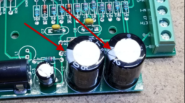
After a closer examination of the board, it seems I installed C3 backwards. Since there is a slight bulge on its top, I assume a replacement is called for.
Terry
That probably didn't do it any good! ![]() Send me an email with your address and I'll send you a replacement. In looking at the circuit, I wouldn't expect that to cook anything else, but I could be wrong. Actually, with the usage of that particular cap, I'm surprised it cooked, it actually has very little voltage across it in normal operation. I'd actually expect the buffer to probably work, at least for some time, with that one in backwards. I'd look around for any other component issues, for sure check C1 and C2 for proper orientation, they will greatly affect operation!
Send me an email with your address and I'll send you a replacement. In looking at the circuit, I wouldn't expect that to cook anything else, but I could be wrong. Actually, with the usage of that particular cap, I'm surprised it cooked, it actually has very little voltage across it in normal operation. I'd actually expect the buffer to probably work, at least for some time, with that one in backwards. I'd look around for any other component issues, for sure check C1 and C2 for proper orientation, they will greatly affect operation!
Specifically, note that the stripe on both of these faces the power jack.
Attachments
Images (1)

Done. Thanks. The othe 2 were fine.
Terry
Folks, I've had several kits come back to me with issues to solve, and usually it ends up that they were soldered with what appears to be acid core solder. THAT'S A GIANT NO-NO FOR ELECTRONICS! You must use a noncorrosive flux, the standard is rosin core solder. I use the 63/37 Kester Rosin Core solder for my electronic work. Save the other stuff for plumbing!
I have a couple of the final sets that I've assembled and tested on the shelf if anyone is still looking for one of these.
ACID core solder!! Ohmigod, unbelievable. I don't know if you can even buy rosin core solder at Home Depot or Lowes; maybe not?
John, maybe it would be wise to include a small 2 or 3 foot long chunk of rosin core solder wound up with each kit, like Heathkit used to do? Then it would be hard to screw up. ![]()
Rod
That would have been a good idea, but I'm winding this down now, I have a handful of parts left for a few more units and I'm done. When I get some spare time, I assemble one or two and put them on the shelf.
I still have to come up with a nice package of documentation so going forward after my parts run out someone could duplicate the buffer, don't want the process to get lost.
OK - I cringed when I seen Acid Core solder!!! Does Acid Core even come in a small enough diameter to be able to solder PCB components?? (Even though its a bad idea)
For Smoke Units I do use the high temp solder (No it's not Acid Core).
Jim
Rosin core solder is available at Lowe’s & Home Depot, in both thick & thin gauges.
Tom
I built a lot of Heathkit devices over the years. Everything from a color TV to stereo components to test equipment. I always remember the warning that Heathkit had on the 1 st page of the assembly manual. Kits returned for repair or troubleshooting that have been assembled with acid core solder or fluxes will be returned without repair and warranties are void. Use only rosin core electronic solder. Heathkit even went as far as including a coil of solder they wanted you to use with the kits.
I am just reading this forum for the first time - my loss at being late to the party. Is it still possible to get one of these? Thanks!
Gunrunner.
These buffers are the best thing ever for a large multi level layout. It has cured so many problems that I had. I now run logos that I was go g to sell because of signal problems. I bought 3 of these units just in case lighting strikes I still have one i need to put a pot in . Thanks.
John, the gerber files and components list would be great!!
One item we have started doing is to use a socket for the eprom for easy swap, we have 3 of the kits left, and have secreted the unit under the layout so it can not be unplugged. The units we lost to electrical overload from the ac/dc plugs being swapped lead to this change.
sandysimon posted:I am just reading this forum for the first time - my loss at being late to the party. Is it still possible to get one of these? Thanks!
I still have a few sets of parts, so I can still supply them.
Ron_S posted:One item we have started doing is to use a socket for the eprom for easy swap, we have 3 of the kits left, and have secreted the unit under the layout so it can not be unplugged. The units we lost to electrical overload from the ac/dc plugs being swapped lead to this change.
Ron, what EPROM? There are no programmable parts in the TMCC buffer.
Sorry John, In my head they were eproms, my bad. The AD744 and LM chips are what we socketed.
You had me confused Ron, I thought you might have redesigned the buffer while I wasn't looking! ![]()
John,
I'll send an email. I would like to purchase a kit of one of these. Thanks again for all you do for us in the hobby.
Dave Goodman
dave.goodman@msn.com
GRJ, thanks for the heads-up on limited availability on this. I'll take a fully assembled unit, if any left. Thanks!
Ron
Send me an email and we'll fix you up.
John, I totally respect you for your dedication to this group, "WOW!". How many of us would take on a project like this to help others? You and the late Dale M. fantastic people.
Thank you and God bless you
Ray
If you can - send me one - thanks
ted
John send me info for the booster and I also have at least one engine I need your help repairing. Thank you!
Folks, I have two kits left, and that's all. If someone is really wanting as assembled unit, I can build one or both of the kits, again that would cause a delay as I do them as I get time.
If there's really a lot of interest in more, I can order more parts, but it'll take some time as I need more PCB's, boxes, and power supplies, those take a few weeks. Obviously, the Digikey parts come in a couple of days.
Hi john
can you build one of the kits for me
thanks Rich R in
Please send me an email.
John
i just sent you an email for the kit build
thanks Rich R
Can you build another one for me please?
I have more parts on order, but since stuff like the power supplies and plastic enclosures come from overseas, it'll probably be 2-3 weeks. I also have to prep the cases with the holes and slots. I'll post here when more are available.
Hi John - I'm not in a rush and would take an assembled unit whenever ready. I think I e-mailed you earlier this week.
Thanks.
Got you in the queue Richie. ![]()
Gunrunner John, Question, does this kit help the Cab 1, Cab 1L, Legacy Remote, have better control of the engines at far corners of a layout? Specially if the trains in a part of the layout 15 feet away from the TMCC/Legacy bases? Sometimes my Cab 2 loses control of the engines. Just wondering if this is the fix. Thank You very much for all you do for our hobby.
No, this has nothing to do with the link between the remote and the command base, it's affecting the track signal out of the base to the layout. The RF link between the remote and command base is a whole different conversation. ![]()
@leapinlarry posted:Gunrunner John, Question, does this kit help the Cab 1, Cab 1L, Legacy Remote, have better control of the engines at far corners of a layout? Specially if the trains in a part of the layout 15 feet away from the TMCC/Legacy bases? Sometimes my Cab 2 loses control of the engines. Just wondering if this is the fix. Thank You very much for all you do for our hobby.
Larry, I had a dead spot on my track that I could not overcome. It developed over a period of time. I tried everything.....I purchased this booster for John, and it was the best $$$$ I have ever spent on my layout. Well worth the investment.
@Roger Wasson posted:Larry, I had a dead spot on my track that I could not overcome. It developed over a period of time. I tried everything.....I purchased this booster for John, and it was the best $$$$ I have ever spent on my layout. Well worth the investment.
That's the problem that the buffer addresses. The link between the remote to the command base sounds like what Larry is asking about, the buffer won't help with that issue. For a CAB2, I've used a hi-gain antenna on the command base, and on one instance, I actually used a 2.4ghz WiFi amplifier on the command base. That really increased the range, and for really large layouts, it would probably be a significant help.
John please confirm you got my request for an assembled unit. This was the first time I used the private communication thing. Thanks George
Look at your profile, I even answered you there. ![]()
Larry, the very first thing to try is changing channels! I'd try 1, 5, and 9 first, then try the intermediate channels. It could be something interfering, like your home WiFi router. If that doesn't do it, then you start talking about amplifiers.
Gunrunner John, I’ll do that, thank you very much. I deleted the other pictures as it was just to show you the front and back. Happy Railroading
Hello, I have not started my layout yet, but have the design done. Just finishing the room where it all will go. The layout is 32' long and 13' wide. I'm very new to all of this so I will admit I'm ignorant to all the electrical things as of now. So, how does this all work? Will it help me in the long runs I have? Cost? I can send a picture of my layout if you need to evaluate my need. I have a large collection of MTH and Legacy Lionel. Thank you Bob Huntnfish737@hotmail.com
Bob, I doubt you'll need the booster unless it's an unusual configuration, usually it's large and multi-layer layouts that end up with TMCC/Legacy signal issues.
BTW, what do you fly?
Capt. B767 and B757
Also, I'm looking for a #4023 Bigboy....if you know of one available, let me know. Thx Bob
@Boeingman posted:Capt. B767 and B757
I saw the stripes, but I didn't recognize the cockpit. ![]()
I haven't seen many BigBoy's floating around, I did have a couple extra a while back, but I sold them when they went up in price.
@Boeingman posted:Capt. B767 and B757
Gold stripes...Delta, or former Continental? AA is parking all of our 757s, so I’ll never get the chance. Bummer...
I’m stuck with the bus calling us a retard every time we land.
Tom
ExCon
I'm former North Central (1978), then through mergers: Republic Airlines, then Northwest, then Delta. Four different uniforms in the closet. I retired off the 747-400 three years ago. I flew the 747 for almost 10 years and it was a real kick, but my most favorite in my 39 year career was the 757. Northwest only had the 757's, but after the merger with Delta got to fly the 767 also. Same type rating, and we would see a mix of both on our rotations. I think most of the 757's and 767-300's are now parked. Only the 767-400's are being used. If I could go back and fly one more trip, it would be on a 757. Unfortunately, only in my dreams....
@Jack Morey posted:I'm former North Central (1978), then through mergers: Republic Airlines, then Northwest, then Delta. Four different uniforms in the closet. I retired off the 747-400 three years ago. I flew the 747 for almost 10 years and it was a real kick, but my most favorite in my 39 year career was the 757. Northwest only had the 757's, but after the merger with Delta got to fly the 767 also. Same type rating, and we would see a mix of both on our rotations. I think most of the 757's and 767-300's are now parked. Only the 767-400's are being used. If I could go back and fly one more trip, it would be on a 757. Unfortunately, only in my dreams....
Did you ever operate out of Minneapolis? If you did, you very likely knew my aunt. She has been with Northwest/Delta since 1975, and will be retiring next spring.
I was never based in MSP. Flew through there hundreds of times, overnighted numerous times. I was based in Chicago until the crew base closed in 1984, then flew out of Detroit. Never lived in Detroit, commuted there from Florida. I’m sure I probably would recognize her. Was she a gate agent or flight attendant?
She did a bunch of stuff... gate agent, ground traffic, flight simulators over in Eagan. Susan Tennis is her name.
John, quick question, finally hooked my booster and if fixed my issue of having a bad signal on a piece of track that i was using as an insulated rail. One question, i have one of the newer ones that have a pot on it. The printed instructions did not talk about it and i did not was to go through 19 pages here. I am guessing it is for the signal, but how does it work?
Tony, that's a good question. I never got around to documenting that as it was a late addition. It does indeed vary the amplitude of the TMCC signal. This allows you to "tune" the signal to minimize any interaction with DCS and also to reduce the amplitude if you have issues with stuff like LCS Sensor Tracks.
Even with the signal turned down to minimum, the buffer is still providing a substantial benefit, it gives the TMCC signal much lower drive impedance so that it can drive more track capacitance. There are people that run it at the minimum with good results, it fixes their signal issue at that level.
The way to use it is simply turn it down as much as possible while still solving any TMCC signal issues, that will insure the maximum compatibility with device that may react poorly to too much TMCC signal.
Just to make sure, which way is less, left or right?
CCW is lower, CW is higher, just like your radio volume control. ![]()
I had to turn mine down a bit because of the interference to a sensor track. I just adjusted it until the sensor worked again.
So the original run did not have this adjustment capability?
It wasn’t a big issue, some of us just added a pot and John added it to his product at about the same time
@Stackm746 posted:So the original run did not have this adjustment capability?
Nope, it wasn't until a bunch of them were in the field that we started getting reports of them affecting the DCS signals. Then Jon Z. chimed in and said the sensor tracks would have a problem with too strong a TMCC signal.
Thus the amplitude adjustment feature was born.
I am just installing DCS and am having issues. Is there a way to retrofit?
@Stackm746 posted:I am just installing DCS and am having issues. Is there a way to retrofit?
Send me an email and I'll send you the instructions and the parts required. It's an easy retrofit.
I'm Interested in getting one for my barn layout I'm planning. 6 different levels spread across 2 storys (5000 feet of track). So I'll most definitely need one. How much do they cost though?
that would be something to operate on
@APW Trains posted:I'm Interested in getting one for my barn layout I'm planning. 6 different levels spread across 2 storys (5000 feet of track). So I'll most definitely need one. How much do they cost though?
It will be the Cheapest and best $$$$ that you will ever spend for your layout. I think they use to cost around $100. but don't quote me on that. I have one and it took ALL of my bugs out of my layout. the best $$$ I ever spend for the Layout.
@APW Trains posted:I'm Interested in getting one for my barn layout I'm planning. 6 different levels spread across 2 storys (5000 feet of track). So I'll most definitely need one. How much do they cost though?
Sounds like you will likely need a boost! I suspect you'll also need to apply some of the other approaches to minimizing TMCC signal issues. I believe that the NJ-HR has around 7,000 feet of track, and I know they don't run TMCC without a buffer.
I sent you an email to your profile address.
I love this booster...and the variable gain is a winner.
This booster has been great for the NJ-HI Railers 30' X 180' multi level layout. It has minimized blinking engine head lights to the point where virtually all engines run without a problem.
While you are planning your mega layout, make sure you understand the best way to run and segregate different types of wires before you start wiring up the layout. Wiring will make a difference on the performance of how well your engines run.
Good luck
Bob D
@gunrunnerjohn posted:Sounds like you will likely need a boost! I suspect you'll also need to apply some of the other approaches to minimizing TMCC signal issues. I believe that the NJ-HR has around 7,000 feet of track, and I know they don't run TMCC without a buffer.
I sent you an email to your profile address.
Yup. We have 7000 feet of track and we've been running the buffer since John put it out. Before that we were running Jim Lefebreve's analog (tubes!) TMCC booster (which I believe was the inspiration for Dale's buffer.) Even with that the TMCC signal can be iffy in places so we've spend a lot of time running ground wires on telephone poles ABOVE the track. It's made a huge difference in problematic areas. Especially in tunnels as a lot of our scenery is made from wire mesh (Faraday cage!) I emphasis above as in the past there was a thought that a "ground plane" under the track was the way to go. But no! The outside rail and the diecast boiler of steamers can block this signal. Diesel antennas tend to be on the top of the engine and steamer antennas tend to be the boiler handrails so above them by a couple of inches is the way to go.
I attached a hints and tips sheet I put together after several discussions with a Lionel electronics engineer who designed the latest Legacy engine radios. He reviewed it and gave it his unofficial stamp of approval. We worked with him on beta testing the radios that went into the VL Bigboys and from then on.
We've used his points whenever possible and we now have pretty reliable TMCC/Legacy operation.
While I was putting this together Bob D. from our club posted about the importance of wiring segregation. We're talking about the same thing.
Good luck with the build and make sure you post progress pictures!
Attachments
Files (1)
I'm going to post the work in progress track plan file for anyone who wants to take a look. I'm going to make a new topic thread for this instead of hijacking this one. So feel free to discuss with me on the new thread.
So if running common and power together creates capacitance yet dcs recommends running power and common from TIU to track as a side by side twisted pair how does one choose between the two seemingly opposing wiring recommendations?
Greg, the power and common aren't the problem with TMCC, it's the outside rail to earth ground distributed capacitance that attenuates the TMCC amplitude. TMCC doesn't care if you short the outside and center rail together, you'd just have trouble powering the train. ![]()
Thanks, I have my ground under the overhead tracks. Its just one for 3 tracks. There is a 1/2" plywood and 1/2" foam and 1/4 inch roadbed plus the gargraves ties under the rails which is probably 1.5 to 1.75 inches to the middle track it is under. So is that far enough not to trigger attenuation? Is one ground wire sufficient for all 3 tracks? I will have the signal buffer as soon as it arrives with your modifications.
Thanks,
GREG.
Yep, the effect decreases as the square of the distance, by the time you get to a couple inches, it's a total non-issue. You just don't want the earth ground right next to the rails. One earth ground centered above the three tracks should be plenty.
@Stackm746 posted:Thanks, I have my ground under the overhead tracks. Its just one for 3 tracks. There is a 1/2" plywood and 1/2" foam and 1/4 inch roadbed plus the gargraves ties under the rails which is probably 1.5 to 1.75 inches to the middle track it is under. So is that far enough not to trigger attenuation? Is one ground wire sufficient for all 3 tracks? I will have the signal buffer as soon as it arrives with your modifications.
Thanks,
GREG.
As John said that should be good but there's only one way to tel. Run!
Good luck!
@gunrunnerjohn posted:For a CAB2, I've used a hi-gain antenna on the command base, and on one instance, I actually used a 2.4ghz WiFi amplifier on the command base. That really increased the range, and for really large layouts, it would probably be a significant help.
I can't believe I just lost signal (control) at 25 feet from the command base. Yes, my body was between the remote and the base... but, it's such a dinky layout. I did set up the LCS wifi the other day could that have affected it? I have a few spare high gain 2.4ghz antenna... I'll give them a go this weekend.
You are doing better than I am. I can only get 8 feet of range on my CAB 2 and if i put my body between the base and the remote it drops to 4 feet.
Basically a totally usless device. I use my wi throttle on the iphone through JMRI and that works perfectly from anywhere.
@Jim LeFevre posted:You are doing better than I am. I can only get 8 feet of range on my CAB 2 and if i put my body between the base and the remote it drops to 4 feet.
Basically a totally usless device. I use my wi throttle on the iphone through JMRI and that works perfectly from anywhere.
You have an issue with either the CAB2 or the command base, that's clearly not normal operation!
GRJ,
is there any chance that the new Base 3 might have Legacy Signal signal strength improvements already built-in that we no longer need our separate Signal Booster?? I still continue to get better / more reliable Legacy signal strength thru Dale’s / your designed board.
Carl J
I truly have no idea, but I suspect they probably stuck with what Legacy offered if I were guessing. We'll just have to wait until I can test one to see. I'm sure the shop will get one and I can borrow it for a 'scope test.
GRJ,
Thanks for the feedback!
Carl J
I finally installed the signal booster after GunnerJ upgraded my unit with a variable strength control. Unfortunately I still have issues. If I turn the booster up all the way, I have no issues with Legacy/TMCC. However my DCS units loose their horn, bell and speed control in many areas of the layout. When I turn the signal booster down to about half way, the DCS works again but my Legacy locomotives stall in a few places where they are below other tracks. I have attached a layout wide ground wire to the ground connection of the booster unit and run a copper wire atop the lower level, but this does not seem to work. The areas that have issues have 2 adjacent tracks. Might running the ground wire connection between the tracks also help?
Any other ideas on how to get both systems operational on my mainlines.
Thanks for your help.
GREG in Wisconsin.
@Stackm746 posted:I finally installed the signal booster after GunnerJ upgraded my unit with a variable strength control. Unfortunately I still have issues. If I turn the booster up all the way, I have no issues with Legacy/TMCC. However my DCS units loose their horn, bell and speed control in many areas of the layout. When I turn the signal booster down to about half way, the DCS works again but my Legacy locomotives stall in a few places where they are below other tracks. I have attached a layout wide ground wire to the ground connection of the booster unit and run a copper wire atop the lower level, but this does not seem to work. The areas that have issues have 2 adjacent tracks. Might running the ground wire connection between the tracks also help?
Any other ideas on how to get both systems operational on my mainlines.
Thanks for your help.
GREG in Wisconsin.
DCS and TMCC are not truly compatible. You can read the old post that gets into the details about this.
If you get an oscilloscope you can use this handy diagram I keep posting to help you tune this out. Basically you need to get the balance between them "just so".

This is easy on a small layout but on a large layout the signal levels vary too much from one end to the other to get a good balance everywhere at the same time. At our AGHR club we built a system with multiple feeds to the layout with closed loop phase-shifters to balance out the feed phases to avoid self-interference.... this is to solve EXACTLY your problem. It's complicated but it works. You can see that feed setup in our AGHR circuit tour. (specifically this doodle is helpful)
Attachments
Images (1)
In addition to Adrian's comments, I'd suggest you first run the "earth ground" wires to minimize the signal strength issues, then add the buffer and tune it to the best performance. The buffer can only address global issues, if you have local weak signal spots, it's best to minimize those before boosting the signal everywhere. The trick is to get better balance on the signal.
Also you need to be reasonable, if you have a giant layout and 100 locomotives, but only 1 or 2 have signal issues, you may be better off looking at the locomotives themselves to see if you can add some metal and get better field coupling back to the Earth ground.
Touchups with ground wires work well (at the cost of being ugly).
Also one big thing is for the GRJ booster and legacy base itself is make sure they aren't plugged into a GFCI plug or power strip which has extra circuity in the ground for circuit interruption that 455 KHz doesn't like flowing through. We saw some super weird stuff with a few brands of power strip.
I am using several power strips and all receptacles in the train room are GFCI. I have no problems. There is no circuitry in any power strip or GFCI the in any way inhibits anything in the GROUND signal path. The Grounded conductor and Hot conductor do go through some filters and surge devices in power strips. There are no surge devices or filters in Ground Fault devices either breakers or outlets.
You description of the problem also is not clear. Ground wire to what? FRom where ?
Do not ground the tracks, anywhere.
The ground on the signal booster is the ground of the AC line on the power plug. The round longer pin on the plug not the 2 parallel power conductors.
With the Signal booster unplugged use an ohm meter to check for a ground or low resistance between the outside rails of the track and the AC power ground. This should read an infinite resistance or at least very high resistance. A low resistance means that the outside rails are grounded somehow. This must be fixed. Start disconnecting everything from the track until the ground goes away. The railroad should not be grounded ANYWHERE.
I ran alot of hardware cloth ( 1/4 inch mesh screen type wire ) under all of my layout tracks on all levels as I was building the layout. All of that is grounded to the electrical system ground. That got me most of the way there but I still had problems. That is when I designed and built the first TMCC booster which was Vacuum Tube based. That solved all my problems.
The signal booster places a signal between ground ( the electrical system ground ) and the outside rails. If the outside rails are grounded then you have esentially shorted the output of the signal booster and it cannot work.
Jim
LeFevre Engineering
James L. LeFevre P.E.
I'm talking about this grounding impedance. With the spectrum analyzer or even just time domain scope we see with some power strips or GFCIs we develop the voltage Zs/(Zs+Zo) x V between the ground terminal on the booster and the true building ground, where Zs is the series impedance added by the strip, booster or even just inductance off a long return wire.... Zo is the output impedance of the booster itself, and V is the output voltage of the booster V = Vo cos(wt) where w is 2 x pi x 455 KHz respectively.
Since the booster has finite output impedance Zo, and finite output Voltage V, that means that to satisfy KVL that any voltage being developed in the ground path scaled by Zs/(Zs+Zo) is coming directly off your output scaled by [1-Zs/(Zs-Zo)]. It's a loop so:
V[1-Zs/(Zo+Zs)] + V [Zs/(Zo+zs)] -V = 0 (KVL!)
Some of the dollar store terminal strips did really poorly... and that makes sense... the output Zo of the booster is a low number as it should be since it's intended to drive a rather large load (lots of capacitance), so even a low series resistance in the return path can have a pretty dramatic effect on the series combination Zs/(Zs+Zo)

Attachments
Images (1)
You are certainly correct about some of those cheap power strips. Some of the ground jumpers are just pop rivets internally. GFCI are different however. Neither in a GFCI breaker or CFCI receptacle nor an AFCI device does the ground wire go through any snesors or electronics in the device. The ground wire is ( or should be ) a totally seperate conductor and goes only to the round ground prong on the receptacle and does not even go near the device in a panel board containing a breaker. I have seen a lot of houses wired incorectly where the grounds and neutrals were interconnected in various places. This is a code violation. The building can only have one point where the grounded conductor and the earth conductor ( grounding conductor ) can be connected and that is at the service entrance panel. May larger houses have a sub panel or 2 off of the main panel and people ( and licensed electricians ) connect the ground and neutral together at the sub panels. That raise the ground above the true building ground point. It is also for the power incoming to raise the building above true ground due the the current draw for the incoming utility. Drive a ground rod into an isolated point in a yard and them measure the impedance to the main service entrance ground of the house. Can be an interesting reading in some cases. The purpose of the common ground point is at one point only in a dwelling makes the effect of a bird on a wire. If the whole building is above true ground it is not a problem since the frames of refrigertors and other things is what you could touch. BTW driving and isolated ground rod and bringing that conductor into a house without bonding it to the house main bond point is a code violation.
Jim
Thanks to all for their input so far. First, I have a 12 gauge extension cord that goes direct to a 20 amp circuit and has an embedded 3 way 3 prong splitter on the end. I have both the legacy base and booster plugged into the splitter. Each has a small on off switch between their plug and the extension cord as there is no switch on the cord and the circuit plug is well under the layout with no master turnoff (mistake on my part). I have my master ground wire in the wiring run of the power runs with the common on the the other side of the layout. The master ground is connected to the ground receptacle of the of booster. Please LMK if there is a better connection point. That being said, I do have an actual earth ground in the room that goes into the house master ground if connecting to that might be a better solution. I was told by someone that it had to be part of the actual electrical ground but I am unsure if that is correct. Please enlighten me on that.
The areas with the problems have several parallel tracks on the lower level where the problem is as well as on the upper level. My ground plan shield is run under the upper level on the bottom of the plywood and above the lower level. Now the copper ground wire is run roughly in the middle which means there are 2-3 tracks on each side of the ground wire. Not sure I need to run additional ground wires either between the upper or lower tracks or a parallel run directly over the problem areas which are on curves. LMK.
I will look for my ohm meter and see if I can detect any ground on the tracks themselves.
Thanks for everyone's help.
So my problem is not consistent across the layout. When I turn the signal booster up to the point where legacy has no stalls, the DCS does not work for horn, bell and overall speed control. The DCS trouble spots tend to be on the lower level or near a cross under and never on the top levels. This is what I would expect from legacy but not DCS. I limit my DCS blocks to no more that 10 tracks and the 16 gauge wire runs to under 30 feet. Yet it works fine in some areas but not in others.
Any thoughts on why that might be? I understand Legacy is making DCS unstable but why might it different in different part of the layout for DCS? Do I need smaller blocks or wire runs?
Thoughts on reasons and remedies are appreciated.
@Stackm746 posted:So my problem is not consistent across the layout. When I turn the signal booster up to the point where legacy has no stalls, the DCS does not work for horn, bell and overall speed control. The DCS trouble spots tend to be on the lower level or near a cross under and never on the top levels. This is what I would expect from legacy but not DCS. I limit my DCS blocks to no more that 10 tracks and the 16 gauge wire runs to under 30 feet. Yet it works fine in some areas but not in others.
Any thoughts on why that might be? I understand Legacy is making DCS unstable but why might it different in different part of the layout for DCS? Do I need smaller blocks or wire runs?
Thoughts on reasons and remedies are appreciated.
This doodle may be helpful to you. doodle
I've had a few requests for more of these, however I'm out of parts and boards. If you are interested in one, please send me an email. If I get enough requests, I'll see about getting another set of boards and parts and assembling one last batch.
I can say the prices may be higher, the plastic case I used has all but disappeared, and the only one I found in a search was three times the price I was paying before. If that disappears, I would likely have to change the board form factor for a new size enclosure, that will run up to cost as well.
The same situation for the 24V power brick, prices have tripled for the same product.
Component costs have also gone up significantly in the two years since I last ordered parts for these.
GRJ,
I have a complete NIB V1.1 booster, power supply, instructions, and cable that I never used. (I solved my signal problem by adding more home-run wires to the far reaches of my train yard.) If you have a customer in desperate need for one, I'll be glad to ship mine out to them. I'm not looking to make a profit.
Bruce, I've had several people ask about them, maybe post it in the For-Sale forum?
@gunrunnerjohn posted:I can say the prices may be higher, the plastic case I used has all but disappeared, and the only one I found in a search was three times the price I was paying before. If that disappears, I would likely have to change the board form factor for a new size enclosure, that will run up to cost as well.
John, Do you have the dimensions for the plastic case? It may be a candidate for 3D printing.
Well, the case outside dimensions are 103 x 64 x 40 mm and there are bolsters inside for mounting the board. I'm sure it "could" be 3D printed, but I suspect something that size would be fairly expensive. eBay: 255542321455 is the case I was using, but it was only a couple bucks when I bought them in quantity. I suspect that was a huge production run a few years ago, and they were plentiful from a variety of sources. Now that they're down to the dregs, they're pricing them way higher, $5.77 + $1.66 shipping, three times what price and shipping was when I bought them.
If you do get into a pinch... I saved the photos off the site and if you can get the internal dimensions (or, design your box if you want) ...I've got a couple 1 kilo spools of PLA filament that I'm not going to use. So the cost would be somewhere around 0.
Add Reply
Sign In To Reply
