This is intended to be a continuation of the original thread for the TMCC signal booster to avoid confusion. I was working with Dale to create the "production" version of the buffer.  That involved creating the PCB and building some units.  Sadly, Dale passed away before we really got started, so without his input and documentation, the project languished for some time until recently.  I enlisted the aid of another forum regular, PLCProf, to assist in recreating the schematic and getting to the point of confidence that we had a working design again.

Here's a recap of where I started after Dale's passing.

As some of you may know, I was working with Dale on this project, my end was to be creating the PCB and packaging once the design was proven.  Due to Dale's untimely passing, the project was stalled.  Since I never got to actually receive the final schematic, I did manage to round up the prototype.  I enlisted some aid in reverse engineering and testing the prototype and the project is moving forward.  We have reverse engineered the prototype and are making some tweaks.  I'm hoping to maybe have a prototype PCB at York next month, however timing may be tight, so that's only about 50/50 right now.  However, rest assured that it's coming soon.

I have what I believe is a completed schematic and I've done a board layout that should work with the enclosure I've selected.  I haven't received the boxes yet, so there could be changes, one of the delays I mentioned.  The "production" unit will have an off-the-shelf 24V power brick that is detachable.  The terminal strip you see on the side will be the "Euro" style, but my 3D library didn't have those.  Those terminals are where all the connections to the buffer are made.  The board projection with the TO-220 package will have a heatsink mounted to the two large holes and also be outside the box, this is to allow air circulation for cooling the buffer chip.  The white line on the board is where the enclosure wall will be, a slot allows the board projections. There is a power LED that projects through the top of the case, and also some signal level LED's that indicate a poor or missing base signal and also a "good" base signal.  Connections are also provided that output a DC level corresponding to the signal strength of the input base signal and the output buffered signal.

Discussions should continue in this thread.
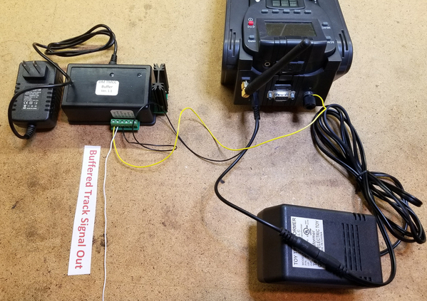
DM TMCC Buffer Connections To Command Base & Track

Attachments

Images (1)
  • mceclip0
Last edited by gunrunnerjohn
Original Post

Replies sorted oldest to newest

This track signal booster sounds good, I would be very interested in more information on how this works. Back in 2007 or 2008 Dale was at my home and we hooked up some sort of electrical apparatus on my layout, I think it was something to do with TMCC operation.  I have this unit on a shelf in my train room. Either way, Dale and I spent some quality time together as I gave him a tour of fine layouts in Tn., Ky., and Ohio.  He was a fine person, and very intelligent. Thank you Gunnrunner for continuing his work. 

John,

Thank you for picking up this topic!  Having not needed a booster in my small space with the TMCC controller I bought from you last year, I never responded as a Beta tester.  I did just buy a Legacy 990 a couple weeks ago, and got my first engine programmed without incident, so I just want to follow along.

"Dale's Legacy" sounds like a great name for the project!!  

leapinlarry posted:

This track signal booster sounds good, I would be very interested in more information on how this works. Back in 2007 or 2008 Dale was at my home and we hooked up some sort of electrical apparatus on my layout, I think it was something to do with TMCC operation. 

That was way before Dale worked on the TMCC buffer, so I don't know what that device was. 

The TMCC booster is designed to help large layouts that have a lot of capacitive coupling to earth ground.  That high capacitance kills the amplitude of the TMCC carrier signal and causes signal reception issues.  The buffer is a very low impedance 3:1 amplifier that can drive a lot more capacitance and still keep a reasonable signal amplitude.  I think Dale started on this one sometime in 2015.

Last edited by gunrunnerjohn

Thank you for responding, and I admit, I am not great at electronics. I am adding a picture of the Manco product I have. Maybe you can tell me what it's designed for. I was having signal issues around 2000 thru 2005 and Dale and I talked a lot. My situation was totally corrected with earth ground wiring. The new Legacy equipped engines run so great, no signal issues. Thanks fir this thread.IMG_8886

Attachments

Images (1)
  • IMG_8886
leapinlarry posted:

Thank you for responding, and I admit, I am not great at electronics. I am adding a picture of the Manco product I have. Maybe you can tell me what it's designed for. I was having signal issues around 2000 thru 2005 and Dale and I talked a lot. My situation was totally corrected with earth ground wiring. The new Legacy equipped engines run so great, no signal issues. Thanks fir this thread.IMG_8886

That is the booster for the output of the serial port (DB 9 connector on the Legacy Base) as it pertains to running multiple TPCs and some Z Stuff drivers. It has been "replaced" by Lionel with the SER2 module used with LCS and provides a higher power output from the serial port.

Add Reply

Post

OGR Publishing, Inc., 1310 Eastside Centre Ct, Suite 6, Mountain Home, AR 72653
800-980-OGRR (6477)
www.ogaugerr.com

×
×
×
×
Link copied to your clipboard.
×
×