
Here's another success story for Dale and John's buffer.  I run TMCC only on a very large layout with about 2400 feet of track.  I've added earth ground wires wherever needed so the layout typically runs very well.  In order to test the unit, I disconnected an earth ground above a track in a tunnel (where there are 2 overhead tracks).  A diesel with marginal antenna would run through the tunnel with headlight blinking wildly and would sometimes stop in the tunnel.

With the buffer up and running, both blue LED and green LED lit, that same diesel runs through the tunnel smoothly at any speed with an absolutely rock solid headlight.  No flicker at all.

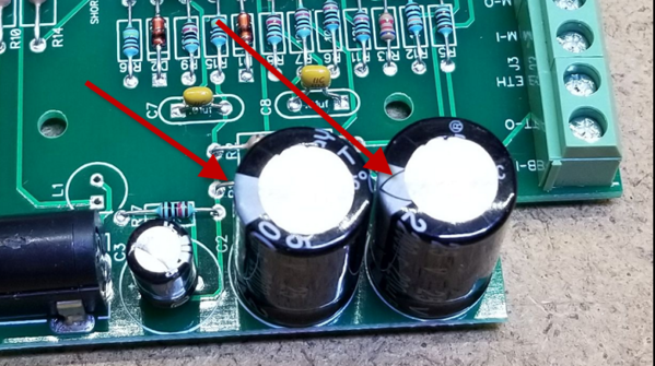
My DC voltage measurements are 2.75 volts at the Base terminal and 3.86 volts at the Boost terminal.

Good stuff!

Last edited by Bob
Rayin"S" posted:

John, Just got my booster hooked up to the layout, I have been away for a while, so I don't know if this has been brought up before. I have a two rail layout and with the booster hooked up I have both the green LED and the red LED lit. Is this an unusual happening? Tried operating for a short time and things seem ok but I am wondering if this tells of a problem.

Ray

Green and red?  Are you sure you're not talking about the blue power LED?

What are you using to drive it, the original TMCC command base, or a Legacy command base?  The older TMCC command base doesn't put enough signal out to get the green signal indication.  If you're using the Legacy command base, it's not putting out a full amplitude signal.

John, I am using a Cab 1l system, I attached a pictures howing both red and green illuminated.

Ray

Attachments

Images (1)
  • _IGP4519

Ray, that is a good picture, it is exactly what mine first looked like. My advice is if the layout is working, ignore it. I still have some unexplained signal issues on my 2 rail layout but fortunately found a temporary fix that by all logic should not have any effect. My current thought is one of the AS-AR-AC boards is "defective." I am not sure if you have any of these on your layout. My illogical temporary fix is to keep track power on the Turntable pit rails which are fed through one of the AS-AR-AC boards. If I do this one thing the layout works perfectly, otherwise I have signal issues even with a solid green light on the Buffer.

Ray, if you will be at S Fest we could meet up.

Tom, As far as I know, I don't have any of those boards on the layout. I ran the locomotives that had problems for a longer period today, the problem surfaced when running as a consist. The two areas that were troublesum showed no problems now. S Fest, at this time I am not sure if I can make it but will keep this in mind.

Ray

I received my legacy control base back from Lionel today. It now has a bright green light 2.001 volts to buffer and 6.37 volts to track. everything works great. The only problem is my engine roster is gone  and the base is unnamed. I can view the list on my cell phone WiFi when not linked to base is there any way to restore roster to base?

Jprails posted:

I received my legacy control base back from Lionel today. It now has a bright green light 2.001 volts to buffer and 6.37 volts to track. everything works great. The only problem is my engine roster is gone  and the base is unnamed. I can view the list on my cell phone WiFi when not linked to base is there any way to restore roster to base?

Yes, but only if you had backed it up first.  I do this via the Windows Legacy System Utility.  If you're not familiar with this, I think you may have to enter things again from scratch.

DM TMCC Buffer kits are now available.  I've attached the kit instructions and the buffer user's manual to this post so you can evaluate your need and your ability to construct the kit.  Each kit contains all the materials you'll need to build one buffer.  Thru-hole construction was used to make the assembly easier.  Also, the cases were prepped with the holes and slots as without the drilling fixture, that would have been more time consuming.

DM TMCC Buffer Kit Documentation.pdf

DM TMCC Buffer Documentation.pdf

Contact me via my profile address if you want one of these kits.

Attachments

Been having problems with the two sensor tracks on my layout. Tried resetting them checking all the plugs. Everything seems OK. The only thing I changed was adding the booster. Disconnect the booster sensor tracks work. Checked the hookup wiring on the booster and they are in the right spots. Hook the booster back up and the sensor tracks stopped working.  The booster is about 16 inches from the Legacy base. Have a powermaster bridge nearby but I tried taking that out and it didn't make any difference.

Last edited by Gweedo

I cut the trace between R5 and C6, easy to do, and soldered a couple #24 wires to the edge of the chips. And then the other ends to a 1K potentiometer. I was looking in the junk for a 2K but the 1K, 1/8 inch mounting,  is adequate for a variable gain and takes up minimal space. Instead of 3.3 gain, it now varies from 3.3 down to 1.65 which is where I leave it. Modest layout, but I like having the booster and seeing the green LED since I am familiar with the broken Legacy base with the greatly reduced output.

Be cautious tack soldering the pre-tinned wires on to the edges of the chips, because too much heat will cause the chips to slide off their pads.

Last edited by cjack
cjack posted:

I cut the trace between R5 and C6, easy to do, and soldered a couple #24 wires to the edge of the chips. And then the other ends to a 1K potentiometer. I was looking in the junk for a 2K but the 1K, 1/8 inch mounting,  is adequate for a variable gain and takes up minimal space. Instead of 3.3 gain, it now varies from 3.3 down to 1.65 which is where I leave it. Modest layout, but I like having the booster and seeing the green LED since I am familiar with the broken Legacy base with the greatly reduced output.

Be cautious tack soldering the pre-tinned wires on to the edges of the chips, because too much heat will cause the chips to slide off their pads.

I like the idea of having the gain adjustment. Just a little paranoid about cutting the trace and soldering onto the chips. My hands not so steady when doing stuff like that. Think gonna try the resistors first.

Gweedo posted:

Been having problems with the two sensor tracks on my layout. Tried resetting them checking all the plugs. Everything seems OK. The only thing I changed was adding the booster. Disconnect the booster sensor tracks work. Checked the hookup wiring on the booster and they are in the right spots. Hook the booster back up and the sensor tracks stopped working.  The booster is about 16 inches from the Legacy base. Have a powermaster bridge nearby but I tried taking that out and it didn't make any difference.

The sensor track is sensitive to the TMCC signal if the signal has harmonics or high amplitude.  The TMCC signal can be too high, so keep that in mind.  If your sensor tracks stop working, your TMCC signal is definately too high!!

That's what I did John. The 1K, 1/4 inch mounting pot that I had on the top of the case. I think I posted 1/8 inch before here but that was the shaft diameter

The funny thing is I did not have a 1/8 inch shaft knob, so I went on ebay and found a brand new old stock one for $1.50 BUT the shipping was $3. I should have ordered more than one knob now that I think of it.

I see Digikey has pots for 79 cents, I think I'll get a few and try out a mod.  My idea is to just replace R5 with a 2K pot and a 1K series resistor.  That allows me to vary the gain from about 1:1 to 3:1.  This also preserves the input signal monitoring indicators.  What would be really cool is a graduated dial with the gain figures on it, but I think that's gilding the lily.

Attachments

Images (1)
  • mceclip0
SantaFeFan posted:
Gweedo posted:

Been having problems with the two sensor tracks on my layout. Tried resetting them checking all the plugs. Everything seems OK. The only thing I changed was adding the booster. Disconnect the booster sensor tracks work. Checked the hookup wiring on the booster and they are in the right spots. Hook the booster back up and the sensor tracks stopped working.  The booster is about 16 inches from the Legacy base. Have a powermaster bridge nearby but I tried taking that out and it didn't make any difference.

The sensor track is sensitive to the TMCC signal if the signal has harmonics or high amplitude.  The TMCC signal can be too high, so keep that in mind.  If your sensor tracks stop working, your TMCC signal is definately too high!!

OK thank you for info.

When my pots come in, I'm going to test a gain control mod to the buffer.  Shame we didn't think of it before they were all built!   It will be a knob on the top that will vary the gain from 1x to 3x.  Once I assure myself that nothing bad happens when I fit it, I'll offer it as a retrofit mod, you can either do it yourself or send it back and I'll add the mod.

If I could only find someone to silkscreen a nice dial with the gain calibration marked...

Last edited by gunrunnerjohn
gunrunnerjohn posted:

DM TMCC Buffer kits are now available.  I've attached the kit instructions and the buffer user's manual to this post so you can evaluate your need and your ability to construct the kit.  Each kit contains all the materials you'll need to build one buffer.  Thru-hole construction was used to make the assembly easier.  Also, the cases were prepped with the holes and slots as without the drilling fixture, that would have been more time consuming.

DM TMCC Buffer Kit Documentation.pdf

DM TMCC Buffer Documentation.pdf

Contact me via my profile address if you want one of these kits.

TMCC Booster Kit


Nice kit. Good pictures and choice of components. Easy to build. 1 hour or so.
Thanks,

Attachments

Images (1)
  • TMCC Booster Kit
gunrunnerjohn posted:

DM TMCC Buffer kits are now available.  I've attached the kit instructions and the buffer user's manual to this post so you can evaluate your need and your ability to construct the kit.  Each kit contains all the materials you'll need to build one buffer.  Thru-hole construction was used to make the assembly easier.  Also, the cases were prepped with the holes and slots as without the drilling fixture, that would have been more time consuming.

DM TMCC Buffer Kit Documentation.pdf

DM TMCC Buffer Documentation.pdf

Contact me via my profile address if you want one of these kits.

John,

Just checking, but these are now listed as "TMCC buffer" kits - I assume these are the same as the original "TMCC/Legacy booster"  items - just in kit form ?

Probably missed the post, but are these compatible with Legacy being run through a DCS TIU/WiFi/SER 2 system ? 

Cost ?

Thanks


These are identical in function to the first run of assembled units, I didn't think I'd be able to assemble enough orders to do another SMT production run, so I just changed over to thru-hole components to make the kit version.  The circuit and function is identical to the assembled version (at least after you assemble it).

These have nothing to do with the serial data from the Legacy, and they don't affect it either.

Just finished testing the signal amplitude mode, so far, so good.  It varies the output amplitude from around 1.1:1 to 3:1 from stop to stop.   Most folks won't need this, however if you're running LCS Sensor Tracks, or you have experienced DCS issues after adding the TMCC Buffer, this mod may be the ticket to the two systems coexisting.

The installation is fairly simple, see pictures and description below.

 Remove R5 and solder pot and resistor combination across the R5 connection

TMCC Buffer Gain Mod N1

Close-up detail of pot and resistor assembly

TMCC Buffer Gain Mod N2

Drill hole(s) for amplitude adjustment pot

TMCC Buffer Gain Mod N3

Mount pot and reassemble case

TMCC Buffer Gain Mod N4

That's the installation process, so it's fairly simple to upgrade the box.

Attachments

Images (4)
  • TMCC Buffer Gain Mod N1
  • TMCC Buffer Gain Mod N2
  • TMCC Buffer Gain Mod N3
  • TMCC Buffer Gain Mod N4
Last edited by gunrunnerjohn

Hi...I know it has been a while since this topic was discussed, but, I need some help. 

When I first received John's Track Signal booster, I discovered I had an issue with my Legacy base not giving enough power (other people had this issue.)  I the legacy base back to Lionel and just got the base back which is now repaired.  

I am still getting a red light on the track signal booster.  I decided to disconnect everything and see if there a cross signal somewhere.  I did get a green light when everything was disconnected from the beginning, but notice that my DZ 2001 Data Wire Driver's red light started to glow brighter with each DZ 2500 switch machine I add to the daisy chain via the Data wire. 

I should also mention that have the driver connected to Dale's "Serial Booster", otherwise the data driver does not get enough juice from the Legacy base. 

Now, when I unplug John's track signal booster, the red light on the data driver goes out and only lights when a command is given...which is the way I think it is supposed to "behave".   

I am starting to get frustrated and am wondering if the track signal booster was a wise purchase for my layout or not.

Any advice would be greatly appreciated.

Greg

Greg, the amplitude adjustment mod may be of help here.  It allows adjustment of the gain from around 3:1 stock to around 1:1 at the low end.  This still keeps the low impedance drive but cuts the amplitude of the signal to about what the command base outputs. 

DM TMCC Buffer Gain Adjustment Modification.pdf

This may solve the issues you're seeing.  Jon Z. noted that the LCS Sensor tracks have a problem if they get too much signal, could be the DZ switch machines have the same issue.

Attachments

Last edited by gunrunnerjohn
leapinlarry posted:

I anyone reading this thread wants one of these TM Buffers, I have a brand new one Available..My Layout does not require it. See my email in my profile. It’s a great help on larger layouts.  

I was generally ok without it, but I like keeping an eye on my Legacy Base with the green LED.

Another happy owner chiming in.  I spent a little longer than Jack assembling my kit but it went extremely smoothly and worked as it should first try.  With highball signals of green and blue there was no more need for a ground plain I had previously hooked up to catenary.  I dare not comment on readings lest my novice grade talents show.  More importantly, the kit was a joy to assemble, a marked improvement on my 300 ft. layout and was worth ten times the price for anyone serious about flawless CC operation.  Best money I ever spent on the pike.  Thanks Dale and John.

Bruce

That isn't something that anyone has reported, but anything's possible.   You might consider the amplitude adjustment mod, that allows you to dial back the amplitude of the track signal while keeping the low impedance drive that helps drive high capacitance.

It's a pretty simple install, I can send you the parts for a self-install, or you can ship the buffer back to me for it to be installed.  The mod allows a gain adjustment from around 1.1:1 to the stock 3:1 amplitude.

Here's the mod in pictures.

mceclip2mceclip0mceclip1mceclip3

Attachments

Images (4)
  • mceclip1
  • mceclip2
  • mceclip3
  • mceclip0

John,   I would prefer to send to you for the mods. Would you please email me your mailing address?

Thank you

Tom, I get the static sound on both of my Berks, may be more pronounced because of the ERR Fat Boy speakers.  I put my GP7 on and can hear static in the back round, harder to pick out because of the diesel sound.  If I would not have gotten these hearing aids I, likely,  would not have heard it.

Ray

Sorry Rod, I packed two of them in a hurry and didn't stick the instructions in.  However, I can fix that right here.

Here's the kit documentation as well as the operational instructions for the finished product.

DM TMCC Buffer Kit Documentation.pdf

DM TMCC Buffer Documentation.pdf

Attachments

No I didn't buy a buffer john, I no longer can function well enough to operate the layout very well. Dale did me several favors and taught me a lot so I wanted to send a contribution to ACS along with yours. You have done a great service for OGR Members and I commend you for the hard work and time required. I will send you a check as soon as I have your Zip to go along with the address mentioned above.

Thanks

John,

I set aside a couple of hours yesterday and finally built the signal buffer kit. Haven't had time to test it over the entire layout but in preliminary  testing 3 locomotives responded well on different segments of the layout. I plan to add the pot and resistor modification and noticed the component layout is different on the kit PCB than the production unit PCB shown in the online picture of the modification. Is R5 the correct resistor to replace in the kit version PCB? Thanks for your help and all of your contribution to the Forum and to the hobby. 

All the component designations stayed the same between the SMT version and the thru-hole version, that was by design.  So, R5 is the correct resistor to remove on either version, the amplitude adjustment mod works exactly the same way for either.

All I did to do the kit version was take the SMT version and convert all the surface mount components to thru-hole.  For various reasons, the components aren't in the same locations on the PCB, but that doesn't affect what you're trying to do.

gunrunnerjohn posted:

I thought most folks liked the fact that TMCC worked all over the layout!

There is that, but I have experience with Legacy bases that have very reduced output. It's kind of like a motorcycle trip where the guy takes along one of every part that has failed before.

gunrunnerjohn posted:

This is intended to be a continuation of the original thread for the TMCC signal booster to avoid confusion. I was working with Dale to create the "production" version of the buffer.  That involved creating the PCB and building some units.  Sadly, Dale passed away before we really got started, so without his input and documentation, the project languished for some time until recently.  I enlisted the aid of another forum regular, PLCProf, to assist in recreating the schematic and getting to the point of confidence that we had a working design again.

Here's a recap of where I started after Dale's passing.

As some of you may know, I was working with Dale on this project, my end was to be creating the PCB and packaging once the design was proven.  Due to Dale's untimely passing, the project was stalled.  Since I never got to actually receive the final schematic, I did manage to round up the prototype.  I enlisted some aid in reverse engineering and testing the prototype and the project is moving forward.  We have reverse engineered the prototype and are making some tweaks.  I'm hoping to maybe have a prototype PCB at York next month, however timing may be tight, so that's only about 50/50 right now.  However, rest assured that it's coming soon.

I have what I believe is a completed schematic and I've done a board layout that should work with the enclosure I've selected.  I haven't received the boxes yet, so there could be changes, one of the delays I mentioned.  The "production" unit will have an off-the-shelf 24V power brick that is detachable.  The terminal strip you see on the side will be the "Euro" style, but my 3D library didn't have those.  Those terminals are where all the connections to the buffer are made.  The board projection with the TO-220 package will have a heatsink mounted to the two large holes and also be outside the box, this is to allow air circulation for cooling the buffer chip.  The white line on the board is where the enclosure wall will be, a slot allows the board projections. There is a power LED that projects through the top of the case, and also some signal level LED's that indicate a poor or missing base signal and also a "good" base signal.  Connections are also provided that output a DC level corresponding to the signal strength of the input base signal and the output buffered signal.

Discussions should continue in this thread.

Thank you John for your note.  Through another referall I am on your list.

The last of my parts are in, and I have commitments for a number of them.  I still have about about ten more parts sets for the buffer.  I am offering them assembled for the original price, or I also am offering a kit of parts as well.  Please contact me using my profile email address for more information.  Assembled versions will be BTO (Built To Order) as the mass produced ones are gone, and I'll be hand assembling and testing the few that are ordered.  Obviously, that will also take a bit more time as I'll be doing them on demand.

Dale will be missed. I started all of this with the first  signal booster that was built with vacuum tubes. Solved all of my signal problems. I immediately published all of the data for that device on this forum.   A few more were built by others with totally unusable TMCC railroads to solve their problems. Many people requested a solid state device instead of the vacuum tube model I was using. Converting it to solid state to make it smaller and less expensive was not something I was willing to undertake. Dale stepped in and took that task on. Thank you Dale.  I have seen the diagrams of his units and heard good things about its performance. Both I, and I am sure Dale would agree, that what we have done to solve the perplexing problem on troublesome TMCC railroads is a contribution to the hobby that we all enjoy so much and we and those carrying on the effort to make thing run smoother and better are good for all. 

Jim, you are certainly to be commended for your first version.  I know the NJ-HR used that for years until they cooked it trying to get just a little more "boost" out of it.   I am very sad that Dale wasn't around to see the logical conclusion to his efforts, he was gone way before his time!  One of the brightest guys I ever met, he had a knack for building practical solutions to vexing problems.

As users of the tube and solid-state buffers, the NJ hi-Railers are very thankful to all the contributors of these devices. With our 30' X 185' (~7,500' of track) layout, these buffers have made a tremendous improvement in the performance of TMCC!

Thanks again to all the contributors, 

Bob D 

NJ Hi-Railers

Electrical Team


If the power light doesn't come on, that's pretty basic!  Since you have a red light, you're getting power, I'd say the power LED is in backwards.

Top suspect is the output amplifier having shorts between the pins.  They are VERY close, and it's very easy to short them without knowing it happened.  Use an ohmmeter to check between adjacent pins and make sure none are shorted.

As far as the signal, lots of stuff could have affected the signal.  Do you have anything like a 'scope to look at what's happening in the circuit?

That probably didn't do it any good!   Send me an email with your address and I'll send you a replacement.  In looking at the circuit, I wouldn't expect that to cook anything else, but I could be wrong.  Actually, with the usage of that particular cap, I'm surprised it cooked, it actually has very little voltage across it in normal operation.  I'd actually expect the buffer to probably work, at least for some time, with that one in backwards.  I'd look around for any other component issues, for sure check C1 and C2 for proper orientation, they will greatly affect operation!

Specifically, note that the stripe on both of these faces the power jack.

Attachments

Images (1)
  • mceclip0
Last edited by gunrunnerjohn

Folks, I've had several kits come back to me with issues to solve, and usually it ends up that they were soldered with what appears to be acid core solder.  THAT'S A GIANT NO-NO FOR ELECTRONICS!  You must use a noncorrosive flux, the standard is rosin core solder.  I use the 63/37 Kester Rosin Core solder for my electronic work.  Save the other stuff for plumbing!

I have a couple of the final sets that I've assembled and tested on the shelf if anyone is still looking for one of these.

That would have been a good idea, but I'm winding this down now, I have a handful of parts left for a few more units and I'm done.  When I get some spare time, I assemble one or two and put them on the shelf. 

I still have to come up with a nice package of documentation so going forward after my parts run out someone could duplicate the buffer, don't want the process to get lost.

I built a lot of Heathkit devices over the years. Everything from a color TV to stereo components to test equipment. I always remember the warning that Heathkit had on the 1 st page of the assembly manual. Kits returned for repair or troubleshooting that have been assembled with acid core solder or fluxes will be returned without repair and warranties are void. Use only rosin core electronic solder.  Heathkit even went as far as including a coil of solder they wanted you to use with the kits. 

John, the gerber files and components list would be great!! 

One item we have started doing is to use a socket for the eprom for easy swap, we have 3 of the kits left, and have secreted the unit under the layout so it can not be unplugged. The units we lost to electrical overload from the ac/dc plugs being swapped lead to this change.

sandysimon posted:

I am just reading this forum for the first time - my loss at being late to the party.  Is it still possible to get one of these?  Thanks!

I still have a few sets of parts, so I can still supply them.

Ron_S posted:

One item we have started doing is to use a socket for the eprom for easy swap, we have 3 of the kits left, and have secreted the unit under the layout so it can not be unplugged. The units we lost to electrical overload from the ac/dc plugs being swapped lead to this change.

Ron, what EPROM?  There are no programmable parts in the TMCC buffer.

Folks, I have two kits left, and that's all. If someone is really wanting as assembled unit, I can build one or both of the kits, again that would cause a delay as I do them as I get time.

If there's really a lot of interest in more, I can order more parts, but it'll take some time as I need more PCB's, boxes, and power supplies, those take a few weeks.  Obviously, the Digikey parts come in a couple of days.

Gunrunner John, Question, does this kit help the Cab 1, Cab 1L, Legacy Remote, have better control of the engines at far corners of a layout? Specially if the trains in a part of the layout 15 feet away from the TMCC/Legacy bases? Sometimes my Cab 2 loses control of the engines. Just wondering if this is the fix. Thank You very much for all you do for our hobby. 

@leapinlarry posted:

Gunrunner John, Question, does this kit help the Cab 1, Cab 1L, Legacy Remote, have better control of the engines at far corners of a layout? Specially if the trains in a part of the layout 15 feet away from the TMCC/Legacy bases? Sometimes my Cab 2 loses control of the engines. Just wondering if this is the fix. Thank You very much for all you do for our hobby. 

Larry, I had a dead spot on my track that I could not overcome. It developed over a period of time. I tried everything.....I purchased this booster for John, and it was the best $$$$ I have ever spent on my layout. Well worth the investment.

Larry, I had a dead spot on my track that I could not overcome. It developed over a period of time. I tried everything.....I purchased this booster for John, and it was the best $$$$ I have ever spent on my layout. Well worth the investment.

That's the problem that the buffer addresses.  The link between the remote to the command base sounds like what Larry is asking about, the buffer won't help with that issue.  For a CAB2, I've used a hi-gain antenna on the command base, and on one instance, I actually used a 2.4ghz WiFi amplifier on the command base.  That really increased the range, and for really large layouts, it would probably be a significant help.

Hello, I have not started my layout yet, but have the design done.  Just finishing the room where it all will go.  The layout is 32' long and 13' wide.  I'm very new to all of this so I will admit I'm ignorant to all the electrical things as of now.  So, how does this all work?  Will it help me in the long runs I have? Cost?  I can send a picture of my layout if you need to evaluate my need.  I have a large collection of MTH and Legacy Lionel.  Thank you Bob  Huntnfish737@hotmail.com

I'm former North Central (1978),  then through mergers: Republic Airlines, then Northwest, then Delta. Four different uniforms in the closet. I retired off the 747-400 three years ago. I flew the 747 for almost 10 years and it was a real kick, but my most favorite in my 39 year career was the 757. Northwest only had the 757's, but after the merger with Delta got to fly the 767 also. Same type rating, and we would see a mix of both on our rotations. I think most of the 757's and 767-300's are now parked. Only the 767-400's are being used. If I could go back and fly one more trip, it would be on a 757. Unfortunately, only in my dreams....

@Jack Morey posted:

I'm former North Central (1978),  then through mergers: Republic Airlines, then Northwest, then Delta. Four different uniforms in the closet. I retired off the 747-400 three years ago. I flew the 747 for almost 10 years and it was a real kick, but my most favorite in my 39 year career was the 757. Northwest only had the 757's, but after the merger with Delta got to fly the 767 also. Same type rating, and we would see a mix of both on our rotations. I think most of the 757's and 767-300's are now parked. Only the 767-400's are being used. If I could go back and fly one more trip, it would be on a 757. Unfortunately, only in my dreams....

Did you ever operate out of Minneapolis? If you did, you very likely knew my aunt. She has been with Northwest/Delta since 1975, and will be retiring next spring.


John, quick question, finally hooked my booster and if fixed my issue of having a bad signal on a piece of track that i was using as an insulated rail.  One question, i have one of the newer ones that have a pot on it.  The printed instructions did not talk about it and i did not was to go through 19 pages here.  I am guessing it is for the signal, but how does it work?

Tony, that's a good question.  I never got around to documenting that as it was a late addition.  It does indeed vary the amplitude of the TMCC signal.  This allows you to "tune" the signal to minimize any interaction with DCS and also to reduce the amplitude if you have issues with stuff like LCS Sensor Tracks.

Even with the signal turned down to minimum, the buffer is still providing a substantial benefit, it gives the TMCC signal much lower drive impedance so that it can drive more track capacitance.  There are people that run it at the minimum with good results, it fixes their signal issue at that level.

The way to use it is simply turn it down as much as possible while still solving any TMCC signal issues, that will insure the maximum compatibility with device that may react poorly to too much TMCC signal.

@APW Trains posted:

I'm Interested in getting one for my barn layout I'm planning. 6 different levels spread across 2 storys (5000 feet of track). So I'll most definitely need one. How much do they cost though?

It will be the Cheapest and best $$$$ that you will ever spend for your layout. I think they use to cost around $100. but don't quote me on that. I have one and it took ALL of my bugs out of my layout. the best $$$ I ever spend for the Layout.

@APW Trains posted:

I'm Interested in getting one for my barn layout I'm planning. 6 different levels spread across 2 storys (5000 feet of track). So I'll most definitely need one. How much do they cost though?

Sounds like you will likely need a boost!  I suspect you'll also need to apply some of the other approaches to minimizing TMCC signal issues.  I believe that the NJ-HR has around 7,000 feet of track, and I know they don't run TMCC without a buffer.

I sent you an email to your profile address.

Last edited by gunrunnerjohn

This booster has been great for the NJ-HI Railers 30' X 180' multi level layout.  It has minimized blinking engine head lights to the point where virtually all engines run without a problem.  

While you are planning your mega layout, make sure you understand the best way to run and segregate different types of wires before you start wiring up the layout.  Wiring will make a difference on the performance of how well your engines run.

Good luck

Bob D

Sounds like you will likely need a boost!  I suspect you'll also need to apply some of the other approaches to minimizing TMCC signal issues.  I believe that the NJ-HR has around 7,000 feet of track, and I know they don't run TMCC without a buffer.

I sent you an email to your profile address.

Yup.  We have 7000 feet of track and we've been running the buffer since John put it out.  Before that we were running Jim Lefebreve's analog (tubes!) TMCC booster (which I believe was the inspiration for Dale's buffer.)   Even with that the TMCC signal can be iffy in places so we've spend a lot of time running ground wires on telephone poles ABOVE the track.  It's made a huge difference in problematic areas. Especially in tunnels as a lot of our scenery is made from wire mesh (Faraday cage!)  I emphasis  above as in the past there was a thought that a "ground plane" under the track was the way to go.  But no!   The outside rail and the diecast boiler of steamers can block this signal.  Diesel antennas tend to be on the top of the engine and steamer antennas tend to be the boiler handrails so above them by a couple of inches is the way to go.

I attached a hints and tips sheet I put together after several discussions with a Lionel electronics engineer who designed the latest Legacy engine radios.  He reviewed it and gave it his unofficial stamp of approval. We worked with him on beta testing the radios that went into the VL Bigboys and from then on.

We've used his points whenever possible and we now  have pretty reliable TMCC/Legacy operation.

While I was putting this together Bob D. from our club posted about the importance of wiring segregation.  We're talking about the same thing.

Good luck with the build and make sure you post progress pictures!

Attachments

Last edited by Chris Lord

Thanks, I have my ground under the overhead tracks.  Its just one for 3 tracks.   There is a 1/2" plywood and 1/2" foam and 1/4 inch roadbed plus the gargraves ties under the rails which is probably 1.5 to 1.75 inches to the middle track it is under.   So is that far enough not to trigger attenuation?   Is one ground wire sufficient for all 3 tracks?   I will have the signal buffer as soon as it arrives with your modifications.

Thanks,

GREG.

@Stackm746 posted:

Thanks, I have my ground under the overhead tracks.  Its just one for 3 tracks.   There is a 1/2" plywood and 1/2" foam and 1/4 inch roadbed plus the gargraves ties under the rails which is probably 1.5 to 1.75 inches to the middle track it is under.   So is that far enough not to trigger attenuation?   Is one ground wire sufficient for all 3 tracks?   I will have the signal buffer as soon as it arrives with your modifications.

Thanks,

GREG.

As John said that should be good but there's only one way to tel.  Run!

Good luck!

For a CAB2, I've used a hi-gain antenna on the command base, and on one instance, I actually used a 2.4ghz WiFi amplifier on the command base.  That really increased the range, and for really large layouts, it would probably be a significant help.

I can't believe I just lost signal (control) at 25 feet from the command base.  Yes, my body was between the remote and the base... but, it's such a dinky layout.  I did set up the LCS wifi  the other day could that have affected it?   I have a few spare high gain 2.4ghz antenna... I'll give them a go this weekend.

@Jim LeFevre posted:

You are doing better than I am. I can only get 8 feet of range on my CAB 2  and if i put my body between the base and the remote it drops to 4 feet.

Basically a totally usless device. I use my wi throttle on the iphone through JMRI and that works perfectly from anywhere.

You have an issue with either the CAB2 or the command base, that's clearly not normal operation!

I finally installed the signal booster after GunnerJ upgraded my unit with a variable strength control.    Unfortunately I still have issues.   If I turn the booster up all the way, I have no issues with Legacy/TMCC.   However my DCS units loose their horn, bell and speed control in many areas of the layout.   When I turn the signal booster down to about half way, the DCS works again but my Legacy locomotives stall in a few places where they are below other tracks.   I have attached a layout wide ground wire to the ground connection of the booster unit and run a copper wire atop the lower level, but this does not seem to work.   The areas that have issues have 2 adjacent tracks.    Might running the ground wire connection between the tracks also help?

Any other ideas on how to get both systems operational on my mainlines.

Thanks for your help.

GREG in Wisconsin.

@Stackm746 posted:

I finally installed the signal booster after GunnerJ upgraded my unit with a variable strength control.    Unfortunately I still have issues.   If I turn the booster up all the way, I have no issues with Legacy/TMCC.   However my DCS units loose their horn, bell and speed control in many areas of the layout.   When I turn the signal booster down to about half way, the DCS works again but my Legacy locomotives stall in a few places where they are below other tracks.   I have attached a layout wide ground wire to the ground connection of the booster unit and run a copper wire atop the lower level, but this does not seem to work.   The areas that have issues have 2 adjacent tracks.    Might running the ground wire connection between the tracks also help?

Any other ideas on how to get both systems operational on my mainlines.

Thanks for your help.

GREG in Wisconsin.

DCS and TMCC are not truly compatible. You can read the old post that gets into the details about this.

If you get an oscilloscope you can use this handy diagram I keep posting to help you tune this out. Basically you need to get the balance between them "just so".

just_so

This is easy on a small layout but on a large layout the signal levels vary too much from one end to the other to get a good balance everywhere at the same time. At our AGHR club we built a system with multiple feeds to the layout with closed loop phase-shifters to balance out the feed phases to avoid self-interference.... this is to solve EXACTLY your problem. It's complicated but it works. You can see that feed setup in our AGHR circuit tour. (specifically this doodle is helpful)

Attachments

Images (1)
  • just_so
Last edited by Adrian!

In addition to Adrian's comments, I'd suggest you first run the "earth ground" wires to minimize the signal strength issues, then add the buffer and tune it to the best performance.  The buffer can only address global issues, if you have local weak signal spots, it's best to minimize those before boosting the signal everywhere.  The trick is to get better balance on the signal.

Also you need to be reasonable, if you have a giant layout and 100 locomotives, but only 1 or 2 have signal issues, you may be better off looking at the locomotives themselves to see if you can add some metal and get better field coupling back to the Earth ground.

Touchups with ground wires work well (at the cost of being ugly).

Also one big thing is for the GRJ booster and legacy base itself is make sure they aren't plugged into a GFCI plug or power strip which has extra circuity in the ground for circuit interruption that 455 KHz doesn't like flowing through.  We saw some super weird stuff with a few brands of power strip.

I am using several power strips and all receptacles in the train room are GFCI. I have no problems. There is no circuitry in any power strip or GFCI the in any way inhibits anything in the GROUND signal path. The Grounded conductor and Hot conductor do go through some filters and surge devices in power strips. There are no surge devices or filters in Ground Fault devices either breakers or outlets.

You description of the problem also is not clear. Ground wire to what?  FRom where ?

Do not ground the tracks, anywhere.

The ground on the signal booster is the ground of the AC line on the power plug.  The round longer pin on the plug not the 2 parallel power conductors.
With the Signal booster unplugged use an ohm meter to check for a ground or low resistance between the outside rails of the track and the AC power ground. This should read an infinite resistance or at least very high resistance. A low resistance means that the outside rails are grounded somehow. This must be fixed. Start disconnecting everything from the track until the ground goes away. The railroad should not be grounded ANYWHERE.
I ran alot of hardware cloth ( 1/4 inch mesh screen type wire ) under all of my layout tracks on all levels as I was building the layout. All of that is grounded to the electrical system ground. That got me most of the way there but I still had problems. That is when I designed and built the first TMCC booster which was Vacuum Tube based. That solved all my problems.
The signal booster places a signal between ground ( the electrical system ground )  and the outside rails. If the outside rails are grounded then you have esentially shorted the output of the signal booster and it cannot work.
Jim

LeFevre Engineering
James L. LeFevre  P.E.

I'm talking about this grounding  impedance. With the spectrum analyzer or even just time domain scope we see with some power strips or GFCIs we develop the voltage Zs/(Zs+Zo) x V between the ground terminal on the booster and the true building ground, where Zs is the series impedance added by the strip, booster or even just inductance off a long return wire.... Zo is the output impedance of the booster itself, and V is the output voltage of the booster V = Vo cos(wt) where w is 2 x pi x 455 KHz respectively.

Since the booster has finite output impedance Zo, and finite output Voltage V, that means that to satisfy KVL that any voltage being developed in the ground path scaled by Zs/(Zs+Zo) is coming directly off your output scaled by [1-Zs/(Zs-Zo)]. It's a loop so:

V[1-Zs/(Zo+Zs)] + V [Zs/(Zo+zs)] -V = 0   (KVL!)

Some of the dollar store terminal strips did really poorly... and that makes sense... the output Zo of the booster is a low number as it should be since it's intended to drive a rather large load (lots of capacitance), so even a low series resistance in the return path can have a pretty dramatic effect on the series combination Zs/(Zs+Zo)


grounding

Attachments

Images (1)
  • grounding
Last edited by Adrian!

You are certainly correct about some of those cheap power strips. Some of the ground jumpers are just pop rivets internally. GFCI are different however. Neither in a GFCI breaker or CFCI receptacle nor an AFCI device does the ground wire go through any snesors or electronics in the device. The ground wire is ( or should be ) a totally seperate conductor and goes only to the round ground prong on the receptacle and does not even go near the device in a panel board containing a breaker. I have seen a lot of houses wired incorectly where the grounds and neutrals were interconnected in various places. This is a code violation. The building can only have one point where the grounded conductor and the earth conductor ( grounding conductor ) can be connected and that is at the service entrance panel. May larger houses have a sub panel or 2 off of the main panel and people ( and licensed electricians ) connect the ground and neutral together at the sub panels. That raise the ground above the true building ground point. It is also for the power incoming to raise the building above true ground due the the current draw for the incoming utility. Drive a ground rod into an isolated point in a yard and them measure the impedance to the main service entrance ground of the house. Can be an interesting reading in some cases. The purpose of the common ground point is at one point only in a dwelling makes the effect of a bird on a wire. If the whole building is above true ground it is not a problem since the frames of refrigertors and other things is what you could touch. BTW driving and isolated ground rod and bringing that conductor into a house without bonding it to the house main bond point is a code violation.


Jim

Thanks to all for their input so far.   First, I have a 12 gauge extension cord that goes direct to a 20 amp circuit and has an embedded 3 way 3 prong splitter on the end.    I have both the legacy base and booster plugged into the splitter.    Each has a small on off switch between their plug and the extension cord as there is no switch on the cord and the circuit plug is well under the layout with no master turnoff (mistake on my part).   I have my master ground wire in the wiring run of the power runs with the common on the the other side of the layout.   The master ground is connected to the ground receptacle of the of booster.   Please LMK if there is a better connection point.    That being said, I do have an actual earth ground in the room that goes into the house master ground if connecting to that might be a better solution.    I was told by someone that it had to be part of the actual electrical ground but I am unsure if that is correct.   Please enlighten me on that.

The areas with the problems have several parallel tracks on the lower level where the problem is as well as on the upper level.    My ground plan shield is run under the upper level on the bottom of the plywood and above the lower level.    Now the copper ground wire is run roughly in the middle which means there are 2-3 tracks on each side of the ground wire.   Not sure I need to run additional ground wires either between the upper or lower tracks or a parallel run directly over the problem areas which are on curves.   LMK.

I will look for my ohm meter and see if I can detect any ground on the tracks themselves.

Thanks for everyone's help.

So my problem is not consistent across the layout.   When I turn the signal booster up to the point where legacy has no stalls, the DCS does not work for horn, bell and overall speed control.   The DCS trouble spots tend to be on the lower level or near a cross under and never on the top levels.   This is what I would expect from legacy but not DCS.   I limit my DCS blocks to no more that 10 tracks and the 16 gauge wire runs to under 30 feet.   Yet it works fine in some areas but not in others.

Any thoughts on why that might be?   I understand Legacy is making DCS unstable but why might it different in different part of the layout for DCS?   Do I need smaller blocks or wire runs?

Thoughts on reasons and remedies are appreciated.

@Stackm746 posted:

So my problem is not consistent across the layout.   When I turn the signal booster up to the point where legacy has no stalls, the DCS does not work for horn, bell and overall speed control.   The DCS trouble spots tend to be on the lower level or near a cross under and never on the top levels.   This is what I would expect from legacy but not DCS.   I limit my DCS blocks to no more that 10 tracks and the 16 gauge wire runs to under 30 feet.   Yet it works fine in some areas but not in others.

Any thoughts on why that might be?   I understand Legacy is making DCS unstable but why might it different in different part of the layout for DCS?   Do I need smaller blocks or wire runs?

Thoughts on reasons and remedies are appreciated.

This doodle may be helpful to you. doodle

I've had a few requests for more of these, however I'm out of parts and boards.  If you are interested in one, please send me an email.  If I get enough requests, I'll see about getting another set of boards and parts and assembling one last batch.

I can say the prices may be higher, the plastic case I used has all but disappeared, and the only one I found in a search was three times the price I was paying before.  If that disappears, I would likely have to change the board form factor for a new size enclosure, that will run up to cost as well.

The same situation for the 24V power brick, prices have tripled for the same product.

Component costs have also gone up significantly in the two years since I last ordered parts for these.

Last edited by gunrunnerjohn

I can say the prices may be higher, the plastic case I used has all but disappeared, and the only one I found in a search was three times the price I was paying before.  If that disappears, I would likely have to change the board form factor for a new size enclosure, that will run up to cost as well.

John,  Do you have the dimensions for the plastic case?  It may be a candidate for 3D printing.

Well, the case outside dimensions are 103 x 64 x 40 mm and there are bolsters inside for mounting the board.  I'm sure it "could" be 3D printed, but I suspect something that size would be fairly expensive.  eBay: 255542321455 is the case I was using, but it was only a couple bucks when I bought them in quantity.  I suspect that was a huge production run a few years ago, and they were plentiful from a variety of sources.  Now that they're down to the dregs, they're pricing them way higher, $5.77 + $1.66 shipping, three times what price and shipping was when I bought them.

Add Reply

Post

OGR Publishing, Inc., 1310 Eastside Centre Ct, Suite 6, Mountain Home, AR 72653
800-980-OGRR (6477)
www.ogaugerr.com

×
×
×
×
Link copied to your clipboard.
×
×