
I am trying to get the best possible track plan/layout but i am a bit new at this. I am wanting to do O gauge but also have some scenery like mountains/tunnels etc. But i also want alot of switching while maintaing some continuous running lines. I am attaching my layout in any rail and pdf files. I am a looking for someone to help track plan but the last person i talked to wanted $2500 which is way out of my range. I just want something i can run my O gauge trains on and i plan to use gargraves track and ross switches. This was my first attempt to design something, maybe not the best design but it was a start. The files are attached. I would take help here or even a referral to someone that does track planning for a fee.  With the 10 x 11 space i have, its kinda limitied for O gauge i know but i want to get the most out of what i have and not make some bad mistakes that will cost me in the long run.

Attachments

Original Post

Replies sorted oldest to newest

I'm not going to design it for you, but offer some suggestions.  Hide the top part of your oval (either under mountains (sounds like your preference) or behind a scenic backdrop) so you can still have continuous running.  Then use the remaining portion of your layout to operate as a port on one leg of the visible "U" while using the other "U" leg as an industrial area served by the port deliveries.  The space at the bottom of the "U" could be your town area.

I would highly recommend putting your hidden area where the entrance to the center of the layout is located, and then use light styrofoam (sp?) sheets to build a removable mountain piece.  Your "port" could just be a freight yard with  pictures of port facilities on the walls.  You might even use a port "facade" so that your continuous loop trains don't run through your port operation.

Finally, be sure to use your design software with the products you plan to use.  In what you posted, you used Gargraves switches, not the Ross switches you plan to use.

Chuck

Thanks for the tips chuck that’s why i posted on here was for tips or if someone had track planning recommendations or someone who does it for a fee would also be an option since i am more of a newbie and am trying to maximize space i have with switching and scenery. The gargraves switches are being pulled out and equivalent ross switches are being added i just have not made the change yet in any rail. I would have paid one guy i talked to but when he told me $2500 i was like i’m yeah too much

@davehall83 posted:

I am trying to get the best possible track plan/layout but i am a bit new at this. I am wanting to do O gauge but also have some scenery like mountains/tunnels etc. But i also want alot of switching while maintaing some continuous running lines. I am attaching my layout in any rail and pdf files. I am a looking for someone to help track plan but the last person i talked to wanted $2500 which is way out of my range. I just want something i can run my O gauge trains on and i plan to use gargraves track and ross switches. This was my first attempt to design something, maybe not the best design but it was a start. The files are attached. I would take help here or even a referral to someone that does track planning for a fee.  With the 10 x 11 space i have, its kinda limitied for O gauge i know but i want to get the most out of what i have and not make some bad mistakes that will cost me in the long run.

Do what I do sit down with a legal pad and draw it out. I make many changes and then settle down with the idea.

Download SCARM (computer aided layout design) it's free and will give you a very good start.  A lot of folks here use it and the learning curve is not very steep.  In learning it you will learn a lot about your layout.  There is a large library in SCARM that will contain the specific track you want to use and it will give you a parts list of all the track and turnouts needed for your layout.  Time well spent!

OH!  And, WELCOME TO OGR!!!!!@!!!!!

Last edited by Dennis-LaRock

Download SCARM (computer aided layout design) it's free and will give you a very good start.  A lot of folks here use it and the learning curve is not very steep.  In learning it you will learn a lot about your layout.  There is a large library in SCARM that will contain the specific track you want to use and it will give you a parts list of all the track and turnouts needed for your layout.  Time well spent!

OH!  And, WELCOME TO OGR!!!!!@!!!!!

Very true, I like the pad first  when I am sitting outside or relaxing I can just write it down. Latter once I decide I transfer it, then it goes much smoother.

Have you looked into Ken Hoganson's book 21 Great Track Plans for Compact Layouts?  Maybe something for you to use or start with in there. I see Ken worked in AnyRail with FasTrack and Atlas O so you shouldn't have any trouble recreating his layouts. Ross and Atlas O curve turnouts are mostly drop in replacements length-wise for each other but there are some differences in curve radii so it is worth spending the time in AnyRail to fix the differences. If you plan on using sectional track I would recommend Ross over GarGraves.

Here's some food for thought.

I couldn't tell what size curves are in the FasTrack layout, but they appear to be tighter that the O-89s that are in the Ross/GarGraves version. You didn't mention what engines you plan to run and what size curves they need, but I'll assume they currently run on at least O-36.

Photo 1 is a quick (and crude) rendering of Chuck's idea to consider before you go too far drawing things on paper that simply won't fit the space or trying to use curves that also won't fit. The Blue tracks are the O-89 curves in your PDF version. The Orange tracks are O-54 curves. The Green switches and curves are O-42 with several curves cut to fit.

Photo 2 shows it separated into 2 runs with more tracks needing to be cut to fit.

As you an see, the O-89 curves will fit in either version and you can probably elevate 1 bridge over the entry, but not both. As you can also see, even using O-42 switches/curves, there isn't a lot of room for switches/spurs.

dav 2021-12-30 daz

dave 2021-12-30b daz

Attachments

Images (2)
  • dav 2021-12-30 daz
  • dave 2021-12-30b daz

well this is certainly a cool layout you have shown me here didn’t even think of it this way. I wanted to run some engines that require O-72’s like the big boy. The fast track was just for christmas and consisted of O-72 and O-36 curves all over the place but it never got 100% working right so i plan to tear that down and put up the gargraves track with ross switches. The O-89’s with gargraves were the largest circle giving me the the best possible “outer ring” so i can run some big boys or fill scale O engines that run on O-72 min radius. The big engines will only be run on the outer ring as i know i only have space for probably one of those but like you said not so much space for switching. The rest of my engines run on O-31 or O-36 like the polar express, hogwartz express and other engines i plan to buy. The more expensive engines i get will probably be in the min O-31 to O-36 minimum radius range.  But a few bigger full o scale engines i like will have to be “outer ring” only engines since they will have the minimum O-72 ring requirement but that’s something i have to live with , with the space i have unless i start making an upper and lower deck lol which may happen one day.


Mia the blue track utilizing my ross 100 and 101 switches that join the orange track? i really love this ideas and i am definitely appreciative of what you did here for me. I took a while for me to figure out anyrail but any chance you can send me these layouts so i can buy scarm and see the parts list ?

The other trick is that open bridge area is a basically a piece of plywood on a piano hinge with a latch underneath that i will have to tinker with to figure out how to get it working.

But this layout would keep me happy for the time being  and i could run 2 trains if i isolate the electrical too. The wall on the top of your drawing goes into my office and is hollow if i ever convince my wife i was going to cut 2 tunnel portals into the wall and then make it look good with some scenery and portal graphic etc then i can expand into my office and have some track there too for switching and a storage/turn table yard and maybe more running track lol.

Thanks pretty far off before i do that though. I would most likely get room in the basement for a second layout before she lets me do that one

Dave, based on this new info, I’ll clean up the design some. I’m not pushing SCARM, it’s just what I use these days. If you want to use AnyRail, I’ll post a photo with track labels and a parts list so you can convert it to AnyRail. If you just have the trial version, SCARM also has a trial version. It does things differently, so be ready for a learning curve if you try it out.

Ok, here's a version with a lot of track and switching to show different configurations. Unfortunately, the blue crossover on the left only fits using GarGraves O-42 switches, not Ross, and O-72/O-89 curves as labeled. The purple tracks are grades from 0" to 6" elevations. The clear tracks are those that had to be cut. All green switches and curves are Ross O-42. There's was no 3-way in the other photo, but I added one here to show sizing. It does limit how many spurs can be easily added, but it's something I can work on. I added the Parts List to show you that the number of pieces is under the SCARM trial limit of 100, so you can install SCARM and fiddle with the file to decide if you want to purchase it. I think AnyRail trial limit is also 100. To download the SCARM file you need to right-click and select Save As or Save Link As.

dave 2021-12-30b daz

dave 2021-12-30b2 dazdave 2021-12-30b3d daz

dave 2021-12-30b2 parts daz

Attachments

Images (4)
  • dave 2021-12-30b2 daz
  • dave 2021-12-30b3d daz
  • dave 2021-12-30b2 parts daz
  • dave 2021-12-30b daz
Files (1)

@davehall83  Dave, your layout space is similar to what I have and what @Mark Boyce has on his Blackwater Canyon layout. Check them out for ideas.

You may want to consider having a main which will handle the BIG engines (make sure you have sidings - I've found once on, I do not want the hassle of removing them) and design the rest of layout for most of the other gear which usually handles 42 inch diameter curves.  Looks like you could easily fit in several long sidings to park the long engines. 

Be careful on the grade, I do not think you have enough room to get a 6 inch rise with a reasonable grade.  For a 6 inch rise at 2.5% grade you need 20 feet of run. Stacking track on top of one another will not work at those sections. You can reduce the run needed by have one section rising and the other declining to meet in the middle, providing more flexibility in layout design. Of course that is assuming you want too be able to connect upper and lower levels.

If you want to do switching, you should look at the ideas of "a runaround track configuration" instead of dead ends in a yard.

The only thing is, was there anyway to keep ross switches in here and use the o-89 outer circle like you had earlier? I really want the reliability of those switches and the layout your showing. If we can figure that out, this would work out well. I saw the black water canyon very intersting layout that is something of interest. I may get rid of the trestle/elevated track here just to get the layout on a level working layout and do some upper levels later instead.

I cancelled my Ross order for the 101 and 100 switches so we can figure out what i need switch wise no sense of buying the wrong switches. I just really want the reliability of the switches that ross has. The elevation i am not too concerned about and that doesn’t have to be apart of the layout.  Its just that one area thats open to the floor that was in blue highlighted line which we could just run track across and use the piano hinge drop down dooor without any elevations or i can make it closed permanent as well i just have to climb under lol. The blue area is an entire piece of plywood on a piano hinge.

The gargraves switches i mean i don’t have any issues using them personally but i have no experience with them and the dz2500 switch machine. I have just heard on these forums all the horror stories of why you should avoid any other switches other than ross and people who have gotten gargraves switches have regrets and ended up tearing them out and got ross switches.

But i agree with your note saying that it’s going to reduce space for spurs because they are bigger for sure.

It would be nice to run two trains at one time by isolating electrical but that’s a secondary requirement as we gotta figure this out first lol

Just to put it out there i appreciate everyone’s input and help here. This is most certainly saving me a lot of grief and mistakes and i plan to learn from this to be able to do this on my own. I tried tinkering with the layout i had for a few hours last night and yeah i didn’t come close to the nice layout you came up with originally

If i need to keep the gargraves switch design you created because i just don’t have the space to make ross happen i will do it but my big concern was the switching derailments and reliability. For example i had another thread out here where i had a problem with my brand new polar express and this fast track. Come to find out the front wheels of the berkshire doesn’t like going into a switch unless it’s complete straight which made me have to tear up a bunch of secured fast track to put straight sections in and then it started working. I have still one section that just doesn’t work in that train but works in other trains like the wizard of oz locomotive set i have. I also watched how the lionel graduated trestle kit and girder bridge just didn’t work so well with fast track when it was suppose to and made my trains act crazy like going too fast down a steep grade and slower up in the other side of the grade and yes i expected that for sure but not as much as it did.

The topping on the issue was when i ran the N&W 612 it didn’t like fast track at all it sounded as if it were having issues with it like a small dragging noise even though this thing ran fine on the floor months ago with fast track in a basic O-36 oval with a few straight sections. The train when it got to the other side of the gutter bridge and started going down hill on an O-72 curve just fell right off the track and it wasn’t going that fast at all a picture of the locomotive i have is attached here i am not sure why it acted up maybe the turn radius wasn’t efficient for it but i know i like this locomotive and want to get it running and have a decent track with some spurs and switching

Attachments

Images (2)
  • 88A2156E-4264-440C-98F0-7825B46939B6
  • 2ED00C0E-30D6-4A8C-A352-553D25FFBFF7
Last edited by davehall83

Some engines have a lot of overhand in curves. Those 100 and 101 switches are yard switches, they are set for a 3.5" spacing and may not be the best choice for mainlines.  They could work with a straight section between two of them to space things out some more.

If you want to run larger engines on the main I would suggest using Ross #4 switches, 200 and 201 if they aren't entering a curve, otherwise the 072 or larger should be fine. The #4's don't curve like 072 but they are very close in turnout angle. Facing each other they give a 4.5" spacing. They are also the same length as the 100 switches.

Dave, ordering those 4 switches changes everything, including any idea of elevating tracks now or in the future and I’m not sure how I’m going to fit an inner loop so you can run 2 trains, much less spurs for switching. Those switches let you move larger engines off the outer loop, but then what do you expect to do with them? Granted, Ross switches are arguably better than other brand switches of the same size, but if an engine doesn’t like tighter switches, simply buying Ross switches isn’t going to solve that problem. Neither is switching from FasTrack to GarGraves going to solve your problem with elevated tracks. You said you were just going to run your larger engines on the outer loop, but buying those switches suggests you have other ideas. At any rate, I’ve gone this far, so I’ll see what I can come up with, though it won’t look anything like what I posted yesterday.

Well i didn’t really have other ideas i just picked those switches to get some switches in the loop but after playing with them it looks like they aren’t going yo help us at all. Yes i would love ross witches but if we have to settle with gargraves then that’s what we have to do. I did like what you posted yesterday very much so. I’m not saying i will get rid of elevated track for good but having a level layout may be good for starters. Let’s remove my 4 ross 101s from the equation then and 100s then see what we can do with ross switches. I like what you posted yesterday it was defiantly up my alley i also looked at scouting dads layout and it was awesome the twin pines railroad with the very first post he had. a pretty good one there i’m assuming in the same space i have or maybe i am mistaken

the larger  engines yes they will run in the outer loops which is fine with what we had there after tinkering with it i see why you had to go from O-89 on one side to O-72 there was no way to fit in those switches without doing that but i did like your outer and inner loop concept with spurs and things

Don't forget that you can actually put crossovers on curves with curved switches.  You could use either O120-O96 or O96-O72 on your curves and have the ability to run your big equipment on two mainlines, although it would obviously look better on the O120 side.  Due to your room size, though, you will probably be limited to O96-O72.

Chuck

Dave, don't pull the trigger too fast, give me a chance to see what I can some up with. These designs were all done to show possibilities since it didn't seem like you knew exactly what you wanted and I obviously didn't know you ordered the switches. Twin Pines is 9x13 and I believe the largest curves are O-72. Both of these elements make quite a bit of difference. His base elevation is 4" and the lower tracks for the overpasses descend to 1" while the uppers rise to 7" accounting for the 6" differential. That means he lowered some 3" and only raised the others 3" to get grades he could live with. I assume he designed all that BEFORE he built his bench work. You've already got tabletop bench work built, so you'd have to add layers of foam board or something to raise much of the track. I don't know what Steve's lead time is for shipping, but maybe he can hold your order a bit.

Here's some quick examples to show the difference the size curve makes. While they all fit your space, as shown in the 1st photo, note the difference they make in the length of straight sections and where switches have to be placed in the 2nd photo. Now, when you add certain switches to the mix, you limit the options even further. I added O-96 because Chuck mentioned the O-72/O-96 curved switch. When it comes to curved switches, you really have only 2 options; O-72/O-96 and O-54/O-72). I have no idea how well they operate, some users have problems, others don't. Regardless, if you want the option to move large engines that need O-72 curves between loops, you're going to have to compromise on other things. And taking large engines off/on the layout is going to get tiring real soon.

t1. T2

Attachments

Images (2)
  • t1
  • T2

@DoubleDAZ

Dont worry i cancelled the order with steve so were good to go to get this fresh start. We have all the time we need to do this right so we get something going that will work. I like having a big outer circle like the 0-96 or O-89. We can even design this with ross track and using gargraves flex if needed in places where we need flex sections. I also need to decide if i want stainless or tin rails i understand the tin you can solder wires to it which makes that a benficial factor. Your right i didn't know exactly what i wanted but the more i have seen on this post the more i start to realize what i want. So i know with that benchwork mistake i have to live with that, its sievers modular benchwork. They also have elevation studs you can buy to incorporate into the benchwork to raise the track all i have to do is pick sizes and bolt on and just get a skill saw and cut the benchwork to flex to the track. I will give you all the time you need, i appreicate you and everything your doing to help me, i owe you a case of track or something lol. If we can get ross working then we can if we cant and need to do gargraves switches then im cool with that. I found out my N&W requires min O-54 curves which makes sense why it fell off my trestle. But that could run on my outer ring and im ok with that. If i have to move the loco's and i know it gets old i will take them off and put back on if need be since my space is limitied. One day if i can go through the wall maybe ill have a storage yard and a turn table to store these guys off some spurs. I am also a bit concerned with curve switches as i have experienced with the polar express but maybe the ross stuff is good enough where they just work i havent tried them. But let ssee what you come up with but remember if we have to go back to your original idea the post with the track parts and gargraves switches we can, maybe the gargraves switches wont give me any problems which would be nice too. We dont have to do elevations either but down the road i may add that on by adding another level like you said

If we have to run the O-72 to get the right straight sections or even O-89 on one side and O-72 on the other like you did then we have to do it that way at least O-72 i think will run the big boy with a min of O-72 raidus. But if we need to do pure O-72 all the way around then thats what we have to do, otherwise i need to obtain a bigger room which i will down the road but this will at least get me into the rail roading stuff and modeling and the ability to watch my locos run, i love watching the steam thats my fav, i love loco's, i love the flashing lights, crossings , siginals i love that stuff.

Last edited by davehall83

Ok, see what you think about these. Photo 1 uses the 4 switches you ordered along with O-72 curves for the outer loop and O-42 curves/switches inside. The Gray tracks are cut tracks. Photo 2 changes the outer loop to O-89 and shows what you have to give up. Ignore the 3-way, forgot to take it out. You can elevated the right side, 2" gives a grade around 2%. You can do the same on the left, but 2" gives a grade of around 3.5%.

dave 2021-12-31 daz

dave 2021-12-31 o-89 daz

Attachments

Images (2)
  • dave 2021-12-31 daz
  • dave 2021-12-31 o-89 daz
Files (1)

@DoubleDAZ

Wow it looks like we got a winner here so both of these uses all ross switches i see the small differences compared to the gargraves but if it where you which one would you pick gargraves option or all ross? Also would you go with stainless gargraves/tinplate gargraves or ross track? I see we have O-42 for the inner track which is cool. I take it i can run just about all locos on either the O-89 or O-72 radius? The O-72 looks a bit cleaner IMO, but what are your thoughts, i like them both lol

Last edited by davehall83

You might be asking the wrong person, but I favor the O-72 version because it looks more symmetrical/cohesive and makes better use of the space. The O-89 loop is too close to being a circle for my tastes and the left side seems "off" with that open space, though it depends on what you have in mind for landscaping. I also don't like the shorter spurs. Bear in mind, I added the spurs mostly to fill the space and show possibilities.

Here are a few thoughts:
- The Red crossover tracks will let you store a large engine set to run in opposite direction while running a 2nd on the outside loop. That way you can keep 2 large engines on the layout and not have to manhandle them each time you want to run 1. You could also add 1 or more spurs to the 4 corners of the Blue loop to store even more spare engines and hide them with tunnels.
- The Orange track lets you run another engine on the inside loop.
- The Orange tracks also let you switch cars around on the Green tracks while a train is running on the outside loop.
- The Green tracks that loop around the center let you service a factory, though the spur is only long enough for maybe 1 car and the engine. It could also be used for engine storage by adding another switch to 1 of the curves.
- a train going clockwise on the Orange track would service the lower spurs by backing in.
- a train running counterclockwise on the Orange track would service the upper spurs.

tt

t

Attachments

Images (2)
  • t
  • tt

Oh, and here are the parts lists for the O-89 version and the O-72 version. You can see all switches are Ross and all tracks are GarGraves stainless with wood ties. I honestly don't know which tracks is better, but I do know the lengths of some are different, so if you want Ross, changes will need to be made. The layout won't change, but tracks aren't a straight swap.

parts 0-89parts o-72

ttt

Attachments

Images (3)
  • parts 0-89
  • parts o-72
  • ttt

Got it, this looks great, what kinda switches would be needed to add spurs off the blue loop or would it create problems with trains running across those switches? I imagine your thinking the curve section going into each corner of the table for that blue spurs. For the green spur for the factory area where you thinking adding a curve type switch to the curve? The top of the layout the upper most spur could it be extended to the left as well have it going to the right like we did on another layout you did or is it limitied by type of switch?

Overall this looks really nice. Now its just down to parts/type of track. Ross track? Gargraves stainless/tinplated? If you send me the scarm file i can open it too. How did you get the nice look in scarm that shows the blocks instead of just track lines? Its definitely an adjustment i think thats why i went with anyrail as scarm is really advanced lol

Last edited by davehall83

Admittedly I just tried an O-72 switch with the straight going out. But, you're right, going through the curve all the time might cause problems. I tried the O-72/O-96, but that has the same problem and because the curves are close doesn't really add enough space to store something large. I'm not sure the O-72 switch does either depending on how long your engines are.

Here are some different ways of adding spurs to the center Green tracks. You don't need to do both. I don't know if you plan to landscape and add accessories, just note how little empty space there is if you do all of this.

I didn't realize you installed SCARM, so here's the file.

dave 2021-12-31 daz

Attachments

Images (1)
  • dave 2021-12-31 daz
Files (1)

@DoubleDAZ

Got it at least i can delete or take all on this i really appreciate your help, if i ever bust through the wall which would be at the top of the layout perhaps on the very left side since that's where the portal would be maybe that would be an option for a curve switch or a way into the next room. I am not worried about that right now though thats like an after thought. I could also experiment with a second level in this room to get more going if i can get some type of shelving to go up above this benchwork which would be a totally separate layout wont be connected

Last edited by davehall83

@DoubleDAZ


Did you have an opinion on tin plated vs stainless gargraves and same on ross track what was your opinion ? By the way you must have alot of time outside of your railroad to help folks like me but its much appreciated, i dont know what i would have ended up with if it wasn't for everyone on this forum so much thanks to all.


I see on what you mean on the left side that would be cool.

I could be wrong, but I believe GG stainless with wood ties is what most seem to use, possibly based on price, I don’t know.

As for time, I’m retired, this stuff doesn’t take me long after years of using SCARM and I don’t have a layout at the moment. I’ve had temporary layouts, but a number of factors have kept me from building a permanent one. I may get to it next year, but it’ll only be a display layout for our collection of Bedford Falls buildings, etc. I don’t have the space for anything more than a 4x8x11 L-shaped layout. I always wanted to use ScaleTrax, I have 10 pieces of Flex, but nixed that idea when I had to downsize and the lack of availability. Atlas would be my choice because it’s quiet and looks nice, but I’m actually thinking of going old school with Menards track to support them for supporting the hobby.

Good point Steve, that’s why I said I don’t really know. 🤣 I should have also mentioned that GG and Ross libraries don’t have the same curves. They both happen to have O-42 and O-72, but they’re different lengths, so they aren’t a 1 for 1 swap. I have seen more lately who have chosen Ross track, presumably so everything looks the same. I once visited a layout in Texas that used virtually every brand and it was all weathered, so it wasn’t that noticeable.

Ross and Atlas use 22.5 degree curve sections, or 16 sections per circle. GG uses 30 degree sections, or 12 sections per circle. GG 054 and smaller use 45 degree sections. If you buy curve sections from Ross or Atlas they will all be uniform, GG will vary. Many people need the uniformity and buy Ross or Atlas. Still others use GG flex track and bend whatever curves they need. This is also pretty cost effective.

Atlas O is nickel/silver with plastic ties so it can be used outdoors. I would think stainless steel GG is for outdoors as well but not with wood ties.

I have about 150' of Atlas and close to the same amount of GG tin plate flex track down with another 200' left to go. Cost and availability led me away from Atlas. Atlas, Ross, and GG all mate up well together.

@DoubleDAZ

Yeah i guess i shouldn’t complain about my space then , seems like we all have wants and ambitions but need a warehouse size building to get it but this will keep me busy for a while for sure. I have also heard of some folks who prefer the solid atlas tracks because the rails aren’t hollow there just so many choices but your choice for supporting menards that’s definitely honorable for sure i hope you get a layout you well deserve especially since you design everyone else’s but your own but i can see it being fun when you know the software and have done it so much

@turkey_hollow_rr


Yeah i see what you mean on the track. Thing is people praise the solid rails on atlas over hollow rails on others. But then people love the looks of the ross and more uniformity and all and some like the wood look of gargraves. But the stainless i was wondering if it’s better for keeping rails clean and tidy but there is the soldering thing that was brought up but i plan to run the pigtails that gargraves made on pins but i hear a solder is more durable and less problematic which i can agree. But stainless may add durability or better looks it’s slot of choices and they are all nice looking tracks

Dave, I have designed no less than 10 layouts for myself, but something has always come up before the build starts. Then we decide something else is a priority, so the available space and location change. I’m not a railroader, so I just want to watch some trains go through Bedford Falls when we eventually get it set up. It’ll basically be a temporary Christmas layout that will stay up year round.

I think Atlas is the better track, but it gets pricey compared to others. The solid rail is why it’s quieter than the others, it also seems to stay clean longer. I’m originally from Wisconsin, hence my loyalty to Menards. I had planned on Atlas until the design got pared down. One thing I’ve heard about GG is there’s quite a bit of variance from track to track, like 1 rail being slightly longer than the others, so you need to take your time assembling it. Just don’t expect to lay a track, tack it in place, lay the next ones and everything will match up perfectly, dry fitting is best. Cutting the curved tracks take particular care because if they’re not cut at 90°, the straight spurs might not end up straight.

I actually lIke designing. I did programming in my former life and using SCARM takes a lot of the same skills as writing a program. A lot of modelers enjoy building more than operating trains, I enjoy designing, or at least helping when I can.

@DoubleDAZ

Wow i know indian head very well i grew up in waldorf, md over 28 years living there and indian head is a frequent visit when i lived there. Woodstock isn't too far away either. Do you come this way often? I see your in IL. The river is definitely the nice part , i live close to the river which is nice just not too close to be in a flood zone lol, kayaks are definitely fun not to mention the mountains are really nice and trains as well. By the way how do i get the print and digital subscriber/support on my banner i paid for digital and print o gauge railroading magazine but it didn't update my profile.

Last edited by davehall83
@davehall83 posted:

...By the way how do i get the print and digital subscriber/support on my banner i paid for digital and print o gauge railroading magazine but it didn't update my profile.

Sometimes it takes a day or so for your subscription to be updated so that your profile has the Digital Subscriber tag added along with the ability to view the included OGR videos.  I'm sure it will get sorted soon, but since this is a holiday, maybe by this Monday at the latest.  If this isn't resolved by then, you could contact Alan @OGR CEO-PUBLISHER

I think it is all good track each with their good and not so good points. Atlas may be a little quieter, but I also think some of that is perceived because what I do hear is lower in frequency because of the solid rails. That's what I hear in my smallish room. What one might hear in a large club layout may be different. Road bed makes a big difference also.

This is GG tin plate flex on the left, Atlas O on the right, coming off of a Ross switch.

tracks

Attachments

Images (1)
  • tracks

@turkey_hollow_rr

Thanks for that i just have to decide now what i want stainless or not the soldering thing is a good point i just dont know what advanatage stainless has. I also have to consider ross track too because turnouts are black plastic and wood phantom track is not but i like the wood phantom track too lol.


@SteveH

Thanks for the help there, i sent him a note because it was created on december 27th i think the issue is i didn't use the forum link to purchase the digital archives/supporting member. I went directly to the o gauge rr magazine website and bought it there, i got an account id and all that but it never updated my account here probably a mix up unless that is different than the subscription offered here and if it is, i will gladly pay the $12 to support this forum, this is quite frankly one of the best forums i have ever been on there are lots of good people here and its very encouraging.

Not sure where you saw IL, I’m in Peoria AZ (Phoenix). My first visit to Indian Head was in 1993 when I retired from the Air Force. My friend, Arlo Bowie, also grew up in Waldorf and La Plata. Our next visit was in 2009 when I retired from the post office. We’ve probably visited half a dozen times since and I’ve been to DC 10 or so times. My friend passed away in June 2020, so we’re going to try to visit his wife again in 2022, but that’s subject to how worried she is about covid.

@DoubleDAZ

Sorry i meant AZ, if your ever in the neighborhood let me know we can always talk trains lol. I am also very sorry for your loss and hopefully your friend is doing ok despite the covid and all the craziness in the world right now. I just wish it would go away to tell you the truth so we can all go back to normal lives.

Air Force is my favorite every time i think of them i think of all the air shows and blue angels i used to watch when i was a kid it was neat and still is.

I was going to ask maybe i already did but what should i lay cork under the track? If so whats a good brand of cork theres so much out there. I know midwest had one that gargraves sells as theirs.

@turkey_hollow_rr

What kinda road bed do you have in the picture there it looks good! All these tracks seem to have a good point to them and they all look good, can i just have them all lol.

My story here so everyone knows my dad when i was growing up setup my very first train table when i was about 6 in the 1988 era and we ran HO scale. He used a 4x8 plywood with some legs on it and green grass covering that they sell at hobby shops and away we went. We had just the basic dog bone circle and maybe 2 switches it was atlas track and we nailed it down with finishing nails and had some RR crossings and buildings but i always loved playing with the switches on the switching part of it and also loved RR crossings, the lights and all that and i always wanted to do more and i would get out those big atlas catalogs from the hobby shop and just dream of the bigger layouts and more switches. I never did get to expand on it. I visited my grandfathers home town about 2 years ago in Altoona, PA horse shoe curve and visiting the horse shoe curve was the best thing i ever did it sparked my model railroading memories and then i started collecting items from shows like the greenberg train show and other shows that are in MD. Ever since i have been a fanatic. I really love the bigger engines on O gauge and i love the HO scenery so its always been a hard choice between which one but i fell in love with these toy trains and everything i have seen at the shows so i just had to build my own layout and here i am

@DoubleDAZ

Would you mind doing a version 2 of the most recent layout with using ross track and switches and i guess gargraves flex where needed to create custom sections, i am having a heck of a time trying to cut the flex in any rail (i know you use scarm) without getting errors that my radius is too small or it just doesnt look right see screen shot. I am recreating the drawing in any rail just so i can try it out on this software since i know it. It looks like in scarm you ended up cutting one of the gargraves o-72's to fit that inner circle section to get it straight. At least thats what i think you did. I didn't know you could cut the regular track, if you can maybe i can cut the gargraves O-72.


flexcut

Attachments

Images (1)
  • flexcut

Happy New Year!

The road bed is Ross under the switches. All the rest is Flexxbed from Hobby Innovations. Good stuff. Not necessarily cheap and a little different experience to order but I'm happy with it.

I don't know SCARM but I can help with AnyRail. Here is how I make curves with flex track. I'm using GG but this works with atlas flex in AnyRail also.

Highlight and right click on a piece of flex track. Select "Curve flex".

flex_track

You'll get a window for entering the angle and radius of the curve you want. I'm using 22.5 degrees and radius of 36".

curve

This will create a curved piece already sized to length.

curve_track

Cutting is just as easy. Put your cursor where you want to make the cut and right click for the menu. Select "Cut flex here".

cut_here

Now you have two pieces of track at the length and radius you want.

pieces

Attachments

Images (5)
  • flex_track
  • curve
  • curve_track
  • cut_here
  • pieces
Last edited by turkey_hollow_rr

Dave, I can convert the design to Ross track, but I didn’t use any flex track. While it’s easy to use flex in software, I think you’ll find it difficult to bend and align flex in reality, especially short pieces like the one in your photo. You have to take special care to align the joints to avoid kinks and that’s a lot easier with longer pieces. It’s also easier to bend to O-72 than it is to O-42. O scale flex is not at all like HO scale flex, I’ve played with ScaleTrax flex (arguably the easiest to bend) and used flex on one of my HO layouts in the past

At any rate, I followed Dan’s AnyRail instructions to bend flex to 22.5°/36” and how to cut it, but that didn’t show how to fill a gap with flex. I don’t know if AnyRail lets you measure the gap and use that in place of 36” to get a perfectly sized 22.5° flex curve. I assume you cut sectional track the same way. In SCARM, you add a flex track to one end of the gap, then move the cursor to the other end and right-click. The hard part is maintaining the O-72 or O-42 curve when installing real flex track on the layout. And, yes, I see the “kink” in your example and that’s the problem when laying actual track.

.

Last edited by DoubleDAZ

Dave, if the piece is flex you can disconnect it, grab the end with the cursor and drag it where you need to.  If you pull it longer than an unmodified flex length it will turn red to warn you.

All of my straight Atlas track is flex but I don't recommend it for bending curves because it is very difficult to bend even with large radii. It will constantly try to return to straight. I struggled to get a 5 degree bend with a radius close to 088. Note also that even with this small bend it was necessary to trim the rails even on one end. That's just how it works making curves with any flex track.

Most all of my curves are close to 080 and 088. I made a plywood curve template to match the radius at the inside edge of the ties. This made bending the curves much easier and avoids kinking even across joints. The GG flex is 37" so it is not too difficult to get 30 degree pieces and cut down on a few joints. People have reported bending flex around the bottom of small trash cans. No matter how you bend flex it will always need to be trimmed even. That's pretty easy with a dremel but there are many ways to do it.

I believe this is why GG sectional pieces are not uniform, they are bent in a similar manner. Most GG users are used to laying a piece, trimming it, laying the next. . .

There is also the choice to use sectional track in curves as they can also be cut to whatever you need.

I don't think AnyRail will cut sectional track.

Last edited by turkey_hollow_rr

@DoubleDAZ

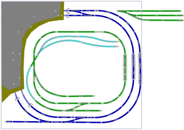
Yes please can you convert to ross track for me so i can see that version. I did what others said and that’s how i ended up putting flex in the design but your right and i rather not have to try and bend flex track. It looked like on the gargraves version you used regular sectional curves and cut them which anyrail won’t let you do it only allows it on flex track. But i much rather if your able to take sectional track and cut it, do that instead of dealing with flex. i just didn’t know you could do that, but in the drawing world scarm is the only one i found out that will let you cut sectional track so i used flex track as a “filler” to make the software happy but i made notes to just buy the sectional track pieces and cut them.

I much rather stick with ross sectional track 100% that’s my preference and not use any flex track if i can help it just less headaches as me i much rather cut a sectional piece of i had to choose a piece o had to cut.

One piece that’s not even in any rails track library is the O42X i saw you used which i didn’t even know existed and i couldn’t find it on Ross website but that sure makes things easier if he has transitions like that.

I guess this is telling me i need to learn scarm and use it and don’t look back lol.

One question had and it looks like ross track is all tinplated steel is that the same tinplated as gargraves tinplate or is it a bit different material ?

I believe ross switches are also tinplate steel or are they all steel?

I was assuming at first the ross track was more of a plastic wood tie because of the black color but their web site says they use real wood ties. I was like well if i had to buy for say a bumper or just a piece of gargraves track does the phantom wood or phantom plastic match the ross better?

Also i do have a bunch of gargraves track pins, their #4 screws, pigtail wires that go between the track pins and all that mess do you think that will work with ross track? I see ross track when you buy it you can ask for sectional wires to be added to each piece for $4.95 but is that the same thing it’s just a pin that slides in one of the rails with a pigtail that hangs down?

I wonder what ross wants you to do to secure their track to a permanent layout like is it the same as gargraves where you drill a 1/8 hole in the wood tie and use an #4 pan head screw


The other part is i would definitely like to use ross bed because it looks easier to lay than regular cork with the track grooves in there.

@turkey_hollow_rr

Happy New year to everyone here!

Thats exactly what i did in anyrail which works fine with flex but i can’t cut sectional track like scarm. I wish they wills add some things scarm could do because any rail is easy to use but most folks like scarm i noticed so i may be having to switch to that if i need to cut sectional curves and straights. I got a dermal 4400 for christmas as well as gyro wheels for gargraves that should do it for cutting and also got the dremel reinforced wheels as well

Last edited by davehall83

I believe this is why GG sectional pieces are not uniform, they are bent in a similar manner. Most GG users are used to laying a piece, trimming it, laying the next. . .

There is also the choice to use sectional track in curves as they can also be cut to whatever you need.

I don't think AnyRail will cut sectional track.

That is what the folks at GarGraves told me. Trouble is folks tend to think they can just lay GG tracks and things will match the software, they’re used to FasTrack just snapping together.

I played around with your instructions and figured out what Dave was doing wrong. All he needed to do with his short piece of flex is select it, then right-click and select the “Smooth flex” option. And you’re right, I also don’t see an option to cut sectional track, so gaps need to be filled with flex.

BTW, is there any way to change the dimensions from cm to inches? I didn’t see one.
EDIT: I found it.

Last edited by DoubleDAZ

@DoubleDAZ

You can still do the design in scarm i’m fine with that. I was just trying it out last night and i did do the smooth flex option but i still had a very nasty curve joint lol. I rather use 100% ross and cut sectionals trust me i see what your saying i bought a few pieces of flex to see how it worked and i said to myself you know if i can get away cutting sectional track that would be ideal lol

Its under the settings area i believe in measurements you can change from cm to in

Last edited by davehall83

Dave, I found the cm to inches setting.

I also retried the smooth flex option and saw what you meant. I think the difference is I lined things up using an O-42 curve, so the flex was replacing a section of O42 curve and it came out smooth. I offset the switch a tiny bit and got the same result you did.

I also don’t see the O42x in the AnyRail library, but both SCARM and RR-Track list is separately. I don’t see it or the O42p on the Ross order sheet. Maybe they come with the O-42 switch like the makeup curves for some FasTrack switches. FWIW, the O42 switch design serves a dual purpose. Adding the O42x gives you a complete O-42 curve while adding the O42p gives you a parallel spur. That’s not the case with the other switches.

I have no idea about the pigtails, type of track or how to secure them.

If you’re comfortable with AnyRail, I wouldn’t switch just because of the O42x. I would check with Steve to see if it’s actually sold separator cones with the switch.

t

Attachments

Images (1)
  • t
Last edited by DoubleDAZ

davehall83, I think you would be very happy with Ross sectional track. Many consider Ross switches as the best you can buy. Those other 042 pieces don't exist but you can cut them from 042 curves as you lay the track. Those are 45 degrees so you should be able to get two pieces to do what DoubleDAZ designed. In software you can fill these in with flex if you really need to.

Yes, use the #4 screws. You can buy them from Ross or from McMaster-Carr.

I don't have any experience with the Ross wire drops. For Ross and GG I flip the piece over and solder wires directly to the rails. One drop covers 12 feet or more of track. I solder directly to the Atlas track clips, much like the ones they sell, because it is difficult to solder to solid rails without melting the plastic ties.

@turkey_hollow_rr

I see i thought maybe the O45X was a piece that they sold but now that makes sense just cut it but i have a question out to steve at ross to see if they come in the O42 turnouts like doubledaz suggested they possibly may come as a package thing to help complete that curve.

Its nice that it covers at least 12 feet of track but if i wanted to be really careful to ensure no voltage drops maybe every 6 feet or is that over kill?

When you solder the wires are you doing it on the side of the rails at the bottom of the rail? Thats my worry too is i got a good weller and it has plenty of tips just wasn't sure if i risk melting the track ties.

Does anyone have a suggested transformer to use i have a CW-80 and a GW-180 (but may sell the GW-180). I was thinking a ZW-L at some point or the MTH equivalent i just want something nice and that has plenty of power to push multiple locos especially if i isolate track.

Dave, assuming Dan is correct, I went ahead and cut replacements for the O42x and O42p tracks. I left the originals in (clear tracks), just moved them out of the way. One thing to note is that the track center rails are about 3" from the edges, so you need to check the clearance needed for the engines you plan to run. The design can be shrunk 8", the length of the Orange straight track on the left side. If it needs to be shrunk, the spurs will have to be shortened a bit.

dave 2022-01-01 daz

dave 2022-01-01parts daz

Attachments

Images (2)
  • dave 2022-01-01 daz
  • dave 2022-01-01parts daz
Files (1)
Last edited by DoubleDAZ

@DoubleDAZ

Thanks again for doing this so track center rails are about 3" from the edges, your saying the orange line on the right side is the 3" issue? Do you think i will have issues with a big boy or something like that running? I think if i am looking at this right the potential 3" issue track is the right side where they go over the opening? What made the center of the rails different i guess thats something new for me to understand   Just want to make sure i do this as trouble free as possible

Even if Ross doesn't offer it as a package with the s 042 switch I wouldn't be surprised if he cut a curve sectional to what you want if you asked him.

Sure 6 - 8 feet between drops is fairly common. Voltage drops are going to be determined more by distance from the transformer and wire size.

I use a Weller, around 675 degrees with a 3/32 wide tip. I tin the wire and bottom of a rail, then solder the wire to the rail. This helps cut down on the time the heat is applied. Other than getting in between them, the wooden ties shouldn't be a problem. I don't use flux but I do scuff the rail a tiny bit with the dremel, especially the center rail.

@turkey_hollow_rr

Once steve gets back to me if the answer is no on the O45X and P's then i will ask if he minds cutting me some save me some time lol. I am running 14 gauge copper wire for all my power drops. I do home runs to a break out panel that has the + and - Side with screw terminals. Then it has a bus bar connection for the + and - off the transformer.

I wanted to use 14 gauge to alleviate any issues with voltage drops and have a good solid connection and i totally believe in solder. I have this weller kit i just purchased just for my train hobby and i always need a good solder gun when i want one i never seem to have one so i got a good one.

Weller WE1010EDU Soldering Education Kit, Multicolor, 8-piece kit

https://www.amazon.com/gp/prod...00?ie=UTF8&psc=1

What percentage or type of solder is good for this 60/40?

@DoubleDAZ @turkey_hollow_rr

Got a response from steve on that O42X and P this is what he said basically its cut my own.


No its easily cut to any length with the dremel

You add the P to any section of track and we will solder the clips to it

I asked him about cutting one for me and this his statement

Probably cant cut it to the exact length you want. Your drawing you will find is an approximation and everything most likely will not fit without some adjustments

@davehall83 posted:

@DoubleDAZ

Thanks again for doing this so track center rails are about 3" from the edges, your saying the orange line on the right side is the 3" issue? Do you think i will have issues with a big boy or something like that running? I think if i am looking at this right the potential 3" issue track is the right side where they go over the opening? What made the center of the rails different i guess thats something new for me to understand   Just want to make sure i do this as trouble free as possible

No, I'm saying the short Orange track (red circle) on the left between the 2 switches is only 8" long, so you can only shrink the layout that much. I took 8" out of all 4 sides and the photo on the right shows those changes. I'm not suggesting you do that, I'm just saying that the maximum because once the 2 switches join, you can cut any more.

The little Yellow box at the top of the photo on the left is 3" deep showing the distance from the center track to the wall. We tend to measure from center track to center track when discussing track separation. Dan mentioned the spacing for the 11° and #4 switches as being 3.5" and 4.5" respectively. The 3" I'm talking about is not exactly the same because it's to a wall, not to another track, so it's actually equivalent to 4" or so. The general rules of thumb is 3.5" separate in yards and 4.5" on mainlines. However, when curves are involved that may need to increase because of the overhang of the cowcatcher and the midsection of long cars, like passenger cars. Unfortunately, there is no standard for cowcatchers and the amount of overhang depends on the curve, the tighter the curve, the more overhang. It also depends on the specific engine because there is more that one version of a Big Boy. The only way to know is to lay some tracks and place the engine on them to measure the maximum overhang through the curve. If you know the specific engine, someone might be able to tell you how much there is with O-72 curves. Some modelers play it safe and use a separation of 6" or more because they don't know what equipment they'll buy in the future.

tt

Attachments

Images (1)
  • tt

@DoubleDAZ

Got it that makes sense so the good thing is i have 2 to 4 inches from the edge of the blue line to the wall so the table isn’t exactly but up against the wall so that will help with that. Thanks again now i think i’m ready to start building and buying track lol! now the fun begins but this will evolve slowly as i’m sure there probably is at least $2500 in track between switches , road bed and sectional track but the good thing is i can do the outer circle first get those switches in place then keep going and test as i go

Last edited by davehall83
@davehall83 posted:

@DoubleDAZ @turkey_hollow_rr

Got a response from steve on that O42X and P this is what he said basically its cut my own.


No its easily cut to any length with the dremel

You add the P to any section of track and we will solder the clips to it

I asked him about cutting one for me and this his statement

Probably cant cut it to the exact length you want. Your drawing you will find is an approximation and everything most likely will not fit without some adjustments

He probably didn't understand that the only reason it's an approximation in the drawing is because he no longer offers those tracks, so we substituted cut tracks. He may not have the dimensions he used when he did offer them, but they were both standard pieces at the time. SCARM says they're 4.76"/11.73" respectively while RR-Track says 4.62"/11.38", maybe they're both using different rails for the measurement. He's right though that you have to cut carefully or the tracks connected to it will not be straight.

Here's an example. for the design. The lower cut is correct and the connected track is straight. The upper cut is off by just a bit even though it looked right, but you can see the connected track is not straight. Now, if you lay that switch, then the cut track and subsequent straights, they are not going to connect where they need to. That's why it's important to lay sectional track and dry fit things before cutting, especially curves.

ttt

Attachments

Images (1)
  • ttt

@DoubleDAZ

Yeah i get that for sure now, thanks for pointing that out. I was just thinking how easy it could be to throw off an entire circle or layout just by once piece not being cut right so laying it out and pushing the sectional together maybe the best bet then cut the pieces last, the other thing is im sure this is common but when i did it on fast track its always that last piece that completes a circle that i have to bend twist and curse at to get it to go together and sometimes i get worried im going to bend it too much or put too much force im going to break it or get it out of alignment i like to do things carefully and right so i guess im in for the learning curve on this but the dremel with the gyro cutoff wheel will be my friend on the O42's, i have learned so much just on this forum alone its amazing like the fact that i can cut sectional track and put pins in it to connect it was something i didn't know i could do that changes everything. I thought you could only do that with flex but now i know its done made a world of a difference and it would be much easier IMO to cut something thats already curved to the radius i need

FWIW, I found that it was far easier to achieve the results I was looking for by using flex track for much of my track.

As for uniformity between Gargraves & Ross, I personally don't think there's so much difference that I need to sweat it.

Ross switch on the left, Gargraves FLEX on the right.  Both are tin plated rails with wooden ties.  Some of my Gargraves has ties much closer to the Ross shade, other pieces are lighter like this one.  This is older track, probably why it's lighter.

Attachments

Images (1)
  • mceclip0

@gunrunnerjohn

Thanks for putting that up there for me to see that, thats exactly what i needed to see and realize. I am definately going all Ross on this layout but if i ever had to use some ross flex at least i know how close they look as far as color and all that and after doing some ballasting and things im sure it just blends in. I have read some of your other threads on gaps like that with the track, i used to be real worried about any gaps but realized after reading things on here as to why the pin stops are there and why its good to have a small little gap for thermal expansion/moisture differences in the winter/summer that it needs room to expand and contract. Also you get that neat clickity clack i believe as well which thats something i want to hear. After doubledaz and turkey_hollow_rr and other folks on here did some comparisons on track and noticing the differences they all seem to have something unique and cool about one over another but the good thing is between the brands cant go wrong and even atlas i have considered but settled on ross as my final decision since from the postings and what i have seen atlas switches are hard to get especially with supply chain shortages im sure. But i know for sure i will be happy with this and if it wasn't for all that have contributed to this forum i wouldn't have made some expensive mistakes. Its one thing to make a mistake and learn from it and correct it, but another when you put out hundreds of dollars on things and have to trash it all and buy it all again thats what i dont want to do because then i look at it as well i could have used that money to buy a nice locomotive, more track , scenary, a building or something lol. But i know sometimes you will have mistakes that cost but if i can avoid them awesome. My goal is here to learn from everyone, i am learning scarm and anyrail at the same time but i think im going to convert to scarm the biggest thing is for cutting straight sections thats a big deal for me now and also i notice alot of folks prefer it and i like it too just a bit harder to use. Once i learn and become efficient at this , my contribution is to also help someone else just like me in these forums where i was at today so others can enjoy this hobby so right now i may be taking help but at some point i will be offering help as well so this forum can continue to thrive and get more people involved into model railroading. I also want to see younger people getting involved more too because i think that the "computer age" while it has helped us alot, it also is taking away from the hey lets get out a board game or family time or run some trains and build together as a family so your involved with others and not isolated to a phone or ipad. I am trying to push this concept in my home now so my kids can learn to appreciate this hobby and others. I think its healthy to take a step back from the digital age and do things like this. I want the generational hand down to keep going with this hobby so that it just doesn't get put on a back burner for an ipad or computer theres just so many things to appreciate about this hobby.

Here's a better shot of some the newer Gargraves and the end of a Ross switch.  The colors are a bit closer.  The gaps you see here are because that line between the sections is a power lift bridge, to that track on the right comes up over two feet to allow me to walk under to the inside of the layout.

Truthfully, unless you're really looking for it, a couple feet away you usually don't even notice the color variations.

Attachments

Images (1)
  • mceclip0

@gunrunnerjohn

Ah you just peaked my interest here with that power lift bridge, so i have a use case right now on my layout where i have a fold down piano hinge piece of plywood with a latch on the right side of my layout which allows me into the space. I plan to have straight track across there but i have the issue where i need to figure out how to have a drop down piece of track that goes back into place once the plywood is latched back into its normal position. I have been doing research and looking at all the different ideas but the one thing that stumbles me is ok how far away or how close to but the tracks together on each side so i can let the plywood drop down and go back into place without breaking anything and not having too much of a gap that it derails something. Its also on my big outside loop and inside loop which means theres no way around it unless i decide to make it a fixed plywood door or something and just duck under

@DoubleDAZ

Well i just purchased scarm so now i have both anyrail and scarm to play with, i actually am starting to like scarm more i mean i like it all but at least i have choices now to use to model things im going to play around with it and i see alot of youtube video tutorials out there on how to do things im going to start watching some videos and training myself on this so i know it more. One thing i been wondering if your doing any elevations in scarm and you get the 2.5% grades and all that like we looked at before, not that i am going to do that for this layout but i just wondering how do you take the elevations from the scarm drawing you do IE translate it from paper to the benchwork? Thats one thing i think i should learn at some point is how to take whats on paper for elevations and make them. Like where to start, how tall of a piece of plywood/board do i need and how much bigger does each board need to be as it elevates etc to achieve the grade that its suppose to be and all that stuff

Also i noticed my paypal said that its milen is the owner of scarm its amazing you even know that person to influence scarm updates/changes thats actually kinda cool!

Last edited by davehall83

Milen actually beta tested the early versions of his software by giving it away on this and other foras.  He still maintains a thread on this forum to announce product updates and new features.  For what you are building, you probably could have used the current free version (limited to 100 pieces of track), but I'm always happy to see a model railroad vendor get rewarded for his work.

You mentioned that there is some room between your table edge and surrounding wall.  While that may eliminate any scraping or gouging caused by larger engines, it raises another issue to consider.  If one of your big engines derails at a point where there is too little table space to "catch" it, it will go to the floor and may be severely damaged.  Such a fall will not be covered by your homeowner's insurance, so leave a good 4 or 5 inches of space outside your outer most loop in an effort to minimize the likelihood of such an accident.  The other alternative is to attach a raised lip, probably about 2 or 3 inches up, all around your table to protect your equipment from such a fall.

Chuck

The trick to a flip up is to have the hinge above the rail, obviously, a flip down needs the hinge below. I shoot for the width of a saw blade for track cuts along seams.

I believe John has a Mianne lift.  I built a DIY version.

lift_table

I also overlap the table a bit, hopefully scenery will help hide the seams some more. If you look close here, these are different cuts of Atlas "placed" next to GG flex on the top route and atlas next to another Ross switch.

table edges

Attachments

Images (2)
  • lift_table
  • table edges

@gunrunnerjohn


Wow yeah so i wanted mianne benchwork as my first choice but the guy never responded to me or was very sporadic he wouldn’t return calls and then he would reply to emails then when i got him on the phone he would say yeah i’ll have it to you tomorrow my bench work plan but every few days i called i got the same story i think he’s overwhelmed with work but his product is solid and i wanted his benchwork but since he never replied o ended up with sievers which it’s very good as well maybe i can find that power lift section on his website to order

Dave, there are all kinds of techniques for building grades. You’ve used the trestle sets, but they’re designed for grades around 5%. Woodland Scenics sells readymade 2%, 3% and 4% foam Incline Kits than can be shimmed for other grades. Google “cookie cutter benchwork” and you’ll get examples of all kinds of methods used.

@DoubleDAZ

Thanks for the tip, so far with the layout the track total in materials is around $2525 which is about where i thought it would be thats just estimating the track only on ross's website and i will probably order some extra pieces in case i make a mistake, break one all that good stuff. I will check out the cookie cutter stuff see what i can find, now that i have seen scarm and purchased it i am having fun with it, i actually prefer it over anyrail i been playing around with it and see why scarm is preferred and it does things anyrail just doesn't do

Last edited by davehall83

Dave,

Dan's photo is an excellent example. It shows both tabletop decking and open framing with cookie cutter sub-roadbed on risers. He has attached his risers to the top of the framing using pocket holes and some of the riser are notched at the bottom with part sitting on the decking and part on the framing. You already have a full tabletop, so your risers would sit on the tabletop just like the trestle set supports you had with the FasTrack. Instead of the track sitting directly on the supports though, you'd add sub-roadbed like Dan's and the risers would support that. I don't show it, but on top of the plywood sub-roadbed would be whatever roadbed you choose (cork, foam, Ross, etc.) and then the track.

ttt

Here's a closeup the support. Note the 3% angle on the topper.

t

3D view.

tt

Here are the heights at the track joints. They can be used to guesstimate how many risers you need and where to place them. Since folks tend to build framing with 16" centers, placing risers every 16" or so seems reasonable, but that depends on the thickness of the sub-roadbed and the weight of the engines you plan to run. One thing to think about is the easements going into and coming out of the rise. You don't want to immediately go from 0" to a 3% rise with your first support. Here, too, the length and degree of easement depends on the engines you run and how far out the cowcatcher sticks. If you rise or drop too quickly, the cowcatcher will hit the rails.

tttt

Just a 3D view with a 3" rise over the entry. A 3" rise gives you a 3.1% grade.

ttttt

Attachments

Dave DoubleDAZ I should have explained that the little 1/2" pieces on some of the risers were added when I decide to make the upper level 10" instead of 9".  I added 1/2 on some risers and extended the transition to level on the upper level to get the additional inch. Not that the risers can't be built that way.

One thing to keep in mind when going from software to reality with grades is that in software all of the measurements are relative to the top of the rail. That is the zero reference and it is really 1 7/16" higher than the framing in my case. (Plywood, homasote, roadbed and track.) You just have to remember when you go up X inches there is some structure below that, but the height dimension in software will still give the proper cuts. If the software said that point in the curve needs to be at 7", that's what I cut the riser to. If there is plywood and homasote on the framing below that point I have to compensate for that to keep the reference correct. This case is a little easier since all of the surface is in place. You just need to account for roadbed and track. I don't see any overhead crossings in Dave's design but if there ever are it is really important to understand this so you have enough overhead clearance.

Dan, got it. That explains why it looks like there's a notch in some of the risers. Good points about the clearance. In this case, there are no overpasses, but I did put together a version where I swapped the Blue and Orange tracks on the right side to create 2 overpasses. Since Dave already has a full tabletop and rigid foam sheets come in 1" and 2" thickness, I raised the whole layout 4", then added a 3.5" downgrade to the Orange loop and a 3.5" upgrade to the Blue loop, a total of 7". Those result in grades of 3.7%, not ideal, but doable with modern engines.

tttttt

ttttttt

Attachments

Images (2)
  • tttttt
  • ttttttt

@DoubleDAZ  Nice update to the track plan.

I understood Dave to want to run large engines so he needed 072 for at least one loop. Right now it looks to me like he has no place to park an engine and cars. His room should have space for a narrow dead end "shelf" which could come off the upper track to the right of the entry keyhole - which I think is a solid wall.

All - regarding the risers - I've taken this approach on my layout and even went to the extent that I precut my risers with the slope on one end and flat on the other. I only did this because I did not know any better and I already had a plywood deck in place. This worked fine for the install, but as time went on I needed to make changes and the (cheap) 1/2 ply I used warped in places. (Supports were 12 to 16 on center and it still warped screwed down.)  This made making adjustments really hard, one because I had already installed hardscape and two I had no access from below.  When I do this again, I would use Wescott's method of attaching risers to the bench work and not a plywood deck. But given what Dave is trying to do, the approach suggested will work fine, provided he puts in enough large holes (hand sized)  in the deck for wiring of track, switches and other goodies. Cutting holes in my underlying plywood deck has created nothing but headaches as the vibration causes all kinds of things to loosen and move around.  Adding switches or signals later is not fun.

As far as the transitions to a new grade, I found cutting a section of plywood long enough to to start the transition and get into the grade was critical for smooth operation. (Wescott uses the cookie-cutter term for this.)  The plywood is going to have to bend into an "s" shape - which it will not want to do. However for our purposes that is a good thing. 

Okay Jeff,  you have gotten my curiosity up. How are you going to bend plywood into an S curve?

Enjoy reading this discussion. We are all Ross and use RRTrax which has been accurate to within 1/4” and is usually dead-on. As someone suggested earlier, after measuring carefully and going thru the gyrations, we found that dry fitting and winging it works pretty good. As you gain experience, it gets fairly easy.

Ross doesn’t make flex track. Steve sell Gargraves, track screws, cork, etc and has been great to work with. We are on level 2 and have installed 40+ Ross turnouts. If you are going to have a large number, you might want to do the soldering yourself if you are good at soldering and save the $$$.

Good luck.

@ScoutingDad posted:

@DoubleDAZ  Nice update to the track plan.

I understood Dave to want to run large engines so he needed 072 for at least one loop. Right now it looks to me like he has no place to park an engine and cars. His room should have space for a narrow dead end "shelf" which could come off the upper track to the right of the entry keyhole - which I think is a solid wall.


Dad, if you look back a couple of days (post #34?), you'll see I posted a photo with a switch in the upper right corner going to the right. I couldn't tell from the photos that have been posted what was to the right of the layout, so I ended the spur at the end of the table.

However, there are problems with adding a switch to any of the corners. Dave doesn't like the idea of running large engines through the curved part of switches, and I agree with him as a general rule. However, I'm not sure how big a deal that is with O-72 switches at reasonable speeds.

In any event, Dave then he goes on the suggest a future expansion into the room on the left which would require switches in the corners. I'm not exactly sure what he has in mind, so I drew up a plan with a loop of O-72 tracks going into that room as well as a spur onto a shelf in the upper right, assuming I understood what you're suggesting. He also suggests he may want to elevate sections of Blue loop on the right and I've posted suggestions for how to do that.

So, assuming he doesn't want to add the shelf to the upper right, my "idea" for parking large engines is to park them on the Red tracks. Both are 50" in length and should hold at least 1 engine each allowing 3 large engines to remain on the layout. Rolling stock and smaller engines would be stored on the Green tracks. When he wants to run a smaller engine around the outside, the Blue track on the left would become a passing siding. He'd move the large engines to the passing siding and run the smaller engine around the Blue/Red/Orange loop. I realize that's not ideal, but little is when trying to cram so much with special requirements into a relatively small space.

Bear in mind, these are just my thoughts on how to make things work. I don't advocate any particular way to do things.

dave 2022-01-01 expand daz

Attachments

Images (1)
  • dave 2022-01-01 expand daz

@DoubleDAZ @Bill Webb I love this forum - great comments and thoughts.

Bill - the second article I started to write addressed this. However since that is not going to happen, Westcott's book on page 10 has 2 photos on how this happens/works. (no photos - copyright)  Plywood is resistant to sharp bending so for our purposes this works to our advantage. If we were going up the lower section is firmly secured to a base.  Then we start bending an upwards curve, then we insert a support and then bend the plywood back down. This forms an "s".  This is the only place where cheap 1/2 plywood works, since it bends easier. BUT - if bent too much, the transitions will be too steep and the bigger engines will not be happy. Think about when you cut a plywood sheet on sawhorses - the unsupported section will bend by itself. I'll have to measure mine, but I think I was getting about a 1/2 inch rise over 24 inches ( roughly 2% ).  I do not think you can get that degree of bend out of a 3/4 sheet, especially baltic birch type. Of course that is a good thing if you are trying to run scale wheel sets.

DDaz - I spent a few hours mulling the layout a couple of days ago.  I did not think there was really enough room for a rising section without getting too steep (for me its 2.8 max, 2% or less ideally).  Missed the extension from your earlier post, but that is what I was thinking. I also thought there was an exterior window where the blue extension is shown. I do not have any problems running any of my engines through an 072 or greater turnout. But generally I agree with staying away from designing using the turnout as normal operation. Of course then there are the ROSS curved turnouts, which for me have worked great in my tight layout.

I also agree with the comment - don't use cheap 3 ply 1/2 inch plywood. It will work for a while and then become the source of operating issues. I have learned my lesson from trying to go cheap. 

Jeff

Jeff, I don’t advocate what I show in the photo, just wanted Dave to see there are options depending on what he wants. My biggest point though was that if he were thinking about what I show, he needs to think now because now would be the time to raise the height rather than have to tear up ALL the tracks to do something like that later. I believe he mentioned putting in the switches for a potential future run into the other room and that would be smart if he’s really serious about doing that. My only concern there is I don’t know what’s on the other side and how O-72 curves would fit. I thought about the window using 2 switches with a Sri siding there instead of the switches in the corners. Here’s what that would look like.

t2

Attachments

Images (1)
  • t2
Last edited by DoubleDAZ

@DoubleDAZ

This is interesting and thanks everyone for the tips here on elevations but the hole in the wall scenario would be through the top of the drawing in the left corner area, the next room goes through the top wall. The left goes through my window/outside and the right goes into hallway area, its open area but not much room to spare. If you look at the fast track pictures i had earlier on the posts you will see what i mean. Below the lay out on the bottom is an open stairwell/split foyer, i could go past that railing there if i took something and built that up some how

Last edited by davehall83

This is what I was considering after I gave up on connecting track. Individual loops but different elevations.  Left corner is supposed to be a hill.  I would probably move the inner loop to give a foot or so (from what would be walls or rock face) to give space for buildings / small town and road. I thought the inner oval would be really boring, hence the turnout and 30 degree crossover into the "yard". 

Instead of the 072 turnouts, people use Ross #4s (?) for switching to different track?

Anyway just ideas to mull over and discuss, as Dave said, I am not advocating anything - Just trying to see what might work and what are not so good ideas.  This is a tight space to work with. 

Attachments

Images (1)
  • mceclip0
@ScoutingDad posted:

Instead of the 072 turnouts, people use Ross #4s (?) for switching to different track?

If you're asking the question, here's part of the reason why. Even if you aren't, others might wonder.

- With #4 and 11° switches you get closer spurs using the TR series of sectional transition tracks without cutting wide curved sectional tracks.

- See what happens with the O-42 switch since Steve deleted the O42P parallel transition track.

- Note the smoothness of the 11° and #4 turnout sections compared to the others. That allows for higher speeds and smoother operation. I believe the general rule is 11° switches for yards because speeds are slower and #4 switches for mainline spurs because trains °are still passing at speed, though I think most folks like 4.5" or more of clearance.

Of course, different brands offer different options. Atlas uses a #5 with a 1/2 O-72 and a #7.5 with a 1/3 O-81 to get even closer, but most people find they can't get their fingers between the cars to pick up them up.

switches

Attachments

Images (1)
  • switches

@Doubledaz @ScoutingDad

I definitely like the drawing you did above as well with the mountains and tunnels so now it’s a choice between more switching and spurs or more continuous running lines. I defiantly also liked doubledaz’s design we did and the one i loved was that double cross over to the left but obvious i can’t do it because it’s a window and outside but the one with the loop above is certainly an option The only issue is on the right there is a walk in closet on the left it’s just a wall so i probably could only go into the room on the car left side and if you start from that wall corner and count about 6 (6 feet from corner left wall to to right) squares without me measuring exactly i can only go that far right but the room i have 17 feet back which would essentially be if you drew a line on the far left corner and went 17 feet up that’s how long it is and it’s 10.5 ft wide. I could get some stuff out of that office and make about 70 to 80% useable if i wanted


Also i haven’t ordered anything yet and this is an interesting discussion on the #4 turnout should i consider using that type on the mainline instead of the ones we picked ?

Last edited by davehall83

As Dave said, the #4's give a smoother transition between mains but the truck movement is similar to 072 only with out the S curve.  A pair of #4's give 4" of space while the 072s give 5.5". I don't run steam so the closer spacing is not an issue for me. They are the same length as 072 so they can work in many of the same applications. If the turnout continues through a curve I tend to use curved switches, but I like the #'d switches for mains. I'm not sure if the trucks turn much at all through #6s but they're 20" long and require a lot of space. The #4 can also be used in yards as well as the 100's. You can get 3.5, 4.0, or 4.5 spacing with those TR tracks, and these also work for sidings between #4s.

Not sure how we got on the subject of #4 vs O-72 switches. The Blue ones in the design off the main as well as the Orange ones are 11° switches, not O-72 switches. They are almost identical to #4s, but would require cutting O-72 curves and a lot of other changes to fit while providing absolutely no benefit. The point of my example was to explain why folks choose certain switches in various situations, not to suggest anything in the design needs to be changed. The 11° is just what it says, 11°, while the #4 is 14° and the O-72 is 22.5°.

t

Attachments

Images (1)
  • t
Last edited by DoubleDAZ

@DoubleDAZ

Sorry about that dave, i probably didn't understand or put in perspective what you had wrote earlier. I agree no design changes but i was just curious about that switch but your right no changes. Looking at the turnouts and examples does help me understand the curves off these switches alot better so thanks for everyone putting these examples up here and also helping me out with my build, i cannot tell you how much i appreciate everyones help on here, you saved me $2500 in design fees alone, i know i owe someone a case of beer or if you dont drink beer a case of train track or something. By the way you guys are pretty fast popping up these scarm drawings lol, i know its not that hard to add track but your pretty quick. I think that open office space in the future is going to give me alot of options and the tunnel through the wall will probably look cool.

Dan, stir things up all you want, discussions are the way we learn so we can make informed decisions. I didn't use any curved switches, partly because Dave doesn't want to go through curved turnouts, though thinking about it, it wouldn't really be the same as going through the turnout on a regular switch, but it's still a switch. Another reason is that the last time I did, several folks suggested I avoid them. The main reason though is because at the time Dave had already ordered the 11° switches.

At any rate, I decided to see what it would do and here's what I found. Using the O-72/O-54 in place of the 11° means cutting more curves to end up going straight. The resulting C2C separation between the straights is then wider, meaning the Orange and Green tracks would have to be moved/shortened. Maybe I'm missing something, but I don't see an advantage.

tt

Attachments

Images (1)
  • tt
Last edited by DoubleDAZ

So now the question is, what transformer and what type of control system for this layout. TMCC, Lionel Layout Control System, DCC?

I also have seen people talk about rail sounds and things like that to get realistic effects from your trains. I know alot of loco's and diesels do this but is there any suggestions on that part , i know alot of times you want to wire things as you go because it may require a solder connection to the track or some type of sensor installed. I havent tried any of these things yet but there are so many options out there picking the right one or best one is always tricky

Chuck, that's a good example. One difference is you're using Atlas track and their 1/2 O72 curve to end up straight, nothing to cut, nothing to waste. However, since I had nothing better to do today and my wife was out, I worked up 2 new versions using curved switches and some numbered switches.

Length of Blue track went from 548.34" to 521.61" to 518.1
Length of Orange track went from 413.91" to 405.63" to 418.02"
Length of Green track went from 664.12" to 644.52" to 652.99"
Overall length of track went from 1626.38" to 1571.68" to 1589.81"
Number of cuts went from 14 to 21 to 26

Now, I don't know what to make of the numbers, if anything, and I'm sure some tweaking would change things, but I tried to keep the designs as close to the same as I could. I doubt anyone would notice the difference in sizes during operations. For me, adding the curved switch to the Blue line eliminates the capability to use the Blue turnouts as a passing siding or temporary storage for large engines.

tttttt

If this were my layout, I'd probably try a double crossover, something like this. It lets one use the Blue route as a passing siding or storage for a 2nd large train. If I wanted to add some buildings, I'd remove the Purple spurs to make room. After looking at the version with numbered switches, I'm not sure how well they'd work, but I'd try them. The one place I can see value in a curved switch is in one or both of the Orange curves coming out of the double crossover.

t2

Attachments

Images (2)
  • tttttt
  • t2

Dan, that’s a really nice configuration. I thought about making a “real” passing siding/storage track that allows smaller trains to use the whole layout unimpeded, but was concerned about reducing the inside space for the operations too much. I don’t know exactly what kind of day-to-day operations Dave plans, how much running vs how much switching to move cars around, etc., I’m not even sure he knows at this point. I’ll merge your design in SCARM and Dave can take it from there. He’s got quite a few options, all with different capabilities and costs.

Wow thanks everyone yes please do keep the recommendations going your right i don’t even know exactly what day to day operations are planned i just like watching locos run. Day to day stuff isn’t so important to me as scenery and running the trains. I am sure at some point i will start to realize what day to day things i want but don’t forget i also have that office space that shares that wall at the top of the drawing so i can also expand on the layout once i cut holes into the drywall. If you take the layout at the top left corner of the drawing and count 6 feet to the right that’s how much space i have going in and out of the office because after 6 feet it turns into a walk in closet. But that closet is very small. The room once you get past that wall is about 17 feet long by 10.5 feet wide and i can probably clean it out and use about 70 % of that space.

All these ideas are awesome and yes this is how i learn too anyone with different ideas or if you see something that can be improved let us know i welcome any and all ideas as this is how i will too learn and see differences with different drawings.

I thank everyone for their input here. Thanks @doubledaz for continuing to make the changes as ideas come up and i do open these up side by side in my double screen monitors to see the differences that’s how i relate and compare even the part drawings with the different turnouts etc it’s all very cool and i have learned quite a lot here

This most recent drawing with the double cross over does have me quite interested and i have held off in ordering anything too fast or at all just so i can see how more ideas come up i don’t want to jump too quick as i see these ideas come up i can easily change up my parts list and and go with the changes.

I may not respond as quickly but i am reading for sure only because i had to go back to my full time job after christmas break lol but i always have fri-sun off to mess with trains and even adter work


So now the question is, what transformer and what type of control system for this layout. TMCC, Lionel Layout Control System, DCC?

I also have seen people talk about rail sounds and things like that to get realistic effects from your trains. I know alot of loco's and diesels do this but is there any suggestions on that part , i know alot of times you want to wire things as you go because it may require a solder connection to the track or some type of sensor installed. I havent tried any of these things yet but there are so many options out there picking the right one or best one is always tricky

@DoubleDAZ

Thanks those are close but i’ll probably need to do an more exact measure meant fa toting in the walk in closet and areas i can’t use in that room but other than that this is close. This one’s not a immediate thing at all that’s later down the road but i will for sure get the switch setup in the main layout for it so i don’t have to rip up track later.

I have to convince the wife to let me bust the wall down lol or make the tunnel, i told her i can always get a drywall guy to redo the wall if we sell the house one day it’s not that big of a deal 😂 but you know how wives are when us train guys want more room even though it’s my office that’s getting the wall cut up 😝

Hooefully someone here had some electrical experience with the different type of TMCC, LCS and DCC options and even rail sounds so i can factor in thear ideas too.

davehall83, you want to enjoy the presence of the trains and you don't want them to become an obstacle or an eyesore. If you do decide to go through the wall try to make as few holes as you can and dress them up.

Here's a 10000' level overview.

In O we have conventional control and command control. Conventional is the original train control where the speed is controlled by increasing or decreasing the voltage with the handle of a variable transformer. There are two major players in command control, Lionel Legacy and MTH Digital Command System (DCS). Legacy is a superset of TMCC. These systems run with a constant 18 vac and all control is microprocessor based. You push a button on the remote and a message is sent to the engine.

DCS works best by following a few recommended practices during wiring. Legacy/TMCC will work fine with this and only requires a single wire connection to the common rails. You can issue TMCC commands from the MTH DCS system using a serial cable between the DCS base (TIU) and a Legacy/TMCC base. But this arrangement will not issue any advanced Legacy commands. Or you can just run the Legacy/TMCC engines from the Lionel remote.

@DoubleDAZ and folks here ,

So my layout is about to get even better so i know i said i was going to cut that office wall later but i i thought about it and i should do it now so i don’t mess up any scenery or track and things with drywall dust so that being said the attached photo of the latest layout you made me is going to happen the tunnel portals will be on that wall and i am attaching some photos of the wall and the next room the track will go into. The office space will get cleared out so don’t worry for this layout. No benchwork or anything has been done i am probably just going to get the hole cut and maybe put some tunnel portals in the wall i can get off lionel or woodland scenic or something. The guy cutting these holes for me wants to see if i can get a styrofoam tunnel or something to model against so he can cut the hole tight and make it look good with a tunnel portals. So i am open to suggestions on tunnel portals to go against the wall and also any design considerations and designs for more track into this next room. I think i do want a ross turntable and roundhouse stalls for my trains in this room along with lots of track and stuff. I realize to make this look good making the wall look like rock and a real mountain portal and tunnel will make this really cool. I have to update the layout to show my total space but as posted earlier this is a 17 long by 10.5 wide room. We can explore multiple levels and all kinds of ideas. I love where we have gotten this so far and making these decisions up front helps me avoid having to climb in the inaccessible areas to try and make the drywall cuts. I have to figure out a good way to take your track plan and get a to scale drawing or some how get it laid out or measured out right so i can ensure one i am laying track in the right places based on the drawing and secondly to make sure the tunnels are cut right in the right place. So ideas on that and tunnel portals and all that are welcome


I am attaching photos of this and latest layout dave did for me and a tunnel  portal idea i see online

Attachments

Images (7)
  • 4664B7E8-9F54-478D-8942-190CECF13A91
  • 1F73F966-3753-4841-A981-0E23E3EE46CA
  • 6F195518-CBCF-4A0A-8613-5EDA2D4B362B
  • 5B42EDDD-0B39-4BE0-8913-D7EED30F5552
  • 0BED986C-2F82-4B0F-A4B2-53BF3F2AFB78
  • 535BBE54-4E24-48C7-9661-FDE6514D1613
  • E18B91B2-B068-4999-8B9C-C4669C59D922

Well, with this development, your original layout can look a lot less cramped!!  Couple of comments, though.

Entering your wall/tunnel directly off of a switch is going to cause multiple problems.  First, switches are natural derailment causers; maybe not frequently, but even once could be a problem tearing up your tunnel or damaging your engine.  Best to enter tunnel off plain straight or curve piece of track, and don't even think about putting a switch (even partially) in a tunnel.

Second, you could put your tunnel entrances at the bottom of a wall-painted tunnel, but that will look cheesy from some angles.  You might consider using a smaller 3D mountain piece against your wall that then blends in to your "painting."

Finally, on your plan drawing, be sure to indicate the location where you access the other room.  Also, with the added space, you could convert your smaller area into a port (with a disguised double-track loop) while using your larger space to represent a city with an industrial area, yard and enginehouse.

Chuck

Some random thoughts.

I just realized I don't know where the entrance to the adjoining room is.

Anyway, here are some thoughts.

The MTH portal in the photo has an inside width of only 7.5" suggesting a center rail spacing of 3.5". I couldn't find the total width, but there's probably an inch on each side, so now we're up to 9.5" and with any kind of landscaping and/or wider spacing, I'd plan for at least a 12" space.

However, since the tunnel will be on a mainline run, I'd suggest 4.5" or more spacing. The width of the double crossover in the photo with the 4.5" spacing and roadbed is 8" in SCARM. I added this to examples 1 and 5 for spacing and to add reversing capabilities. I also added the Ross 33" turntable and an Altoona roundhouse to show how much space they need and because they are capable of handling the larger engines. Obviously all these are just example for discussion purposes. If I were doing this, I'd probably create a full-length pass-through/see-through in the wall, though that might be too ambitious, especially if the wall is load-bearing.

Photo 1 show a double crossover creating 2 reversing loops allowing all trains to go through the tunnel in either direction. The original design is in Orange, so obviously it would have to be redone.

dave 2022-01-06 daz

Photo 2 shows a simple dogbone with trains traveling in only 1 direction at a time. It also requires the original to be redone.

dave 2022-01-06a daz

Photo 3 shows a more complicated dogbone with the angled path through the tunnel.

dave 2022-01-06b daz

Photo 4 shows the design with a slightly modified original.

dave 2022-01-06c daz


dave 2022-01-06d daz

Attachments

Images (5)
  • dave 2022-01-06 daz
  • dave 2022-01-06a daz
  • dave 2022-01-06b daz
  • dave 2022-01-06c daz
  • dave 2022-01-06d daz

@DoubleDAZ

Yeha opening that wall up would be nice but the wife may stop that lol she’s willing to let me have 2 tunnels though.

I definitely want to keep the original we had a close to what we had as possible , i do like photo 1 and the last two which had less modifications to the original deign but i also like the reversing loop ideas. Does photo 1 with the changes show that blue set of track on top of the orange have it elevated and that’s why it can be there like that ?

@DoubleDAZ

I will have to get some measurements this is very close but i will work on making changes to the boundaries of the room/walls for that office and to show the window locations and entry door and items that cannot move in that room. My general contractor i use to do drywall work was here and we discussed more of this tunnel he said he could get it to go through the walk in closet which would widen the circle but i have to decide if thats going to give me much benefit and i have a server closet in there and penetrating that wall could cause other issues. I thought about cutting some of that wall like it was mentioned to make it one wide entry / exit way for the train but i think im going to be stuck with tunnel portals. That wall we dont believe is load bearing at all. Are the advantages of using the wye instead of the double cross over better or what if we still just used one entry track and exist track like shown on other photos with the pictures you had shown just was curious of the advantages over this? Also im sure we can fill alot of this space with spurs/more track and things but a reversing loop does seem adventacious as well and i thought about this and maybe trains running in both directions are cool but i wont push my luck  there lol theres just soo many options

Hi Dave,

Here's what I think you're up against, though I'm far from a construction expert

The Orange rectangles represent 2x4 studs on 16" centers.
The Blue rectangles show where those studs would be in the pass-through wall on 24" centers.
The difficulty is getting a tunnel through the wall while avoiding the studs.

As you can see, the right leg of the Blue Wye goes right through a 16" stud, but works great with the 24" stud.
The Purple tracks have an O-72 switch with a straight track going through the wall. I think you can see that neither configuration works with 16" studs while the top Purple tracks "might" work with 24" studs.
The Yellow tracks have an O-72 switch with O-72 curves and it works better than the others, the reason I used it in my very first example. Unfortunately, given the use of a curve going into the tunnel, an extra large portal will be needed to contended with the large engine overhang Chuck mentioned. I favor a build-your-own portal, but all options will present a landscaping challenge.

dave 2022-01-06g daz

t

Attachments

Images (2)
  • dave 2022-01-06g daz
  • t
Files (1)

If I'm understanding correctly the wall in question is not a load bearing wall, so cutting the studs to allow for a tunnel pass through, would be a simple matter for a carpenter to install horizontal blocking above and below the cut studs, extending left and right to adjacent studs.  These horizontal blocks are often referred to as non-load bearing headers.  This would likely require a little drywall patching.

Last edited by SteveH

That would be my thought too, Steve. Either way, I’d cut the opening extra wide and cover it with landscaping, at least on the left side, so a portal could be installed at an angle to the wall and perpendicular to the track.

Obviously, I favor the version with the Wye because I like being able to reverse trains. It’s also a lot cheaper than the version with the double crossover, those aren’t cheap. And again, none of these are meant to be final designs.

If you want to make a straight line that's not part of the "bench", go to the left-hand column's drop down menu and select Figures.  You can then draw a very thin rectangle.

To make it a specific length, use the numbers in the lower left corner of the main window as a guide.  If it's not to your liking at first, it can be edited by selecting it again and dragging the small squares at the corners of the selected object.

If you want it to be any other angle than vertical or horizontal, after drawing the "line" select it and right-click the selected rectangle/line and choose Rotate from the local pop-up menu.

Last edited by SteveH

Yes,

Step 1 - go to Settings - Edit - Tolerances: Distance 0.06 in.

Step 2 -  use the polygon figure to draw the irregular boundaries of the room using the X - Y co-ordinates as a guide.  The co-ordinates can be found in the lower left pane of the main SCARM window.

To make the corners as accurate as I wanted, I first drew the shape getting each point close to where I wanted it.  After the basic room outline/polygon was a closed object, I then selected the polygon and zoomed in to each point and one by one moved each point to the precise location using the Co-ordinates in the lower left pane as my guide for placement.

V6b

Attachments

Images (1)
  • V6b
Last edited by SteveH

Steve, have you ever used RR-Track? When it comes to drawing figures, it puts SCARM to shame. To me, that is the biggest failure of SCARM. Now, to be fair, SCARM isn’t designed to create figures, I consider that a welcome bonus. What bugs me most is I can create the baseboard by entering specific coordinates, but not rectangles, polygons, etc. There’s probably a technical reason, but I don’t know what it is. Editing figures by aligning numerous data points is very tedious and still not “exact” because 2 points can’t occupy the exact same point. And, a true figure generator would not force one to stack tiny rectangles to create a facsimile of a slanted rail on a bridge, etc., in 3D. The other thing is that RR-Track uses “active” layers, so that if you have polygon of the room, you can make it “inactive” so it doesn’t accidentally get selected. The only way to do that in SCARM is to completely hide that layer. That’s probably why users tend to design rooms, etc, using rectangles as walls outside the baseboard. It’s the same with using polygons to get the landscaping to remain flat. In a small design it’s not that bad, but in a large design, it’s too easy to click on the poly instead of a track. Turning layers on/off works, but it’s certainly not optimum. That’s not really a critism, just an observation.

@DoubleDAZ No I haven't tried RR Track, I'm happy enough with SCARM.  Agreed SCARM is not great at polygons or other things one might normally do in a typical CAD program, but it's passable for my model RR planning needs.  I also have the room outline for my layout on it's own Layer for the very reasons you mentioned.  For the baseboard, it is IMO much easier to to enter the co-ordinates using the toolbox commands.  It would be great if that same type of data entry were possible with figures.  As far as the non-overlapping points, I've worked around that by just offsetting them by some tiny fraction of an inch, which when zoomed out doesn't seem to matter (at least to me in this application).  In the physical world of model railroading, I can deal with a 1/64" discrepancy.

I still really like SCARM for track planning, but for more critical work than a room outline, I prefer other purpose designed CAD programs.

Last edited by SteveH

Dave, I didn't get the impression you were disparaging SCARM at all, just wishing the typical CAD stuff were easier, like me and others.  Sorry I didn't make that clear.

You do so much here on the forum to help others using SCARM, I figured you like it too, otherwise you'd typically use something else.  I understood that you were just having a conversation with me and I appreciate this.  Happy to discuss, anytime.

Maybe we could ask scarm if they could add a feature they could sell to get more cad capabilities for advanced drawings or if they cold do an extension that we could buy because if they did i’m their first customer. I do really like scarm too so it’s just a matter of some tweaks they could do.

Any thoughts on the new drawing with the wall layer with my dimensions?

AFAIK, SCARM is Milen Peev, Author and Developer; one man.  He's done a lot essentially by himself to make continual improvements to the program for the purpose it's designed to do, design a model train layout.  I can appreciate that adding the desired functionality of typical CAD stuff would be a major time consuming detour from his main objective of continuing to develop a powerful low cost modelling app.  Maybe a plug-in would be possible, but even such a collaboration with another developer would mean a significant amount of time making everything compatible.  But who knows, we're at version 1.9.0 now.  Maybe it's in the works for 2.X.

You fellows are making good progress with later editions of the track plan showing a Wye and turntable.  The Wye will allow reversing trains and the TT will provide the ultimate in activity and joy of operation.

The turntable does not have to be expensive as a $10 homemade turntable is easy to build plus a lot of fun.  Here is a photo of mine, which can be built to any length.  It can be belt driven with a hand crank like mine or can have an old battery driven screw driver as power and the TT can be located anywhere.

Train Lots 5-10-2016 272

Details on construction on OGR post below.

It was great to see this track plan evolve with input from many and the result will be much greater than originally conceived.  My layout started simply 44 years ago and still improved as late as 2 years ago when I added a Wye.

https://ogrforum.ogaugerr.com/...3#157406523846615753

Scroll up the first post of this topic to start learning about the Homemade $10 turntable

Charlie

Last edited by Choo Choo Charlie

@DoubleDAZ @SteveH

Just want to make sure you guys saw this one and i am adding the picture of it too for those who dont have scarm.


Ok so i did my best here, i took one of the latest drawings and i measured every wall in the office and train room to get exact figures. Its 99% accurate. So if you look at the walls layer that is what i have the walls under. Red Rectangles are Walls, Black Rectangles are the studs in that wall so we can see what we have i did my best to get the centers and they are 16 inches to each center. The 2 green rectanges in the train room represents the gap/space of the benchwork to the wall so in the rear its 3 3/16 inch of space between the edge of plywood and the back wall. The wall to the office is another green rectangle that is 7/8 inch of gap. The train table does go down a small bit past the wall which is fine we had to create some gaps. Yellow rectangle in the back wall is just to show the one wall's approximate thickness of 4.5 inches which is what building code says it should be but dont quote me on that its just what i think it is. The office area i captured the distances of that closet. The reason why the lines are lined up the way they are around all walls is to be as accurate as possible as to how i measured. I measured on the inside of all rooms to get the inside dimensions which is usable space. The purple rectangle is the doorway into the office and closet. Also there is a desk area that cant be used that space inside the green area is an area we cant build into.

Did my best on this so we can build around the obstacles. By the way i like the revsing loop and the turn table on the left side of the room as you can see why now. Multiple levels may come into play down the road but just trying to get this one figured out. Also i dont have an issue with non load bearing wall headers and having my guy cut the studs and box them off to make the track fit properly and get the best out of this. If thats the case i just need to figure out what to stuff in that wall to make it look good and keep it framed out/looking like scenary. If you can build around these walls what were working on this will make it easier to layout. At this point with the accuracy needed on this i wonder how to use a plotter or something to get this laid out on the bench to put ontop and lay the track out right. Benchwork in office doesn't exist yet but it willl once we figure it out Scarm drawing attached. Again much thanks to all


I also agree with doubledaz here scarm is great but the effort involved doing simple lines was crazy if it were autocad this would be easier to get down to a 1/16 of an inch and get precise lines to what i measured now it’s almost exact but without snap to grid and all that stuff it’s hard and even making my lines all the same thickness which is because of the lack of a line tool. For example i feel that other programs have feature scarm doesn’t like anyrail has a line tool that snaps to grid and it’s much easier to use. But anyrail lacks the ability to cut sectional track which made this layout a complete mess on that software and i want the track to be accurate to what we are doing so that’s where scarm seems to shine. I haven’t used RR-Track but that probably had its own pros and cons too. Would be great if scarm added some cad capabilities i would be willing to pay more for an add in extension to get the abilities of drawing precise walls with lines and stuff.

I did reach out to anyrail and they said in Any Rail 7 their next release coming out there are going to be a bunch of improvements and one of them is to be able to cut section straight and section curve track like in scarm which is a big deal. That means anyrail may have an advantage with its ability to draw lines like on cad

I think that we mayu end up removing one of those 16 on center studs in that wall to get the track we want through there or tunnel, if thats the best bet @DoubleDAZ we can draw it that way and just put headers there.

Attachments

Images (1)
  • dave 2022-01-06f_walls_dh
Files (1)
Last edited by davehall83

Steve, I just didn't want anyone reading this ti get the wrong impression.

Dave, here's a photo of the file I downloaded from your latest post. Just FYI:
- I don't see any Green rectangles in the Train Room, but I get that the layout is 3 3/16" from the back wall.
- There are 2 Green rectangles in the Office, but I think I understand that there is a 7/8" gap between the table/desk in that room and the top Green rectangle and that the table extends a bit past the Green side wall.
- I understand the Yellow rectangle. The width of the wall is 3 1/2" for the studs and the 1/2" drywall on both sides making it 4 1/2".
- I see the doors and the office area that is off limits.

dave 2022-01-06f_walls_dh

With that in mind, here's my latest versions. Both versions are in the same file, just on difference layers; Alt-L and Alt-R. As you can see, O-72 curves are going to be a close fit on the right in the Office area. This photo shows the TT/RH on the left and I always fill empty space with tracks to show possibilities. No matter how you do things, the problem is going to be your ability to reach tracks that are over 36" away. The Yellow rectangles are access panels and still don't allow access unless you place one where the end spurs are.

dave 2022-01-08b daz

Here's another version, but it also needs some access hatches. I added yard tracks to both because in mu mind it's crazy to have a turntable without storage for cars.

dave 2022-01-08b1 daz

Attachments

Images (2)
  • dave 2022-01-08b daz
  • dave 2022-01-08b1 daz
Files (1)

@DoubleDAZ

Thanks for this, your drawing does align good for the office space. Now that i think about it that door for the closet makes it so that space is not usable. If we did something crazy like let the trains through the closet would that add any benefit? I do see your point with access hatches. This turntable idea does eat some space for sure. I like it but doesn't leave much for scenery or buildings i am sure. There is the area to the left of it but i guess thats cant be used because of the curves needed but noticing your ALT L it does take advbantage of that space which maybe benefical but we loose our spurs. Itas almost like that closet would be nice if a train could come through the red side of the wall next to the door. Space seems to go quickly no matter how much room you gain or loose. Will it give a parts list based on layers selected or will it just spit them all out?

I am leaning to the ALT R design. Needless to say my wife is going to think im nuts. I think the greatest challenge is going to be getting benchwork/access panels in place unless something is designed just around where the tracks need to be a bit more open type of benchwork instead of what i did in the other room

@SteveH

Hmm thats a good idea for lift bridges., maybe the Alt L is better than and just add some idustry stuff with spurs. I think on both layouts im going with coal and logging stuff. Maybe some others not sure lol. I do plan to add some coupling/uncloupling tracks that also have the operating track built in for dumping coal/logs its the gargraves pieces that have that option i think is the only way i can get that feature. Can you tell me what the two green tracks do there is 2 entries into the turn table does that allow turning around, maybe im just not seeing it or realizing the advantage to that just curious what the idea on that was.

Last edited by davehall83
@davehall83 posted:

@SteveH

Hmm thats a good idea for lift bridges., maybe the Alt L is better than and just add some idustry stuff with spurs. I think on both layouts im going with coal and logging stuff. Maybe some others not sure lol. I do plan to add some coupling/uncloupling tracks that also have the operating track built in for dumping coal/logs its the gargraves pieces that have that option i think is the only way i can get that feature. Can you tell me what the two green tracks do there is 2 entries into the turn table does that allow turning around, maybe im just not seeing it or realizing the advantage to that just curious what the idea on that was.

Thank you, bridges definitely add another dynamic and dimension to a layout.

Otherwise, these are @DoubleDAZ's designs, so I'd prefer he answer your track question.  All I did was to show how altering the bench configuration would possibly allow walk in for reaching the back corners and converted the existing bench top track to bridges.  My guess for the two green tracks would be to allow passing near the turntable, among other possibilities.

Last edited by SteveH

Steve,
Like I said, I filled the space with spurs. I thought about modifying the baseboard to add the aisle and should have gone ahead with that version too. Maybe I'm trying to make this too prototypical by thinking there needs to be a yard as well as 2 leads to the turntable. I used the largest Ross turntable, so that could be scaled down as well. Dave won't be able to turn large engines with a smaller turntable, but he could use the Wye for those.

Dave/Steve,
When it comes to CAD capabilities, it's not really a big deal because the room itself is only useful when someone is trying to figure out what will fit, like we are at the moment. I just got used to being able to enter exact measurements in RRT to get accurate figures, but things don't really need to be that exact. Once the space that will be available for the layout is finalized, the room dimensions are moot. And, truth be told, all we really need to know is the distance between the top wall and the office wall. And since the bench work is not attached to the walls, we need to know how big the gap needs to be.

Dave,
The current room drawing suggests 79" on the right in the Office room and SCARM shows the diameter of an O-72 loop is just over 75", but I don't know how accurate that is for Ross track. At any rate, if you leave a 1" gap from the wall for the bench work, the tracks will be slightly under 1" from the edge of the benchwork, but the bigger problem is engine overhang on the larger engines coming out of the curve. Mind you, the center rail will still be about 3.5" from the wall which I believe equates to a 7" center-to-center spacing and should be enough, but I hate planning a design in such a close space. I think I can safely say it won't work with a 3"+ gap along the top wall.

I'm going to see what I can do with a smaller turntable, fewer whisker tracks and an aisleway. I hope you know there isn't much room for buildings in the other room either, so if you want them, some of the spurs are going to need to b deleted.

t

Attachments

Images (1)
  • t

Dave, the 2 green leads into the turntable allow an engine to move to the turntable while another engine is being turned to leave. Otherwise it would have to sit on the mainline until a single lead track is clear. As it is, there is no place to park a train while the engine gets turned or swapped, I haven't figure out how to fit that in. With so little space, it's hard to figure out what you need vs what will fit. Ideally the turntable would be close to a yard, so the engine only has to travel a short distance to get serviced and turned. As it is, the cars will have to sit on the mainline, so you won't be able to have another train running. Again, I haven't though that far ahead until we know what will fit and where. Just because the room is long doesn't mean the space above the office is big enough for O-72 tracks.

Dave,

Off-hand I don't know of a current large engine, like the Big Boy, that will work with less than O-72 curves. MTH made a version that ran of O-31 curves back in 1996, but I don't know about others and I don't know if you'd want one because I doubt it has the details that make it impressive. However, if you are willing to keep any engine that needs O-72 in the Train Room, then we can do more with O-54 curves in the Office Room. I just don't want to tell you that  just because I think we can get O-72 curves to fit that doesn't mean some engines won't hit the wall coming out of the curves.

Anyway, here's the last version for tonight. Even switching to O-54 curves, I think this kind of configuration will be the best bet. Note that I reworked the spurs on the left to make room for some buildings and I'm not sure that will work with what you mentioned.

dave 2022-01-08c daz

Attachments

Images (1)
  • dave 2022-01-08c daz
Files (1)

@DoubleDAZ

As always thanks so much i will open the drawing in the morning. You do have a point we probably should keep the main lines O-72 so the big engines can navigate.I may do something with the green box area to possibly get that out of the way IE move my desk elsewhere or make it smaller but then again i may not gain much from that. The closet door if i made that so it was a pocket door or something similar  would that help anything ?


Your last statement you weren’t sure if it would work with what i mentioned, what did you think wouldn’t work i got lost in trying to figure out what it was we talked about

One thing i have to figure out is when i start getting a collection of train rolling stock and locos i have to figure out some type of storage for them.

What's the possibilities of multiple levels in the office and main train area if i ever want to run separate sections like different industries and no they don’t have to connect to this at all basically an upper level above this in both rooms with different layouts connected through the wall again and running separately. But lies the issues of accessing that upper level and navigating around to work on it. I have to figure that out in the main train room too. Maybe some type of customized benchwork were it’s not all covered with solid plywood maybe some open areas to navigate around. I realize in my main train room i made that mistake  

@SteveH

I just need a warehouse lol. I have to sacrifice a lot of office stuff for this extended option in the office IE less storage for my tools and stuff and i have to get rid of some stuff IE computer stuff that i work on but it’s not a lot of stuff. I will have to learn to live a very minimal lifestyle with some of the other things i do to have my trains but it’s a sacrifice i am willing to make to get my train set big enough for what i want. I have had folks tell me just run HO gauge and that will solve slot of this but i told them when i started doing O gauge and seeing how much better the Locos look and the steam and lionel stuff etc i was sold on O gauge. If i can only have one then i am going O.

Last edited by davehall83

davehall83 I only saw your topic today.  Your initial room is very close to my 11x11 room.  I opted for Ross 054 curves with 042 on sidings.  We worked on a plan early on with 072 curves, but it seemed like the layout plan was nearly circles with almost no straight track.  My outer loop could have handled it, but I don't know that the inner loop could have.  I have had doubts as I have built the layout, but am happy with it nonetheless.  I had to leave an aisle on the right side to access a sliding glass door and the entry to the rest of the basement, so the layout approaches 11x8.

Back to the Drawingboard 2021-05-03

I like where you and Dave have taken the design.  Dave also worked with me on my design.  I'll go back and read the parts of your thread I missed, since I skimmed through just now.

Attachments

Images (1)
  • Back to the Drawingboard 2021-05-03
Last edited by Mark Boyce

Dave,

The O-72 loop on the right side of the Office Room will fit, but may not be far enough from the walls/desk to allow a large engine like the Big Boy to run without hitting the wall, etc. If would help if you stood with your back to the closet door and took a picture of the opposite wall where the Green rectangles are shown in your room description.

Also, I assume there's no specific reason why the gaps are what they are in The Train Room, that just what they turned out to be when you placed the current bench work. If that is a good assumption, can they benchwork be moved closer to the top wall?

t

Attachments

Images (1)
  • t
Last edited by DoubleDAZ

Dave, you essentially have an around the room layout, just that your sides are all too deep. That's because we started with your current table in the Train Room. Here's what an around the room would look like, more or less, with a 30" reach and O-72 curves for the Blue line, O-42 for the Orange line.

test

Attachments

Images (1)
  • test

@DoubleDAZ

So i didn't answer your question earlier the train room benchwork was connected to the office benchwork i didn't know how to remove the part that was in the office that was remnants of what you had made for me in earlier drawings. The train room bench work i had put those green blocks in or gave you those measurements since we already had benchwork there and i gave you the measurements of how far the benchwork was from the wall on both the back and right side so that we knew there were some gaps there and to be more precise about going through the wall and where that wall stud and track would be. However the office protion of the blue benchwork doesn't exist and can be deleted thats just because i didn't know how to delete it without deleting the whole train room benchwork too. The office and train room the red walls are precisely measured. In the office you can go as far back to the red walls you want the blue boundary has no deciding factor on spacing. I just need to make sure we dont have a loco hit the wall lol. So I want to keep the train room the way it is as far as track and spurs i cant really change the keyhole middle design since i already have that benchwork ready and built, i was more so looking at the around the room for the office i just wasn't sure what that entailed. I think the train room with the money invested in benchwork and all it would be a real task to modify whats there and cost too, i would have done it this way had i been more thoughful with the benchwork

Also here are the pictures i will be shortening the desk to either make it the size of the green area or reduce it completely. Also don’t worry about other stuff in the room other than the desks area that can all get removed

@Mark Boyce

I really like your layout, actually your topic for your rail road some of it was one i looked at when deciding on this whole thing but i only skimmed it but it was one that others pointed out as well that was close to what i have, the only thing i have different is the expansion office where i got a bit lucky with and additional 17ft by 11ft room. My wife is eventually going to tell me my trains need a new house lol

Attachments

Images (4)
  • CC8924ED-7758-4CDC-9F92-45D8C265B6AE
  • 82E9F1A5-9211-46E4-A084-B77FD994A135
  • 9722942D-99B6-4E65-99F4-63573688D68C
  • 8C3994F0-874F-4881-AB7A-17BA40246844
Last edited by davehall83
@Mark Boyce posted:

davehall83 I only saw your topic today.  Your initial room is very close to my 11x11 room.  I opted for Ross 054 curves with 042 on sidings.  We worked on a plan early on with 072 curves, but it seemed like the layout plan was nearly circles with almost no straight track.  My outer loop could have handled it, but I don't know that the inner loop could have.  I have had doubts as I have built the layout, but am happy with it nonetheless.  I had to leave an aisle on the right side to access a sliding glass door and the entry to the rest of the basement, so the layout approaches 11x8.

Back to the Drawingboard 2021-05-03

I like where you and Dave have taken the design.  Dave also worked with me on my design.  I'll go back and read the parts of your thread I missed, since I skimmed through just now.

Mark one thing i like when i looked at your videos is how you did your elevations and tressles. How did you make them and the bridge?

Maybe i should be considering elevations in my trian room again and having multiple levels.......

@DoubleDAZ

I think dave may kill me lol if i change it up lol. He may tell me im on my own lol but i like what you done but i still like my layout dave did just the upper levels and maybe a lower level would be cool

Last edited by davehall83

@DoubleDAZ

I am pretty open to the second level and yes the left side is a safety thing i could just put a barrier up or something

Dont worry too much about that second level though that’s way down the road. You have done quite a lot for me.

I am just trying to get the most of what makes sense for the two rooms for now but i just want to make sure of any watch outs or gotchas before i start building everything so i don’t have to go rip up a bunch of stuff down the road when i want to expand to another level above or below.

Do you think the main benchwork in the train room needs to be cut back to the around the room setup ? I really like all the stuff we had on the last layout we had before we trimmed a bunch out for the train room area. It’s almost like a big give or take. You can make it more useable by having more in the space than around the room but you sacrifice that reaching distance. Right now i climb up on the train room table to lay stuff out and build but i can tell you that does stink it makes me quite sore afterwards. But that may be worth it with what i get out of the layout.

One thing i forget to mention here is my benchwork is modular so it can be moved and reworked easily. I’ll post the sections here shortly

Last edited by davehall83

@DoubleDAZ

So this is the sievers benchwork i have the bold black line sections are attached with carriage bolts and is module and can be unbolted and moved easily or removed.

Since the plywood is already sanded down and smoothed it would have to be unscrewed as it is also in sections just like the benchwork but it wold take some work and cutting to do.


Each section even the 1248 sections can be undone and moved or removed


B4383D5A-23C7-4E8C-B286-3B5D7927EDA9

Attachments

Images (1)
  • B4383D5A-23C7-4E8C-B286-3B5D7927EDA9
Last edited by davehall83

davehall83 since @DoubleDAZ survived all my changes from Plan 'A' through Plan 'D', he's up to the challenge to handle anything you throw at him.  On past layouts, I used the old cookie cutter method of cutting the plywood and putting in risers to make any grade I wanted with automatic easy transitions from horizontal to the grade.  On this layout, since the SCARM grades were near 4% and my carpentry skills are digressing, I copped out and used Woodland Scenics 4% foam risers.  The problem with them is, you have to taper into the grade at the bottom of the grade and then back out to horizontal at the top.  I had one steam engine that kept shorting out at the bottom of the grade, and front wheels would lift off the track at the top of the grade.  I did so much cutting and shimming, it would have been easier to go back to the cookie cutter I learned back in the old Kalmbach Publishing book, 'HO Railroad that Grows' that I just about wore out when I was a teenager in the late '60s and early '70s.

I was going to lift the two bridges by hand one to the right and one to the left to get into the center of the layout.  Another Forum member mike g. had a similar situation as me with two bridges to lift, one a number of inches higher than the other.  He came up with the idea of using the linear actuator to lift the lower bridge, and then have a cross brace that hits the upper bridge as the assembly goes up.  The upper bridge just rests on a 1x2 as it travels.  I covered the contact points with sticky back felt used for hanging pictures so they don't scratch walls.  So it was Mike's idea that he sent me the details, and I adapted it to my tables I had already built.  I can go back and find the details in my Blackwater Canyon Line topic if you want to go that route.

Last edited by Mark Boyce

@Mark Boyce

I am in the same boat as you i am not a very good carpenter my skills stink. The problem i may have with trying the cookie cutter is the plywood is birch sanded plywood and its the $80 per sheet expensive stuff and i heard that the 3/4 inch kind like that is hard to bend. I am not sure on that but thats what i have so i may have to do some type of risers or foam or something like you did. I did have an issue similar to you with bottom out on my fast track layout i did with the bottom of the incline not being so even or at a gradual rise. I see you used the woodland scenic stuff on your video you had and that seemed like it would work but now i know the hurdle you have it sounds like alot of work put in to get it to work and maybe i should go with another method to get a rise if i decide to do this on my layout.

Yes please on the bridge, i would like to see the actuator you used and the materials parts information so that i can too see if this will work for me. Getting the tracks close enough and the electrical and having it raise easy or lower is the biggest thing for me.

As for having doubledaz make all these changes i figured he may be up for it, i just don't like to overstay my welcome but if he is ok with it, ill keep it coming. I see your post went back for a very long time and he was with you the whole time which is cool. Were you using ross track on your layout?

Dave, there is no need to change the benchwork in the Train Room. Here's what I've been working on. If you look close, you'll see I made a few changes to the original design in the Train Room to move the left side away from the edge for safety. This version has a Ross 33" turntable with an Altoona 4-stall roundhouse with 2 extended stalls for large engines. I have similar versions for a Ross 27" turntable with the Altoona roundhouse, a Ross 27" turntable with a Korber roundhouse and a 24" Ross turntable with the Altoona roundhouse. Most of the reach is under 36", assuming I have the space available for benchwork figured right. I should mention that the 3 entryways do not need to be large bridges. They can be simple wide drop-down platforms with some sort of wall along the sides for protection.

And again, these are only ideas.

dave 2022-01-09 33a daz

Attachments

Images (1)
  • dave 2022-01-09 33a daz
Files (1)

Dave @DoubleDAZ  is right, you can just use a simple drop down platform instead of bridges.  I see from your photographs you have the basic idea already in place.  I used bridges just for a nice effect.  However, I will look into where I posted the the key points on the lift up bridges and post links to those pages.

You do have a good point about the 5/8-inch birch plywood not being as flexible as the 1/2-inch plane jane plywood I used.  The first time I did it was over 50 ears ago, and I bought the cheapest plywood available.  I have never used birch, but it is an excellent choice.  I do like the Sievers benchwork.  Very nice looking and sturdy.

@DoubleDAZ posted:

Dave, there is no need to change the benchwork in the Train Room. Here's what I've been working on. If you look close, you'll see I made a few changes to the original design in the Train Room to move the left side away from the edge for safety. This version has a Ross 33" turntable with an Altoona 4-stall roundhouse with 2 extended stalls for large engines. I have similar versions for a Ross 27" turntable with the Altoona roundhouse, a Ross 27" turntable with a Korber roundhouse and a 24" Ross turntable with the Altoona roundhouse. Most of the reach is under 36", assuming I have the space available for benchwork figured right. I should mention that the 3 entryways do not need to be large bridges. They can be simple wide drop-down platforms with some sort of wall along the sides for protection.

And again, these are only ideas.

dave 2022-01-09 33a daz

@DoubleDAZ

Ade you able to restore the original train room track back without the left having been shortened and move for  the safety space but include all other changes? I am going to design a catch on that left side that would stop a train from barreling over the side. I just don’t want to loose any of wider track radius we had or space for that. I understand the safety part so i am going to incorporate something that will allow a train at the edge not to barrel over the side

I would like  to see the drawing  with both version one where you made the changes to make it safer in the left side so make that one file and a new file with the old setup were we had the track closer to the left and incorporated the layout you made here in the office that way i can pull it up on my 60 inch monitors and compare the two layouts and decide on it but i probably will favor the one we had with it closer on the left side and just make a barrier or catch for the trains

Last edited by davehall83

As far as the clearances needed for large locomotives from the wall on O72 curves, that would be 3.25" from the track centerline for all the stuff I have and have tested.  This includes both the MTH scale Big Boy, the Lionel Vision Line Big Boy, the MTH Centipede A-A set, the MTH C&O Coal Turbine, and the Lionel scale TMCC T1 Duplex.  Those seem to be the worst offenders in my stable, all make it past an O72 curve with 3.4" of clearance to a post with about 1/8" to spare in the closest encounters.

@DoubleDAZ @gunrunnerjohn

Thanks for the inputs and redoing the drawing this looks great! I couldn't ask for more lol. The upper and lower decks come later. I do need to figure out where to keep my trains stored to keep them looking good once i start stock piling locos and stuff. I think im ready to order parts, what do you folks think? The altoona extended round house is that the one located here http://rossswitches.com/6stall...efor33turntable.aspx

Last edited by davehall83

You give me way more credit than I deserve, those are Glenn Snyder shelving, I just hung them.   From the looks of your layout plan, I'd say you have plenty of space!  I will say, if I were building it, I'd be planning on more yard space.  I started with three yard tracks all the way in the back, and I quickly realized that wasn't nearly enough!

With that realization, my freight yard extension was born, original on the left, new freight yard on the right.  I wouldn't mind having even more yard space, but that's not happening at this point.


Attachments

Images (2)
  • mceclip0
  • mceclip1

@gunrunnerjohn

Even still you made it look neat so its well deserved. Your probably right were would  i fit more yard space though lol? Im sure its right under my nose but just from observation of what has been drawn, just curious. The only thing is the wall space usually is hard to reach once you start building the benchwork without some good reach lol, i started to find that out in my train room

Is this the shelving? This is really cool idea and not that expensive https://gsds.com/

He only takes checks though, im usually Leary of writing checks

Last edited by davehall83

Dave,

Give me a chance to see if I can reduce the number of tracks that need to be cut. I put this together rather quickly and cut tracks rather than spend time fitting sectional tracks. I also want to color-code the cut tracks, so you'll know where they are. There are some very small cut tracks where tracks should connect without them when you actually lay track.

Yes and no to the roundhouse question. It is an Altoona model, but it's not the 6-stall model in your link. They make various sizes. I did this one for another client with a 34" Millhouse Rivers turntable. It took me a long time and a lot of emails to get the combination right. The client would not accept the simple footprint from their site, he wanted a something more visual and SCARM didn't have any roundhouses. He had Altoona build the roundhouse and he picked it up at York. I still don't know for sure that it fits, I need to follow up with him to see how far along he is with the build. Here's the link to the Altoona site:
https://altoonamodelworks.net/o-scale-roundhouse/

Here's a small chart showing the different combinations I played with. Note that while the Korber is the shortest, it's wider with only 3 stalls. Also note that the 33" is the longest, but it will fit, I just don't know that you really need more than the 27" with 4 stalls. I have no idea of the price difference, etc. As it is, you probably have room for 5 stalls with the 33", but then all engines are inside, unless you make the roof removable so you can have it open.

tt

Attachments

Images (1)
  • tt
Last edited by DoubleDAZ

Dave, I know you've mentioned a lumber industry or something, but you barely have room for any buildings at all, especially in the Train Room, so you sure don't have room for more yard tracks. If you intend to have buildings and operating accessories, you can pretty much forget that idea, there too much track for them.

@DoubleDAZ

Will ihave room for scenary or any buildings at all? if not what has to be removed to make it work? I guess this is a toss up. I know O guage buildings and scenry are huge but if i can get some even like logging and coal it would be nice....I wouldn't necessary chop up the drawing to show that but if you have a layer that shows what that woud look like if i cut it on or off to show ok if i remove these tracks then i can have these buildings or have room here for buildings. Maybe i can fit some buildings lol? I like a mixture of both.

Would be nice for coal and maybe logging. It doesnt have to be a ton of buildings but i would like to get some in there especially around christmas when christmas houses go up. The only thing i can think of that means spurs have to go in some areas which i kinda cringe to that because i want more track but then i have to sacrifice one for the other. What to do lol. Maybe i evict that dang desk area in the green area in the office and have that for some of that and a pocket door for the closet to get rid of the issue with the door opening and being in the way. Just thinking of ideas of how i can do this and get some buildings in here. They dont have to be huge buildings either i can cheat and put smaller HO scale buildings in place but the ones that are meant for O for certain things over the track i do have to go with O on those.

Last edited by davehall83

Well, Dave, that was the point to removing some of the green spurs in the Train Room that you made me put back. 🤪 The biggest problem is there aren’t a lot of buildings for SCARM and I don’t know how accurate the ones I have are or how close they come to things you want. I’ll see what I have that might give you an idea, but before you finalize things, you at least need footprints for what you want.

@DoubleDAZ posted:

Well, Dave, that was the point to removing some of the green spurs in the Train Room that you made me put back. 🤪 The biggest problem is there aren’t a lot of buildings for SCARM and I don’t know how accurate the ones I have are or how close they come to things you want. I’ll see what I have that might give you an idea, but before you finalize things, you at least need footprints for what you want.

@DoubleDAZ

Yeah im probably sure you have figured out the most indecisivie person you have met with big ambitions and small space lol. I guess i could always on my own remove spurs if i decide to add buildings since that wouldnt be hard at all. The spurs can be there and then if i remove them for a building i can that is one idea to approach it lol. I know what you mean about buildings especially in all of these programs it seems there isn;t alot of buildings listed for O scale but i have some ideas once i buy them lol then i can make them fit and if they dont i can use a dremel and hack saw lol (not really but its funny lol)

@gunrunnerjohn

One day i may have to see your store hennings trains it was on my list last time i went to PA im not that far from pa. I like going up there because i like seeing all the train store even like nichlas smiths trains etc. I like to goto things like these. I heard there maybe some good train shows that come up to york PA that maybe better than the greenberg train show? I like to see the really big shows that have like multiple warehouses of stuff and if its all catered to O gauge even better, know of any?

On the subject of gaining some space, @davehall83 you mentioned pocket doors.  It may be possible to install one between the hall and the office, but given the available wall space on the closet door wall, it's unlikely based on the drawing that a pocket door could go there.

There are a couple of other alternatives that come tom mind for the closet: 1) a Bi-fold door shown below in the open position, or 2) a curtain across the door opening.

Note in the image below: the hall walls have been thickened to 4-1/2" towards the hall side, leaving the office interior dimensions essentially the same.

Screenshot 2022-01-10 230629

Attachments

Images (1)
  • Screenshot 2022-01-10 230629

The entrance to my room has no door at all, just the door frame with no door attached.  That was the only practical solution to a door I thought, since I am really cramped for space.  I don't really ever have a reason to close the door.  If I had a cat who liked to come in and trash things or kids who got in mischief, that would have been another story.

I think all of us are indecisive at this stage, and even when we start building.  There are just too many compromises that have to be made for those of us with small spaces.  I can see where those with large spaces have compromises too.  Do I have enough time, money, energy, to fill the space?  If not, where do I stop on the plan.

Add Reply

Post
The Track Planning and Layout Design Forum is sponsored by

AN OGR FORUM CHARTER SPONSOR

OGR Publishing, Inc., 1310 Eastside Centre Ct, Suite 6, Mountain Home, AR 72653
800-980-OGRR (6477)
www.ogaugerr.com

×
×
×
×
Link copied to your clipboard.
×
×