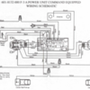
I'm trying to learn some LCRU2 boards I purchased.  I'm doing a test install just to see if I can get them working. The loco I chose has one dual wound pullmor motor.  I have tried hooking it up as pictured below just to see if I could get it to move with my cab1. 

I read through the original lcru documentation and it actually didn't say anything about using capacitors on these motors, however I did try it both with and without...

The attached photo shows the connections I've made.


The loco will not move.

I've programmed it to engine 99, and Programmed it to several different tmcc modes including mode 5 and 6.  I can see that it's getting reception because I've placed a multimeter across the frame of the loco and either the green, yellow, and blue wires.  They are getting voltage, usually approx 15v, that fluctuates as I manipulate the cab1 throttle and direction button, but it's usually at either 15 or 0 volts. Does this board work by varying the voltage delivery, or own to the motor?  And the loco never actually moves despite the voltage...  I'm stumped as to why...


Additional info.... I am programming in closed, running in open.  Cab one and tmcc base are both known good and working fine with other trains.  I am familiar with programming process and successfully confirmed it is working with other locos.  Not necessarily sure of the code type I'm using though...

First file is my setup currently.  Second file is full diagram...

Attachments

Images (2)
  • My current setup
  • LCRU2%20Dual-Motor%20Diesel%20Wiring%20Diagram
Original Post

Replies sorted oldest to newest

Sorry about the diagram, it looked a bit bigger on my phone, but it looks very tiny now that I'm no the computer.  I was able to verify that the light is toggling on/off with AUX2. 

Its definitely also worth mentioning that the bipolar caps I'm using are actually not.  I'm waiting on my bipolar caps to arrive, so I'm using two 2.2uf 50v  connected at the negative.  Like this
    ---(+ -)--- ---(- +)---
to form a 1.1uf bipolar....
a bit of googling told me this should work.  lol, maybe i shouldn't trust the internet so much. 
https://www.youtube.com/watch?v=aMluEC410eM

The directions for the dual wound pullmors were a bit confusing.  I may try to wire it to a dc can (using the diagram's ive found on this forum for doing so) or a standard pullmor and see if that works.

Here is the excerpt from the original lcru instructions for 2 position eunit pullmors.  Note that this is the document for the lcru and not the lcru2, but my understanding is that the motor wires (green/yellow/blue) wire the same on both??  What confuses me is that this section makes no mention of using the bipolar caps.  I am curious is this is part of my issue...


Engines Equipped With Two Position E-Units

Some of the older, more common Lionel engines, particularly those designated as O-27 types, come equipped with a two position E-unit instead of the more complex three position type. These engines use a double-wound field coil in place of the complicated three position E-unit mechanism to reverse motor direction. Wiring the LCRU to this type of motor is done as follows:

1. Solder the Yellow LCRU lead to one of the motor brush terminals.

2. Solder the Blue lead to the remaining motor brush terminal. LCRU Installation Manual ã Digital Dynamics 8

3. Identify the two field windings on the motor. One of the coils is wound in green colored wire, while the other is an orange color. Select one of the coils, it makes no difference which, and connect it to the GRN LCRU wire. The other coil is not connected and its end should be wrapped with electrical tape.


Dual wound fields are easy, for connection to the LCRU, just ignore one field, leave it unconnected.  The two field coils should both be grounded to the motor frame on one end.  The field (green) wire connects to the field coil you're using, and the armature connections go to the armature connections.  The caps the way you connected them will work, that's a classic way of making a non-polarized cap out of two.

Did you test the Pulmore by itself?  Wire one brush to one of the field connections, and connect power to the other brush and the frame ground.  If the motor doesn't run that way, fix that first.  Swap the two brush connections to reverse the motor direction and see if that works as well.

Unfortunately I'm still not able to figure this out on my dual wound pullmor.  The LCRU2 works fine when I set it up to use with a can motor so I have no reason to believe its broken.  It responds to tmcc commands fine.  I have a picture of how i had it wired.  I've foregone the capicitors for the time being until I've got it running correctly.  Foregive the mess as this it my test rig.  Ive rewired it more times than I care to admit.  As it sits it will run in just one direction.  When I change directions the headlight responds, but the motor buzzes a bit louder and tries to run in the same direction as before (and heats up).

Ive got yellow and blue each connected to a brush, green to the center terminal.  I have the gold/orange winding grounded on one end.  I believe I tried to ground the green winding on each end but neither worked successfully.  Any ideas would be greatly appreciated!


Attachments

Images (1)
  • 186491585_2901074413444714_4447664402520008504_n

Add Reply

Post

OGR Publishing, Inc., 1310 Eastside Centre Ct, Suite 6, Mountain Home, AR 72653
800-980-OGRR (6477)
www.ogaugerr.com

×
×
×
×
Link copied to your clipboard.
×
×