
I decided to build a separate post for the Twin Pines Railroad. This continues to be a work in progress. A BIG THANKS to everyone who contributes to this forum. I've learned a lot and enjoy seeing how everyone approaches the hobby.

My train room is in a basement  space with the available layout space of 9 x 13.  Walls are at the top and left and right sides. The layout can run three trains separately or a single train with access to all rails. I am not set on any particular period as I like to run both steam and diesel. For now I am a "looper" who is trending towards scale 3 rail.

For the most part I have some of the BNSF merger family and bits of Canadian National (think Illinois Central and ICG) and UP/SP.  Outliers are a Pennsylvania GG1 and the NW 611 steamer. I grew up in Chicago and saw most of the larger road names running in the 60s.

All  I can say is, what I started with is in no way similar to what I have now and I expect that my next layout will be different that what exists now.

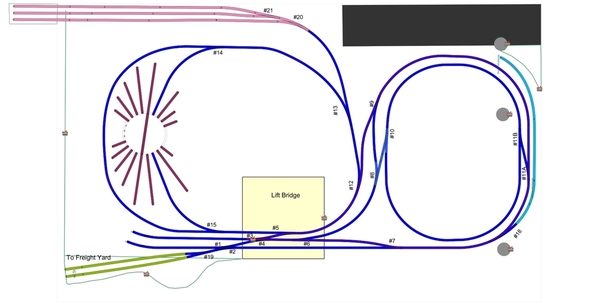
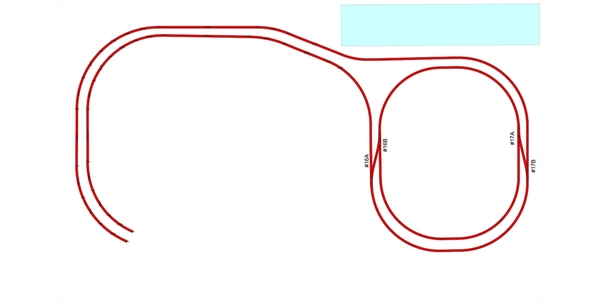
This is a "not quite" current Scarm image of the basic layout. I've since added another passing track along the top.

basement yard 5

This shows the layout as it basically is today. I still need to add the switch labeling to the new switches. The black track serves as my staging area / commuter station.

Switch Plan v2

This Scarm 3D gives an idea of the elevation changes on the layout. Its hard to get enough clearance for crossovers with such limited distance. The drawing is missing the added passing track. I can reach most everything with the open center. There are pop ups at the corners and another at the top right.  The bridges are either swing out of lift up in order to access the center, In an emergency it's a "dive under" as the table height is only 32 inches (will never do that again).  The double crossover is at an elevation of 4 inches (my zero elevation) and track either rises to about 7 inches or descends to 1 inch.

Layout 5

I realized I did not have enough yard or staging area and grabbed real estate wherever I could. Yes this makes for a track heavy layout.

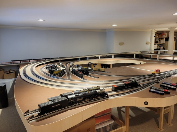
An early photo of the rough layout. Lots changed after I picked up a couple of engines which needed 072 minimums. Previously, I built to 042 minimum to handle passenger cars. Best I knew at the time. Notice the reversing loop in the foreground. There is a wye at the bridge which provides two separate loops for operations. I cannot operate in the middle, I get dizzy spinning while watching the trains loop around me.

IMG_2129

Torn apart and rebuilt, with the help of Scarm this time to fit the 072 curves.  This is where I wished I had never laid down the plywood deck. It made doing the track revisions much more difficult than it needed to be. But I was not going to start from scratch. Another mistake? - I could argue either way.

IMG_2216

Beginning to be happy with this layout, but the lack of staging would arise once more and end up in more tweaks.

IMG_2218

So after starting scenery and ballasting track, I decided I could get another 5 inches in depth to the layout for another long passing track along the back wall. Here I go again ripping up sections of my layout. Work in progress. Note the added track under the power station. Nice because it gave me more modeling space for a town above it and reduces the amount of visible track.

IMG_20201113_161523934

More to follow ... Jeff

Attachments

Images (7)
  • basement yard 5
  • Switch Plan v2
  • Layout 5
  • IMG_2218
  • IMG_2216
  • IMG_2129
  • IMG_20201113_161523934
Original Post

Replies sorted oldest to newest

Jay, yes a backdrop is actually done. I there is a post Dec 17th which shows a couple of buildings with the backdrop in the background. I have also posted several videos which capture portions of the layout. I am making progress to getting it into the shape for a "Big Reveal".  I am considering buying  cloud stencils to do my side walls since I don't have room to hang anything.   

GRJ - I tried to build with no more than 2.8% grades. There are a couple of spots pushing 3.8% according to scarm - although I did adjustments as I built to minimize the grade, particularly at the turnouts. So what on scarm was supposed to be 6 1/2 to 7 inches clearance ended up at 5 1/2.  Visually most of the adjacent track is on a down grade while that next to it is going up, so even at a 2.5% grade it looks like 5%. The most visible spot is left of the dbl crossover where the track is diverging vertically in order to get cross over clearance further around the bend. While operating, the longer trains slow down a bit going up and speed up going down when running conventional. Using DCS it maintains constant speed. Without the space savings of the crossover I could not get the vertical clearances and could not build this layout.  NOTE: I went back with a level and measured the grades at various points.  My steepest grade is 13/16" over a run of 28"  = 2.9% grade.  A few points have 3/4 rise over 28" = 2.68%. The rest of the grades are 1.8%.  Minimum tunnel clearance is 5 1/2" top of rail to bottom of tunnel / bridge.

This is where the software helped immensely. I kind of knew what I wanted, it showed what I could and could not do given my space constraints.  Really good reality check.

https://drive.google.com/file/...yLx/view?usp=sharing

I posted this in May 2020. I forgot about all the residue left by blue painters tape used to protect the track from the gray grout mix seen all around the layout. A quick wipe with alcohol cleaned it right off.

Last edited by ScoutingDad

3.8% is workable, but it's pretty steep.  I have 2.5%, and I was trying for 2%, just couldn't get enough run to make it happen.  At 3.8%, I can see some smaller and less powerful locomotives being limited as to what they can pull.  I tested my 2.5% grade with a Lionchief Plus Camelback that I converted to battery power, I don't have track power fully wired yet.  I ran the Camelback up the grade pulling eight Railking Aerotrain passenger cars, it had no issues, which gave me confidence.  The Aerotrain cars were selected as they're noted for having fairly high rolling resistance, so I thought they'd be a good test for the grade and the fairly small LC+ locomotive.

Got a little more work done over the past week or so, amazing how distracting selling off trains can be. Been focusing on the town area of the layout and thinking about how I want it to look given the space I have available. Added the wall in pink on the left and tore out the wall on the right.   

IMG_2626

Using my drill press and a couple of router bits I made the railings out of 3/4 inch foam insulation.  The foam is covered with a thin layer of mortar mix and painted. I should really scratch the foam, since there is not much for the mix to grab on to - it chips and flakes off easily - OK on wood though.

IMG_2629

Now with the top deck removed, more foam was laid down to provide walk ways for passengers. As much as I wanted the deck to be at subway door level, the curves just would not allow that to work. The outside curve is about 42 inches and the inside 31. (Next time the passenger station will have to be a straight section.)  The back retaining wall is masonite with thin foam strips all coated with mortar mix. I'll go back and paint to better match a concrete color. Planning to add arched detail sections between the back columns and add spot lights to the columns to illuminate the passenger areas.

IMG_2630

Top deck is back on with a coating of concrete paint color.  Decided to add spheres to the top of the pillars for a bit of detail interest.

IMG_2632

Attachments

Images (4)
  • IMG_2626
  • IMG_2629
  • IMG_2630
  • IMG_2632

Did a little more work on TPRR. Got the upper level painted and added ballast to the terminal track all the way out to the 4 way yard switch. 

Still trying to decide what I want on this upper level. I have several buildings I could assemble. Need to add lamp posts and below ground lighting. I like the way the rails came out.

IMG_2634

A view of the terminal. Arches added and painted. Printed a few "old" travel posters and hung them on the retaining wall across from the terminal. I may add a "frame" around them.

IMG_2635

A bit of an illusion - the gray section is the retaining wall. I added passengers to the last 'eL' and need to add them to the 3 other subway cars. They are 1:50 scale people and pretty narrow, but fit well in the tight space of the cars.

IMG_2636

Still need to do a touch more ballasting and lay down some grass. This section is about where I want it. The right side is a backdrop I painted a while ago. The back right with the trees lifts out completely so I can access track for maintenance as needed. This section blends pretty well with the backdrop so the eye does not notice the transition. Paint is a little more subtle in person.  It would be a lot easier popping up through the space if the table were 40 inches off the floor rather than 32. The light ballast is decomposed granite purchased at a feed store - called starter chicken grit. Has some nice color variation. And at $9 for a 50 pound bag it can work well in places. I prefer a dark grey for my main lines since it tends to hide the middle rail.

IMG_2633

Attachments

Images (4)
  • IMG_2633
  • IMG_2634
  • IMG_2635
  • IMG_2636

Marty (McFly?) - More than likely if the Twin Pines never existed, the town and RR would have a different name - but "lone pine" could have been a choice : )  The name stems from a resort in the Spooner Wisconsin area my dad owned in the 50s and 60s - Twin Pines Resort on Twin Lake.  The twins were a red pine which had a common trunk until about 4 feet up and then split into two. Unless the DeLorean hit it when the tree was young, the DeLorean would be totaled - it was a big old growth tree. 

I have an idea for modeling a twin red pine tree and placing it in the center of town's main road. So yes there is a chance a vehicle could run into it. I don't have room for a "parkway" but a tree island will work.

9x13 is a really challenging space to work with - lots of compromise needed, especially if you want to have 072 curves to run the big stuff and still have visual and operating interest. 

twin pines n

Attachments

Images (1)
  • twin pines n
@MartyE posted:

OK so I have to ask, if a Delorean runs over one of the pine trees back in 1955, does your Railroad become "The Lone Pine Railroad"?

Nice work.  I've booked marked this thread as I have a similar space to work with.

@ScoutingDad posted:

Marty (McFly?) - More than likely if the Twin Pines never existed, the town and RR would have a different name - but "lone pine" could have been a choice : )  The name stems from a resort in the Spooner Wisconsin area my dad owned in the 50s and 60s - Twin Pines Resort on Twin Lake.  The twins were a red pine which had a common trunk until about 4 feet up and then split into two. Unless the DeLorean hit it when the tree was young, the DeLorean would be totaled - it was a big old growth tree.

I have an idea for modeling a twin red pine tree and placing it in the center of town's main road. So yes there is a chance a vehicle could run into it. I don't have room for a "parkway" but a tree island will work.

9x13 is a really challenging space to work with - lots of compromise needed, especially if you want to have 072 curves to run the big stuff and still have visual and operating interest.

Jeff, thank you for the history behind the name for your layout.

Yes, 9x13 is a tough space for 072 curves.  I gave up on the idea of including them myself early in the designing process in my 11x11 room.  As it is the layout ended up being about 9x11 with a little peninsula in the opposite corner from the door since there is a big sliding glass door on the adjacent wall.

Pennsynut - to me it seems like this is taking forever. I have lots of ideas and get stuck trying to figure out what to do first. Then the CEO walks in and ask why certain sections are not done. Of course she is right, but I was focusing on my town area and left others devoid of any work - no ballast, backdrop - so those areas do not look very good. (Same area as the EP-2 photo - track laid but not much else)

I really should take the advice others have offered - do something on your layout every day.  Or as Nike used to say " Just do it" .

After rebuilding my layout at least three times, all by modifying existing areas and building on top of the old, I finally reached the conclusion, when it comes to track, it is better to rip everything down to the base and restart. I saw an area where I have a dip on a curved switch which sometimes causes a problem. I think the only viable solution is shimming the track because this area is already landscaped and ballasted. I really thought the base was level when I laid the track.

A couple of dips on my track developed over time and I shimmed them well after the area had been sceniced. As for trying to "get it all done for goodness sake", for me it is still taking years. In some places I made temporary mockup scenery on cardboard until I finally came up with a final plan. But we all know there is seldom a final final plan when it comes to model railroading. Carry on sir!

Made a bit more progress on Twin Pines Rail Road.  It is nowhere near where I want it to be, but here are a bunch of photos so you can see around the entire 9x13 layout.  The right side of the layout is still a work in progress as soon as I can figure out what will look OK in the space.


IMG_2641IMG_2642IMG_2644

The girder bridge is printed cardstock, walls are pink foam the portal is a double wide cut down by about an inch to give curve clearance on my larger locos.

IMG_2645IMG_2646

The CEO placed the Christmas tree, snowman and presents in the square. A real surprise and fitting around Christmas.

IMG_2647

The hill on the left is calling for more pine trees. The landscape behind the tracks are in two sections which can be easily lifted out, so I can pop up through the corner.

IMG_2649IMG_2650IMG_2651IMG_2652

The hill in the corner used to be much taller but did not look right - so off came much of the bottom. It also provides space for an incoming rail line and another siding to "store" trains. The foreground space will have an Atlas switch tower - if I can get my hands on one. Maybe a Peco tower depending on shipping from the EU. This is a decent example of using chicken grit as ballast for the terminal rails and dark grey Scenic Express ballast for the mainlines. I did end up using paving sand between the track and covered with ground foam. (Frustratingly - I cannot get my WS static grass applicator to get the fibers to stand up - If I pour glue on my grounding rod, then it kind of works - argghhh.)

IMG_2653

Terminal waiting for the Plastruct twin vertical tanks.  I'll probably add 4 inches to provide room for a road and the tanks in front of the building and pump rack.

IMG_2654

There are 3 bridges in the photo, the middle one is hidden by the Lionel bridge. I had to raise it 3/4 of an inch off the deck to provide clearance for my husky stacks. Two of the bridges are lift outs with banana plugs providing power and removal if necessary. The MTH bridge swings out with a 4 inch door hinge.

Well that's my space and layout so far.  Jeff

Attachments

Images (12)
  • IMG_2641
  • IMG_2642
  • IMG_2644
  • IMG_2645
  • IMG_2646
  • IMG_2647
  • IMG_2649
  • IMG_2650
  • IMG_2651
  • IMG_2652
  • IMG_2653
  • IMG_2654

OK Guys - regarding the bridge - I did get the idea of using cardstock from RSJB18 (Bob)   See my post on page 993 describing the bridge in "What did you do ..."  I made this bridge twice once in grey and then again in color. I used a laser printer - however the CA does not stick very well to the waxy laser ink - I would use ink jet when I do it again. Also color all the edges before you glue together, once coated with CA nothing you do will cover the white edge.  There are several posts of the bridge in my posts - a favorite photo location for me. 

Wow, Jeff, really great progress. I was worried about your grades too, but they seem to be working out.

A couple of people have commented on the difficulty of using O72 in a 9' x 13' space. 108"  is of course plenty of width for 72" diameter track- the problem is if you want a complex track plan, multiple loops and engines to be able to run anywhere on the layout. Since, when you come down to it, most of us run a lot more than we switch, here is one possible solution.

Simply make the O72 a completely different layout on another level and unconnected to the other level ( either above or below) and run the big trains on that. On the second level, use a smaller radius and a more complex track plan and do most or all of your switching on that level.

Last edited by Will

Will - all that yours on the "Art Website"?   impressive.

Turns out the upper/outer level is a minimum of 72" diameter - I don't know for sure because I had a box of used Ross track that went over 88".  Taking a page from many on the forum, where it fit, I would place the largest diameter curve I had on hand in the middle and finish with the 072. My second level has a mix of 072, 062, 054 and  042. The inner is no more than 42" with the depot having 031" at the tightest diameter. A couple of my MTH premiers supposedly minimum 072 run just fine on the tighter curves.

For me it was important to be able to run an engine on all three tracks - given the biggies were not going to be able to do that - so all the tracks need to be interconnected. Basically I wanted more than a 30 second loop around the track.

My biggest issues are - forgetting to put bridges back in place when changing from a test run to run on the layout (and the other tracks with the missing bridges) and forgetting to electrically connect all the tracks into one common feed.  I get to a turnout, get halfway through and oops no power. DRAT!

Overall running the big iron in a small space is really hard to do - other than a big circle. I was playing with SCARM and realized I need 19 feet just to have a modified dogbone with 072 - double mainline needs a touch bigger. This one is 13x23 and where do I put a multiple track passenger station (14 feet minimum length) - back is the only feasible place.

13x23b idea

The Black Diamond RailRoad is built on a similar foot print and will probably be what I model on my next layout - with a little customization of course.   

Attachments

Images (1)
  • 13x23b idea
@ScoutingDad posted:
Overall running the big iron in a small space is really hard to do - other than a big circle. I was playing with SCARM and realized I need 19 feet just to have a modified dogbone with 072 - double mainline needs a touch bigger. This one is 13x23 and where do I put a multiple track passenger station (14 feet minimum length) - back is the only feasible place.

It is possible to get a nice run in a 13x23 space, my layout is roughly 24 x 12 and all my curves are O72 or larger.  I went with a large folded dog-bone that has a second level.  My dog-bone mainline has 140 running feet of track, and there are three smaller loops that I can either run on or park things on.  I also incorporated the capability to reverse direction on the main dog-bone, something that I felt would be mandatory.

Here's two shots, on the lower left of the main level plan, the elevated section ramp starts and wraps around the back.  The elevated section is depicted in the second graphic.

Main table level track plan

Elevated level track plan

A shot from the front showing the grade

Attachments

Images (3)
  • mceclip0
  • mceclip1
  • mceclip3

Did more track ballasting and ran out of the dark gray Scenic Express. Probably need one or two more gallon containers.  Updated the SCARM drawing to show what is now on the layout. I do not see any more room for track. : ( 

With this last update - I think I now have more curved turnouts than traditional ones. They are a real space saver as there is not much straight track on this configuration.

TPRR Final bTPRR Final

Attachments

Images (2)
  • TPRR Final b
  • TPRR Final

Finished the Plastruct storage towers and placed them in the fuel depot.  Still have to decide which decals should be on the depot. The asphalt is the mix of fine cinders and white glue described by Ericstrains - I think it came out well - thanks Eric !

IMG_2658IMG_2660IMG_2663

Yes I know we do not put petroleum products into carbon dioxide or liquid nitrogen tanks. 

Attachments

Images (3)
  • IMG_2658
  • IMG_2660
  • IMG_2663

Which are you leaning towards Jeff? To my eye the chicken grit is too light but the #16 looks more natural.

Jay, I am not a fan of light ballast, but its is used all over the Midwest by the railroads - limestone is pretty cheap.  This layout will likely be coming down in a year or so (due to a planned move), so I wanted to try a few ideas for the next layout.  The grit is decomposed granite so it has all kinds of colors so its not bad. I think I would tumble it for a while to knock off the sharp edges if I were to use it again, but I think buying commercial ballast is probably a better idea. (But - grit is super inexpensive) 

The #20 is supposed to be O scale size. I ended up with the #16 because it was super cheap from Trainz and I needed more ballast to finish the tracks. I think I like the #20 better color wise. The photo angle is giving a slight change to the Ross track above and below - ignoring the brown ties of the Gargraves flex top right. The #16 is more uniform in color, with the #20 having the lighter grey pieces sprinkled in.

Working on the detail is therapy in these days of Covid.  Anyway just building up skills so I know about what I can do when planning the next layout.

Saw a layout plan where there was no lift-ups or lift-outs, but used helixes to turn around (and up). Pretty interesting but it was an HO layout.   by mpeterll  I will run a couple of ideas on Scarm to see how much room that would need for O and 72 and 88 curves (double mainline).

I think you all may be getting the idea I cannot leave things alone. Picked up a couple of MTH corner buildings and the MTH station and started figuring out where to put them on my layout. The station did not look that good in its intended spot as a station, so reconfigured the town a bit.

The station is now the Twin Pines Inn - signage since added.

IMG_2710

The bar and new corner buildings are on the extended area of the town.

IMG_2711

I pulled all the incandescent lights from the MTH buildings and replaced them with 12v led strip lighting. 1st and 2nd floors are independently controlled and on dimmers.

IMG_2712

The rest of the photos show how this area can come apart. All the lighting has M/F disconnects which makes pulling sections completely off without unscrewing wire terminals simple. 

IMG_2713IMG_2714

The hole in the center shows how "c" sections were used to support the upper structures but also allow just enough room to stand up in this area. Now if only the entire layout was only 12 inches higher it would be much easier to get up through the hole.  I made it at 32 inches to make it easier for the grand kids. Good thing they are now much taller, next layout will be at least 42 off the floor.

IMG_2715

Even the landscaping on the right is removable - its just cotton batting over pink foam.

IMG_2716

Attachments

Images (7)
  • IMG_2710
  • IMG_2711
  • IMG_2712
  • IMG_2713
  • IMG_2714
  • IMG_2715
  • IMG_2716

Here is a link to trains running on Twin Pines RR. Should give you a better idea of what the layout now looks like.  The yellowish tone is due to a halogen lamp adding needed light to the bridge area. The background has 2 10,000 lumen LED garage lamps adding needed video lighting - they are quite bright.

Hope you enjoy ... Jeff

TPRR May 2021 Trains Running

Last edited by ScoutingDad

Here is a cab view of the Twin Pines Rail Road. Sure looks different running down the rails.

I may try putting the camera at the very front of the car to see if it catches the turns any better. Otherwise I can set a wider camera angle.  The 40,000 lumens of 6000K LED garage lighting does make a difference in the video capture. Far less grainy and better color.

I can think of a couple of things I would do different next time. Like leaving the station slower and sounding the bell.  I did miss a switch which caused the camera car to derail. Did it again but it re-railed itself on the next turnout.

Total video is about 5 minutes - its probably a bit long but it covers all my interconnecting track. Running about 25 scale mph.

Hope you enjoy.  Twin Pines Cab View May 2021

Ongoing Saga - finished redoing my backdrop behind the town of Twin Pines. I like it much better than the undersized "mountain" previously in the background. Stitched together 2 layers of 1/2 inch pink foam, carved it a bit and glued down a layer of cotton batting. Painted a brown dirt color and added ground foam and leaves to add texture. Repositioned the mountain where I think it makes more sense.

Rough foam placement - I hardly ever throw anything away - never know when you can use pieces of this and that. This is a one piece section nearly 8 feet long.

IMG_20210701_205919271_BURST000_COVER_TOPIMG_20210701_205950057

Finished section

IMG_2741IMG_2742IMG_2743

A before photo - mountain barely visible behind the corner building and the Twin Pines Inn on the left foreground.

IMG_2711

That's all for now. 

Attachments

Images (6)
  • IMG_20210701_205919271_BURST000_COVER_TOP
  • IMG_20210701_205950057
  • IMG_2741
  • IMG_2742
  • IMG_2743
  • IMG_2711

Thanks Mark,  didn't take all that much time. I started too tall and kept trimming to get a reasonable height. Time for glue to dry and paint to dry was 90% of the time. Next time I'll have to get some better lighting.  I have so little space to maneuver its difficult to get certain camera angles.

Still thinking about re-doing the town. I think I'll move the Inn back where I originally had it and put in a couple of woodland scenic buildings I am working on in its place.

How is the back surgery recovery going?

Last edited by ScoutingDad

Well I went ahead and moved things around in the town. Ended up doing more re-wiring than anything else. I now have different connectors for my Miller 5v signs and for the building LEDs  and street lights 12v.  Not quite done with the Woodland Scenics store - lost momentum doing all the little detail painting and thinking about how to put LED chips into the goose neck lights that will illuminate the sign.

Also added a K-Line Interurban which arrived today from Stout.  1 day UPS delivery - the stars were aligned. These can be modified to run off the power poles. Next layout I have a plan for a 2 rail city line running off overhead wires. Really wanted a couple of the brass trolleys from a past auction but the hammer prices were more than I was willing to part with. One of these days. Considering they have been in a box for who know how long, once the contacts were cleaned, they run pretty nice. Interior lighting is good, interior details decent and the green/red running lights mostly switch in tandem forward and reverse.

The only Twin Pines buildings I did not move were the MTH corner buildings toward the back of the layout.

IMG_2748IMG_2749

Not super visible, but I added 5 LEDs under the theater marquee and one above to light the building medallion. These are on a dimmer to adjust to lighting needs.

IMG_2750

When I build the next layout the backdrops are going to the ceiling. Have to laugh, I have been watching the old painting shows on PBS and Create to pick up some techniques on scene painting. Besides the amazing way they add a little of this and a little of that and a touch of another to get the color they want - yet never mixing it uniform to have color gradation - its they way they build depth to a flat 2D canvas by painting layers back to front.     


IMG_2751

Have a great rest of the week everyone.  !!!

Attachments

Images (4)
  • IMG_2748
  • IMG_2749
  • IMG_2750
  • IMG_2751

Thanks David,  Next is to get out to the train shows and begin to pick up more little people and vehicles. No more room on this layout for more buildings except for a spot for a switch tower.  Still thinking about how to build a facade for a bowling alley. Already have part of a name "Tank's Pins and ???" or something like that. My dad was a semi-pro bowler in the late 40s and 50s and Tank was his nickname.  Next time I plan a visit to Nebraska ... - well you know how that goes.  ; )

Wow, I can't believe its been 6 months since my last update on TPRR.

But first, in that time Sue and I signed contracts on 2 homes in Michigan. Both deals fell apart due to inspection problems. One the owners refused to do $30,000+ in needed repairs and the other had soil erosion problems so bad the soils engineer told me he could not recommend buying at any price. This one had a dream layout room above the garage - 12  by 35 feet of finished and heated/cooled space just calling out for a railroad. Bummer - the home needed work but was otherwise solid. 6 acres with a meandering creek running through the middle, nicely wooded, of course that was what was creating the problem.

So on to the layout, when I built the layout I used 1/2 nominal plywood using 2x4 spacers to provide support. Over time some sections warped and other sections I goofed up during rebuilds. One section in particular was temperamental with my longer engines. There is a grade transition here where its down hill going to the right.  You might be able to see the hump above the hinge going back to the second support. There is also a turnout in this spot which none of my scale steamers liked.

IMG_2757

So after a bit to touchy surgery, I was able to take out the hump. My level shows no gaps so I expect this little challenge has been addressed. Still have to add a couple of supports to stiffen the road bed.  IMG_2781

While this was going on, I found a "reworked" section where I had goofed once again. I use Ross turnouts and use a feature where they provide a natural place for blocks. In this case I used an insulated pin to join the lead track to the turnout. This created a 6 inch unpowered section. If the trains were going fast enough (around 30 Smph) the only thing that happened was an occasional spurious toot from the engine.  However slower speeds and shorter spacing between the pick ups resulted in a dead engine. Of course it was at the other end of the layout where it is just inconvenient enough not to want to put up with. Next project on the docket. I will also improve the level there and try to take out a slight dip.

So here are a couple of pics of the TPRR with my recent purchases scattered about.

IMG_2780

Its socializing time at the Camaraderie Bar. No one minds the trains, they know they are important and what the heck, they all enjoy watching them go by.

IMG_2783IMG_2784

Attachments

Images (5)
  • IMG_2757
  • IMG_2781
  • IMG_2780
  • IMG_2784
  • IMG_2783
Last edited by ScoutingDad

Got around to addressing the "dip" at the back end of the layout.  I tried to use a framing level, but that was not working across the 072 curve.  So I trimmed a 6 foot piece of masonite to give me an idea on how off "flat" the track was. [Recall most of my layout is on some kind of grade so there is almost no "level" anywhere. So I use the term "flat" to describe track sections the otherwise may be level but at a grade up to 3%.] The masonite was sitting on the outer ties clipped to the outer rail. This allowed me to see the height differences as I moved from left to right. As a temporary measure I inserted shims on the back side where I have a pop up and better track access. Way off.

IMG_2839

Since I really could not tear out that section of the layout, I had to figure out a way to provide a solid surface under the track but also be thin enough to be able to shim along a 10 foot section.

On the foreground track, I was able to use 1/4 plywood with shims. Placed the track down, then the long level set on the track to check for gaps. Shimmed where necessary. Being frugal and not having 1/2 ply, I cut homosote for the background track roadbed. Shims are glued in place with the road bed ready to go down for another final check for any track gap against the level.  Of course neither 1/4 ply or 1/2 homosote is any good for structural stiffness.  Skipping a couple of steps along the way but you get the idea.

IMG_2842IMG_2843

The solution was to lay a bed of setting mortar on the layout deck, so the roadbed would be fully supported underneath. And that is why the shims were glued in place prior to mortar going down.

IMG_2845

In the photo above, you can see a gap between the 1/4 ply and layout deck. This was taken off, mortar applied and the 1/4 ply reset.

Foreground and background roadbeds are down. Now its time to let the mortar set before screwing down the track and doing a test run.  There was a lot of back and forth trying to get both track sections flat. I found I could get a better idea on flatness using the level on top of the rails instead of on the road bed.

IMG_2846

Attachments

Images (5)
  • IMG_2839
  • IMG_2842
  • IMG_2843
  • IMG_2845
  • IMG_2846
Last edited by ScoutingDad

After a bunch of fiddling around,  got the track section repaired, ballasted and somewhat scenic'd. I almost never pop up in this location of TPRR but decided to takes a few images of the track work looking "West". Rails are still not perfectly flat, but pretty close. The track had a few slight bends which I could not completely straighten. The 2 right tracks were completely removed along with the roadbed. The furthest right track was added last year by sliding the entire layout "south" (to the left) a few inches. For me the extra track made a huge difference in operation and "look". Yep - a track heavy layout. From right to left - track 1 and 2 form loop 1 (either can be the main); track 3 is the interconnecting section for loop 1 and loop 2;  track 4 is middle loop 2;  track 5 is inner loop 3; the rest of the track form the "yard". Each loop can be separately run convention or DCS or TMCC.

IMG_2848IMG_2850

IMG_2852

While I was working on the section, I finally figured out what to do with the Twin Pines Inn and where to place the magnificent twin pine (as yet grown).  This is the pop up at the Nor'eastern corner of the layout. I previously has a little mesa and a feeder track coming from off the layout.  [Gosh I wish I had made the table height more than 33 inches from the deck - have to be a contortionist to stand up.]

IMG_2847

Here is the Inn in its most likely final position.  The twin pine will be off to the left. I am considering a large oak behind the Inn so its branches overhang the Inn.  The track to the right will be rail service to the Inn.  A low brick or stone wall will separate the Inn and track.

IMG_2853

What really gave me this idea was looking at timetables of the Milwaukee Road Hiawatha which used to serve Minoqua, Wisconsin - an annual vacation location for my family. Rather amazing to me to see the vacation spots people trained into prior to the advent of the interstate highway system. Next time I am up there I am going to find out where the line terminated. I think I know where it did but never registered. 

Attachments

Images (5)
  • IMG_2848
  • IMG_2850
  • IMG_2852
  • IMG_2847
  • IMG_2853
@ScoutingDad posted:

After a bunch of fiddling around,  got the track section repaired, ballasted and somewhat scenic'd. I almost never pop up in this location of TPRR but decided to takes a few images of the track work looking "West". Rails are still not perfectly flat, but pretty close. The track had a few slight bends which I could not completely straighten. The 2 right tracks were completely removed along with the roadbed. The furthest right track was added last year by sliding the entire layout "south" (to the left) a few inches. For me the extra track made a huge difference in operation and "look". Yep - a track heavy layout. From right to left - track 1 and 2 form loop 1 (either can be the main); track 3 is the interconnecting section for loop 1 and loop 2;  track 4 is middle loop 2;  track 5 is inner loop 3; the rest of the track form the "yard". Each loop can be separately run convention or DCS or TMCC.

IMG_2848IMG_2850

IMG_2852

While I was working on the section, I finally figured out what to do with the Twin Pines Inn and where to place the magnificent twin pine (as yet grown).  This is the pop up at the Nor'eastern corner of the layout. I previously has a little mesa and a feeder track coming from off the layout.  [Gosh I wish I had made the table height more than 33 inches from the deck - have to be a contortionist to stand up.]

IMG_2847

Here is the Inn in its most likely final position.  The twin pine will be off to the left. I am considering a large oak behind the Inn so its branches overhang the Inn.  The track to the right will be rail service to the Inn.  A low brick or stone wall will separate the Inn and track.

IMG_2853

What really gave me this idea was looking at timetables of the Milwaukee Road Hiawatha which used to serve Minoqua, Wisconsin - an annual vacation location for my family. Rather amazing to me to see the vacation spots people trained into prior to the advent of the interstate highway system. Next time I am up there I am going to find out where the line terminated. I think I know where it did but never registered.

The Line went to  Star Lake.   The north woods HI  actually went from New Lisbon  to Star lake, where it was turned on a Y.    A  Regular Hiawatha  would have  had several cars   that were switched out in New Lisbon and taken North o the North Woods Hiawatha, up to the resorts in Northern Wisconsin, I havent been over there since November ,  The Log Station , in Woodruff and the bridge over the  lake in Minocqua    , nothing much in Star Lake, most everything is Built over or grown shut still a beautiful  area

Got a little distracted with the paying job, and selling a few items here and on the bay.

After reading forum discussions on track planning I picked up John Armstrong's book "Track Planning for Realistic Operations".  I do not think it would have helped when I first started my layout iterations, but now I understand the wealth of information contained therein. Well worth the $12 bucks from a used book seller. Thanks to whomever cited that book.

Toying with how I want the Twin Pines Inn area to look. I've got an idea for the lone twin pine, but went ahead and started the build of a burr oak tree. As usual watched a lot of how-to videos and @Sarah 's build of her trees.  Link to Burr Oak image

Here is a bunch of 19 and 20 gauge wire roughly 20 inches long. The intent was to build a 60 scale foot oak.  Burr oaks are gnarly and usually wider than tall. I also wanted sturdy roots coming out at the bottom.

BurrOak1

Then it is a matter of twisting bundles of wire together around the core. A wrap of wire around the trunk helps stabilize the wire. I've seen some of these with 6 foot diameter trunks, so the wrap works fine to thicken the trunk.

BurrOak2

For the branches it more twisting and folding and more twisting. Wear safety glasses on something this big, hard not to poke yourself with the sharp wire edges. Bottom photo is with the first coat of heavy modeling latex over everything. I'll apply 2 or 3 more coats and cover everything with fine coffee grounds. I dump the used stuff in a sheet pan and cook off the water.

BurrOak3

The plan is to use sedum at the ends of  the branches coated with several layers of dilute PVA to give a little strength. They are quite brittle. The war gaming folks don't use glycerin as it makes things too floppy, so they coat with PVA to enable handling. After that I'll start with Scenic Express Super Leaves. If too sparse I'll try either Woodland Scenics Fine Leaf Foliage or do the fiber followed with ground foam and leaves method.  This is sedum before I knock off the spiky flower buds with a sturdy brush.  IMG_2883

Attachments

Images (4)
  • BurrOak1
  • BurrOak2
  • BurrOak3
  • IMG_2883

I think this burr oak build is going to work!

These are the sedum tips, dipped/immersed into 4:1 water/glue, allowed to drain for a minute or two, then sprinkled with super leaf.   Trying to decide to spray with hair spray to get the extra fix or spray with a thinned modge podge or the modge podge canned spray.  I have Krylon matte but not sure it has any holding power.

IMG_2888

I like the effect of the brownish red  color peeking through the leaves.

IMG_2889

Here is the wire tree armature with a second coat of latex then dusted with coffee grounds while still wet. I worked in sections as the latex skins quickly. I left the ends bare so as not to interfere with gluing the leaves on.  I think I will need 80 to 100 of the leaf bunches. Making the bunches goes pretty fast, gluing them to the tree is going to take time. I am leaning toward making all the leaf bunches and then applying, as opposed to gluing the stems on and then applying the leaves.

IMG_2890

Attachments

Images (3)
  • IMG_2888
  • IMG_2889
  • IMG_2890
@ScoutingDad posted:

I think this burr oak build is going to work!

These are the sedum tips, dipped/immersed into 4:1 water/glue, allowed to drain for a minute or two, then sprinkled with super leaf.   Trying to decide to spray with hair spray to get the extra fix or spray with a thinned modge podge or the modge podge canned spray.  I have Krylon matte but not sure it has any holding power.

IMG_2888

I like the effect of the brownish red  color peeking through the leaves.

IMG_2889

Here is the wire tree armature with a second coat of latex then dusted with coffee grounds while still wet. I worked in sections as the latex skins quickly. I left the ends bare so as not to interfere with gluing the leaves on.  I think I will need 80 to 100 of the leaf bunches. Making the bunches goes pretty fast, gluing them to the tree is going to take time. I am leaning toward making all the leaf bunches and then applying, as opposed to gluing the stems on and then applying the leaves.

IMG_2890

Coffee grounds , is brilliant, after I carved my park in the clay It always looked too smooth to me. I also like you leaf material

I am going to take @Dave Koehler 's advice and use modeling clay around the base. Otherwise it will take several more coats of latex to hide the wires.  Bought a bit of oven fired clay, 15 min at 275.  We will see how that turns out. Hopefully the latex won't break down at that temp. [Supposedly it will take 325 and in the process will vulcanize.] 

I think I got the coffee grounds idea from Sarah.  The dirt around here is either clay or has a lot of organics - neither of which are helpful for simulating dirt.

Last edited by ScoutingDad

On going saga of building a Burr Oak tree. The intent is to place the oak behind the Inn as seen in the photo.  I have far less room behind the Inn than I thought. This is going to have to be a 1/4 tree in order to fit. As you can tell by the building this is a big tree. But is is sitting about 6 inches higher than it really is. 

Concepts are one thing the actual build is another.  A couple of things about using the sedum heads. I really like the branching the heads have, but I really do not "care" for how flat the heads are. As a trial, I used shrink tubing (white) to slip over the wire branches with the sedum stems inserted. This allowed me to add multiple branches to a single wire.  I did not heat shrink them, but will probably buy black tubing and use those to hold everything in place while final gluing.  An easier way to do this would be with poly fiber. That method is OK, but I think the leaves get too dense making the tree too dense. Maybe the sea foam armatures are the way to go after all.

Another thought - if I were to do a "puff ball" tree line background, these would work really well planted in a foam backer.   

As for looks, I think the tree above the roof line needs to be no more than the total height of the Inn and maybe just the height of the second floor and roof.  Basically remove the bottom branches and shorten the entire tree.  What do you think?   

IMG_2891

Attachments

Images (1)
  • IMG_2891
@RSJB18 posted:

IDK Jeff- I like it but I wouldn't want to sleep on the second floor in wind storm.......

The tree needs to be more dense. The clumps all on the end don't look realistic. Can you split some of the sedums and glue them down the branches closer to the main trunk? It would fill it in more.

Agreed, but the height  looks good. filling in from the sides, will flush it out.  and every one needs to remember, most of the model train layouts , we have seen the trees are way to small .  I live in an area where the trees are 40 to 80 feet tall !

Thanks @Dave Koehler  @RSJB18  The tree certainly needs more fill-in.  I was trying to get an idea on size and placement of the leaf clusters. In order for this tree to fit in the corner, I will have to bend or remove branches to the point the tree will look like an 80 degree pie shape from above. If I can bend the branches around I should have enough wire stubs to add leaf clusters to fill in. The use of the shrink tubing is a help but the stems are going in nearly parallel to the wires.  I'll have to figure out if I can get 30 to 45 degrees out of the tubing  to get more "spread".  I can then glue them in place for a more permanent set.

As this is a work-in-progress and a learning experience - next time I would knock nearly all of the flowers off the sedum heads,  paint the stems, apply the leaf material, seal and then apply to the wire tree.  The wires are about the right length if I was adding poly. But with the stems adding 2 to 3 inches I'll be doing a bit of wire trimming. 

As far as proportion, the Inn is 9 inches to the roof line, the top of the tree is 18 inches. A full grown Burr Oak tops off around 60 feet, so from 2 perspectives the height is about correct to the prototype and it looks reasonable next to each other in this photo. Although I could make an argument to shorten it by 2 to 4 inches to reduce its visual impact on the rest of the layout.  I can certainly duplicate its height with the twin pine I will model later.  Looking at this image I would love to put this tree next to or a little behind the inn off a corner. I just do not have the room - its really tight - I'll have to consider alternatives - maybe ...


IMG_2896

A close up of the leaf clusters. I think the leaves look pretty good. In order to get around the flat head look I might be able to separate the clusters into smaller units and hot melt them into a larger, more "natural" cluster. There are 3 different super leaf colors in this mix plus the rust coming through the stem. You can see the texture in person, but the camera will not pick it up at a distance.

IMG_2897

Thanks for the feedback - it helps to think about alternatives and different approaches.

Attachments

Images (2)
  • IMG_2896
  • IMG_2897
@ScoutingDad posted:

Thanks @Dave Koehler  @RSJB18  The tree certainly needs more fill-in.  I was trying to get an idea on size and placement of the leaf clusters. In order for this tree to fit in the corner, I will have to bend or remove branches to the point the tree will look like an 80 degree pie shape from above. If I can bend the branches around I should have enough wire stubs to add leaf clusters to fill in. The use of the shrink tubing is a help but the stems are going in nearly parallel to the wires.  I'll have to figure out if I can get 30 to 45 degrees out of the tubing  to get more "spread".  I can then glue them in place for a more permanent set.

As this is a work-in-progress and a learning experience - next time I would knock nearly all of the flowers off the sedum heads,  paint the stems, apply the leaf material, seal and then apply to the wire tree.  The wires are about the right length if I was adding poly. But with the stems adding 2 to 3 inches I'll be doing a bit of wire trimming.

As far as proportion, the Inn is 9 inches to the roof line, the top of the tree is 18 inches. A full grown Burr Oak tops off around 60 feet, so from 2 perspectives the height is about correct to the prototype and it looks reasonable next to each other in this photo. Although I could make an argument to shorten it by 2 to 4 inches to reduce its visual impact on the rest of the layout.  I can certainly duplicate its height with the twin pine I will model later.  Looking at this image I would love to put this tree next to or a little behind the inn off a corner. I just do not have the room - its really tight - I'll have to consider alternatives - maybe ...


IMG_2896

A close up of the leaf clusters. I think the leaves look pretty good. In order to get around the flat head look I might be able to separate the clusters into smaller units and hot melt them into a larger, more "natural" cluster. There are 3 different super leaf colors in this mix plus the rust coming through the stem. You can see the texture in person, but the camera will not pick it up at a distance.

IMG_2897

Thanks for the feedback - it helps to think about alternatives and different approaches.

corners cam be tricky! , and it is easier to clump a group of trees together

Finally got back to the layout - but really to the Burr Oak.  I stripped the tree down to bare wire branches and started re-attaching the limbs.  I did not have any black shrink tubing so decided to try hot melting the limbs. Worked OK, but is messy. Next time I'll use the black shrink tubing to hold the limb in place and then cover with a mix of white glue and coffee grounds (or latex plus coffee) to set them in place.  In places where I had extra wire I twisted it around the stem to hold better.  I also took the longer stems and added branches (leaf clusters) to get the 3 dimension look. The heads themselves are rather flat disks.

NOTE: I am going to try to use the following consistently to describe the build:

  • Wire arbor and wire branches to describe the bulk of the tree and wire branches are the attachment points for the sedum limbs.
  • Limbs refer to the thicker woody part of the sedum stem
  • Leaf clusters refer to the sedum flower heads with leaves attached.
  • Branches (as opposed to wire branches) refer to smaller groups of leaf clusters glued to the limbs.

I ended up trimming the wire branches down to get the right spread of the tree. Covering the wire with multiple coats of latex and coffee grounds worked really well. I could freely bend the wire to get access to glue in the limbs. Once attached just bend back into place. Once I figured out what I was doing, work progressed quickly. The shiny parts seen in the photo are the hot melt holding the limbs to the wire branches. Here is the tree with 40 to 50 limbs attached to the wire branches. I made another 40 or so to finish the lower portion of the tree. 

BurrOak4

Here is a better close up of the leaves. The 3 different super leaf colors look pretty good. Using 60% to 80% of one leaf as a base color and the other two as highlights seems to work best to my eye.  I could vary the leaf density by using less leaves and by removing more individual sedum head flowers. Taking too many off looks a little sparse but in the right place looks fine. 

BurrOak5

What else would I do different?  Making the limbs with the branches and leaves is the best way to do this. You have really good control of the leaves and density on individual limbs and branches and you can get extra coverage on the underside of the sedum head. But they are a little brittle. I would spray with an adhesive to get better leaf attachment and fine stem strength once assembled into branches. I have a bottle of modge podge spray to try for coating the new limbs and the already built portion of the tree.  I am convinced using the shrink tube to get an initial attachment (branch to wire) is the best way to start assembling the tree.

I found out lightly rubbing the dried flower heads together gets the flower heads off quickly and more thoroughly. Pieces that break off were probably not going to stay on anyway. A brush works ok, but is slower and you have to support the head. 

I do like dipping the flower heads in about 3 inches of "scenic" glue. This thoroughly coats the flower heads and a portion of the sedum stem (in hopes it gives a little more strength). I let the glue drain off for a minute or two prior to applying the leaf material. Shake off the sedum stem in a bag or box. Excess glue ends up in the excess leaf material and creates clumps. So I make enough leaf mix to only do 5 or 6 branches to minimize leaf waste. Even if you end up with dry leaf clumps you cannot easily break apart, you now have extra ground growth for elsewhere on the layout. Mixing small batches is also good because there will be variations in each batch creating slight color variations in the finished tree.

Not sure if this is good or bad. After a week or so the latex had cured and remained flexible. Good because it was not damaged by all the wire flexing I did. Maybe no-so-good, because it was relatively easy to pull off the latex from the wire branches meaning there was not a lot of holding power. Of course what will hold fast to thin smooth wire?

Attachments

Images (2)
  • BurrOak4
  • BurrOak5

Bill, time is all in the planning and then dry time. I estimate 30 min to form the wire tree and fiddle with it 15 min for coating with latex and coffee several times. 30 minutes max to do the leaves and maybe an hour to attach the branches to the wires. This is a 20 inch tall tree so there are going to be 50 to75 branches to attach. That will take time especially if picky like me. Of course this is a foreground tree meant to attract attention. Sara`s tree would take half the time because its more vertical and the material she used for the leaves would work well.

I've posted on making different types of pine trees using dowels with furnace filters as needle supports and wire branches with static grass for needles.  Decidious trees I've made with twigs and poly fiber and or furnace filter material covered with the super leaves. For me the wire arbor is the way to go. I think the fiber gets too dense. But could be ok for deep background trees/forest. Essentially puff ball trees.

If you have any dried sedum around, those could be glued together to form a 4 or 5 inch tall tree without too much trouble. I could not get hydrangea heads to work.

Luke Towand has a nice video on making wire trees for ho scale. He uses fiber static grass ground foam and leaves for the leaves. There is a product called seafoam a plant which could look good with some fiddling. I do not like the adhesive spray, it sticks well, but dries slow and will collapse the structure if if you compress it at all.

@Tom Tee  HI Tom thanks for the kind words.  Yes it is great to be a young 66 in August. !!!

We are hoping to buy the next house before the end of this year, we will see. We found a great house which literally backed up to an interstate. Road noise was intense. Not much decision to make - a hard no- we currently live about a mile from I57 and can hear the high pitched road noise at night - not willing to live with that any more.

Regarding Twin Pines - I knew this was going to be short lived, but watching all you and others have done has allowed me to experiment with different techniques. I love learning new stuff and get quite a bit of motivation trying out new things. The CEO commented the other day on how I am able to just go ahead and launch into things I have never done before and am not afraid to do it. I just suppose I consider myself handy.

I do intend to complete a couple of more details on the TP before it comes down for good.  Don McCuaig (former forum member) did a great video of his layout called the "Last Run" - I plan to do something similar, but will not be able to reach his Emmy award level skills. Should be fun trying though.  So I know how I will build the next one, I know some of the elements, but until I know the space everything is up in the air.  My dream besides having the 3rail, includes a small two rail town trolley system with working overhead wires and a point to point 2 rail to display and run my scale European crocs and passenger cars and "wagons". I think I can work those in together because they do not need to connect with the 3rail.

So much for a short answer. Carpe Diem  --- more accurate translation "enjoying a moment that is rooted in the sensory experience..." Jeff

Best wishes in your search,

We found that the  best style of home for us was a ranch home with a full size dry basement and  full height ceiling.

Our two story home with stacked floors only had half the potential basement foot print that the same living space would have available in a one story ranch home.  However a lot of ranch homes only had half of their basements dug out???

We too wanted a quieter location which was found in a back corner of an older community.

Took a long time in searching in this neck of the woods for our goal but we got a rather large train room and now it is up to me to fill it !!  Oh, there is a house on top of it.

Last edited by Tom Tee

Tom - I did set the ballast in place with different mixes of 2, 3 and 4 to 1 water to white glue plus detergent. Misting with IPA was a must to break the surface tension. In a bunch of places I left the middle unglued and does not seem to pose any issues.  I've moved track around since and have not had an issue popping the Ross and Gargraves track off. Only in a couple of spots I had to get a bit aggressive scraping the ballast off, even then a putty knife worked fine. 

Add Reply

Post
The Track Planning and Layout Design Forum is sponsored by

AN OGR FORUM CHARTER SPONSOR

OGR Publishing, Inc., 1310 Eastside Centre Ct, Suite 6, Mountain Home, AR 72653
800-980-OGRR (6477)
www.ogaugerr.com

×
×
×
×
Link copied to your clipboard.
×
×