


I have5 Lionel bump & go Trolleys and like to run 2 or more on the same track, but none of them run at the same speed...I tried resistors but it didn't work????
@gene maag posted:I have5 Lionel bump & go Trolleys and like to run 2 or more on the same track, but none of them run at the same speed...I tried resistors but it didn't work????
Gene,
I'm assuming that your trolleys are not command controlled, i.e. neither controlled by TMCC/Legacy nor PS2/PS3, but with a traditional transformer.
Where did you place the resistors in your attempt to equalize speeds?
Mike
@Jibbs posted:Well you guys are awesome! But I’m not good with electrical circuitry cause I’m color blind! I’ll have a friend help me with that! I just wanted two onsame track! Could they go in opposite directions?
Yes.
It is more of a childish fun activity but on a single track mainline I have short trains running conventionally in opposite directions with them passing each other on long double ended siding. I just cycle the F-N-R action to an opposite action in one or two trains depending on how many trains I run on the single track loop.
You can also set many trains to only run in one direction.
The loop runs around 200' of basement walls with passing sidings every 120 degrees.
Dallee also sells a package where this action can be automatic.
I don't think it should matter on the speed of a single unit like the trolleys as long as they all go in the same direction and probably need to have the slowest in the front with enough sections so that the fastest can coast to a stop on a red signal from the block ahead. If you are trying to do station stops, it probably will require more electronics for more precise stops, I think one per block. They acted like relays only electronic, no points to chatter. Let us know how it goes?
Dave
In 2007, I had a published article which described a simple IR detector based setup for running two conventional power trains on the same loop of track. As an alternative, two trains on the same track loop is easy with the new wireless systems.
Do you still have access to the article?
Yes.
Ok well good. Is it on the O Gauge or Classic Toy Train archive?
Look for October 2007 CTT.
First thanks to everybody for helping. I found and printed the article from CTT mentioned, it might be the way to go.
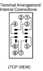
Got my relays in the mail today with mounts. See image of the top showing terminal placement and the other a copy from my old manual. I think I have marked the terminals on the copy correctly, would someone be kind enough to check please?
Attachments
Images (4)


Looking at the schematic and your relay I believe this would be right:

It's important for correct operation to note that while terminal 5 is contacting terminal 1, at the same time, terminal 6 is contacting terminal 2 in the relay's normally closed state.
When energized, terminal 5 is connected to terminal 3 and terminal 6 is connected to terminal 4 as shown on the diagram on the top of the relay housing:

There's not enough information provided to determine which relay terminals correspond to which screw terminals on the socket base. It may be best to confirm with a continuity check between each terminal socket slot and its corresponding screw terminal.
Attachments
Images (2)


Hey thanks for helping, I was a few terminals off. The socket base is numbered I marked each terminal worn a piece of tape, numbers on the socket are tiny. I will verify with an DVOM.
I am going to set up a simple oval for testing and notes, will report back.
Also will try out the article from Oct2007 CTT,
Attachments
Images (2)


I have run 2 trains on the same track about 30 years ago. If you are adept at soldering, you place a heavy duty diode inline with the loco center rail pickup inside the engine. And on the other engine, solder a heavy duty diode but with diode in the opposite polarity. Then on my ZW transformer, I placed the same diode on the voltage output of the left throttle (A) and placed a 2nd diode on the right throttle (D).
You then have 2 separate throttle controls, with left controlling one engine and right throttle controlling the other engine. No wiring blocks to worry about. The engines will not get full power because they are running with the diodes, but you do get totally separate control for 2 engines running at their own speed. Also need to turn off e- unit as I recall.
Carl J
Very clever approach to the two trains on one track question. Might have an issue with locos that don't like DC. Again, can't help but point out that today's approach using command control or dual capability wireless seems so much simpler.
Hi Bob,
Agree completely that modern wireless Command Control like Lionel introduced makes it very easy to get 2 trains ( and more!) on the same track working at different speeds without interfering with other locos/ speed direction or need of all the wiring blocks and relays. That is why I felt it was the “Holy Grail” to see Wireless command control come out.
Carl J
@Carl J posted:modern wireless Command Control like Lionel introduced makes it very easy to get 2 trains ( and more!) on the same track working at different speeds without interfering with other locos/ speed direction or need of all the wiring blocks and relays.
What is being done here with relays and whatnot is so much more than what Command Control can offer alone.
Command Control does not have this automatic signal control nor automatically keeps trains from colliding. Once this setup is up and running, no user input is required.
@Carl J posted:I have run 2 trains on the same track about 30 years ago. If you are adept at soldering, you place a heavy duty diode inline with the loco center rail pickup inside the engine. And on the other engine, solder a heavy duty diode but with diode in the opposite polarity. Then on my ZW transformer, I placed the same diode on the voltage output of the left throttle (A) and placed a 2nd diode on the right throttle (D).
You then have 2 separate throttle controls, with left controlling one engine and right throttle controlling the other engine. No wiring blocks to worry about. The engines will not get full power because they are running with the diodes, but you do get totally separate control for 2 engines running at their own speed. Also need to turn off e- unit as I recall.
Carl J
Can you run other trains without any problems and does the transformer diode affect the speed of other engines?
Hi Gene,
Your question on running other trains without diodes is an interesting one. Once you have added the diodes to both ZW throttles, trying to run any engines that do not have the diode installed, will mean that the unconverted engines put on the track will operate from both A and D throttles on the ZW. The unconverted engines without diodes do not run “separate” as will the engines with diodes installed. So you no longer have totally 2 separate engines running from 2 separate ZW throttles anymore. The ZW throttles with installed diodes will impact the top speed of both the engines with and without diodes. The speed will be slower overall with diodes installed on the ZW and engine. The system is now work with “pulsed DC” for the positive or negative part of the full AC wave form.
As I recall, the speed of the converted engines probably running 1/2 speed which was still plenty of power to go up my old layout grades.
Carl J
I have decided to go with Bob Walkers idea from CTT October 2007. It’s very straight to the point, not complicated, the necessary items will arrive next week.
This does not mean I am giving up on relay operations, will set up a large separate test oval and figure out how it’s done.
Hopefully will find the time to drive to Chantilly, never been to that show. Don’t get up to the area much any more for one simple reason, traffic. I remember as a child watching the trains run parallel to Washington Blvd in Arlington during the 60’s, later on when 66 opened up it all went down the sewer.
Parts arrived yesterday, I have attached a color copy of the article. I should have all the colors marked correctly, the lighter color appears to be grey, white is white, black should be the darker color and red/green appear to be tied in together.
Using a ZW transformer and looking at the drawing since it shows Red/Green and Black to 12V AC or DC I am confused as to placement of Blue, Red/Green and Black. Blue could go to A or D (throttles on transformer) Red/Green could go to B or C and Black (common) would go to U am I correct?
It might be easier to have a separate 12V AC power supply for Red/Green, Blue appears to be supplying power to all relays and track power/left/right section.
What do you think? I think I have it correct. Used to working with automobile schematics, parts manuals,
Attachments
Files (1)
Add Reply
Sign In To Reply
