
Last year I posted an animated circuit that can control a series of DZ-2500C switch machines with a momentary contact switch on a panel with indicators using a red and green LED.  For me, I have a complicated layout with a lot of switches so I cannot use the DZ-2501s button switches. Threse are just too big; resulting in a very large control panel. 

Thus, what I wanted was a single small circuit board that could control up to 20 DZ-2500Cs.  So, with the help of my son, a part time electrical engineer and his good friend, a full-time electrical engineer,  I have finally completed the design of both the schematic and circuit board. 

One of the key aspects of this design is that "one and only one" LED indicator is lit for each switch on the panel.  There are several circuits sold that do not do this; and even a free circuit design from DZ. with both of those circuits both LEDs are lit, even though the brighter one indicates switch position.

I wanted no extraneous lighted LEDs. My first task was to learn Eagle ( thanks SparkFun). That is the program I used to make this design. This is my very first, virginal circuit board coming from a former structural engineer with really bad grades in the common core electrical engineering courses..


I'm still a ways to go from having this made and tested and then very likely revised again.

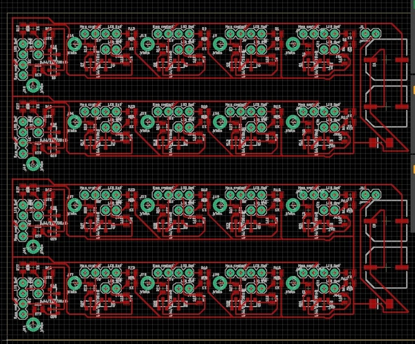
J1  is the 18vac power input; J2(labeled in wrong position) is below J3 both are wired to the red and greed LEDs on the panel. J4 is the contacts to the momentary contact switch on the panel next to the respective LEDs. Finally, J7 ( not sure what happened to the numbering since there is not J5 or J6) is connected to the WHITE wire coming from the DZ-2500C switch machine. 

The capacitors and 4 1/2 w resisters are shown along with mosfets Q1 and Q1; and the rectifier shown near J2.   

Once I get this completed and working, I will provide the completed circuit. I will be building a dozen or more for me.


Attachments

Images (1)
  • mceclip0
Last edited by AlanRail
Original Post

Replies sorted oldest to newest

Hi Alan - neat project!

You might be interested in an Arduino-based approach that I developed which uses bicolor LEDs to indicate DZ-2500 position. Each board could control a dozen switches.

I decided to use a microcontroller because I also needed to monitor and control a DZ-1000, and wanted some complex behaviors for yard switches. For regular DZ-2500 control the discrete approach is probably simpler.

PC  - I saw what you accomplished with the Arduino, but I'm barely above diodes! LOL

This circuit will let me develop fairly complex acrylic control panels using acrylic  inlays cut with my GlowForge laser cutter. Before I had the cutter, it was very slow drilling holes in the Plexiglas panels I have made.

Now I laser cut perfect holes for the LEDs and switches as well as intricate  track paths.

The black lines are cut and the green areas are engraved. I cut two copies one in say white acrylic and one in say orange acrylic. I then inlay the orange track paths into the white background.


Attachments

Images (1)
  • mceclip0

Alan,

Great project. I use Atlas switches and decided to go with an Arduino based system for a couple of reasons specific to the way the Atlas switches operate.

I really like your control panel. What program did you use to draw it?

I've been using CorelDraw for my control panel. After seeing yours, I'm going to have to work some more on mine. Here is a picture of what I have so far:

Train-largejpeg

The circles are where I'm going to put my LED's and toggles. I definitely need to add some labels. I also may try to round off the sharp angles.


Attachments

Images (1)
  • Train-largejpeg

Has anyone looked into using ESP8266 for wifi connection to arduino? ESP8266 monitors and controls switch and reports through wifi to arduino status. No wiring to each switch or block detection needed. Commands go from Arduino to esp8266 switch controller. Have the esp8266 operate off of local track power. This could save lots of wire on a layout. Just wondering if I am re-inventing the wheel.


Alan, do you have a schematic of the circuit you used with the DZ-2500 lights?  I happen to be building using the DZ-2500, and I'll be dispensing with the DZ-2501 buttons as well.  I'm thinking it would be cool with just a single bi-polar LED for red/green, saves panel space and still gets the point across.  Given the fact that sometimes the "thru" path is not the normal straight path, it should also have a polarity reversal capability, maybe a simple jumper.

It should be a reasonably simple job, I just haven't really looked at the signal from the switch machine yet to see what I might encounter.  From looking at the DZ-2501 button PCB, I'm assuming they do something similar to Fastrack switches and flip the polarity of the indicator voltage for switch position. 

I'm at the point where I have all the switches setting in position on the layout and I'm jockeying them around to make everything work, but soon I'll be wiring and wanting to know how I'm going to deal with the panel.

I will certainly keep that in mind once I have a finalized plan and have the track down.  I don't think it's a question of creating the .SVG file, it's an issue of creating one that looks good.

My layout is only 23 x 12, and I'm not going crazy with track, so I won't need that big a panel.  It's looking like I'll have less than a dozen total switches, about half of them concentrated in one area.  

I'm figuring on putting a temp panel just to get things working with a large connector feeding it.  That way I can pre-wire up the final panel without doing any external wiring and just drop it in, presuming I wire it correctly.   I would think a 20 x 11 panel would be more than sufficient to present a graphical representation of my layout.

Last edited by gunrunnerjohn

Alan, do you have a schematic of the circuit you used with the DZ-2500 lights?  I happen to be building using the DZ-2500, and I'll be dispensing with the DZ-2501 buttons as well.  I'm thinking it would be cool with just a single bi-polar LED for red/green, saves panel space and still gets the point across.  Given the fact that sometimes the "thru" path is not the normal straight path, it should also have a polarity reversal capability, maybe a simple jumper.

John, if you follow the link in my reply above, you'll see an installation I did with bicolor LEDs.

I get 1.1 V on the DZ-2500 white wire when straight and 5V when curved. That will read low and high on the Arduino (running at 5V of course) without any additional circuitry, and driving the white wire low toggles the switch.

Of course, with the Arduino approach, you can program as complex behavior for paths as you want. For example, I have a blinking indicator that alerts the operator that one or more of the yards is open, and the associated toggle will close off all the layout's yards.

Truthfully, I wasn't planning on going full blown automation, I'll be happy with just a nice panel and properly working lights for now.

If it's anything close to those values, it's a piece of cake to do a very simple circuit that will reliably light only one LED.  Adding a jumper would be easy.  I'm thinking along the lies of a Schmitt trigger 2-input XOR gate for each LED.  One input goes to a polarity jumper, the other to the white wire, the chip powered by a simple 5V supply.  Something like the SN74HCS86 would give me a four channel board.  I'd need an inverter to do the bi-polar LED.

I guess I need to put one of these on the bench and check what I get out.

Last edited by gunrunnerjohn

20  2500C s can be controlled on this board; 10 each per circuit.

Close up if the individual  circuit. 


Resistor values are show; Q1 and Q2  are Mosfet-NCH-AO3404A (2); Caps C1 and C2 are Rubycon 220uF; diode GS1GE; the connectors are J1 is the power  18vac; Connectors J2 and J3 go to the Red and Green LEDs on the panel; J4 goes to the momentary contact switch on the panel; finally J7 goes to the white wires of the specific DZ-2500Cs on the layout.

I plan to make about twenty of these.

at this point; I DON'T KNOW IF THIS WORKS SINCE I HAVE YET TO HAVE THE BOARD MADE AND POPULATED.


Alan

Attachments

Images (3)
  • mceclip0
  • mceclip1
  • mceclip2

Help me understand the value of this idea. Why would I want this instead of a) having switch controls along the fascia of the layout close to the switches, or b) controlling the switches through DCS using an AIU?

The reason I ask is that to me, the idea of having a "control panel" seems to me to defeat the purpose of having walk-around control, however that may be implemented. You have to go to the control panel to flip the switch(es) and you have all these long wire runs from the switches to the panel. 

I'm sure I've just missed the advantages of the control panel approach. Can someone set me straight?

Don 

Add Reply

Post

OGR Publishing, Inc., 1310 Eastside Centre Ct, Suite 6, Mountain Home, AR 72653
800-980-OGRR (6477)
www.ogaugerr.com

×
×
×
×
Link copied to your clipboard.
×
×