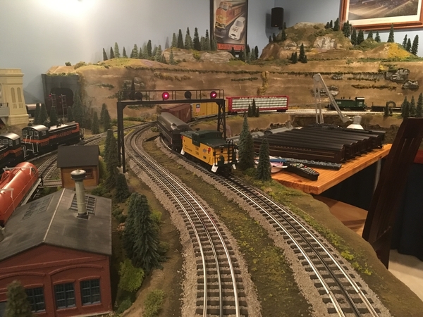
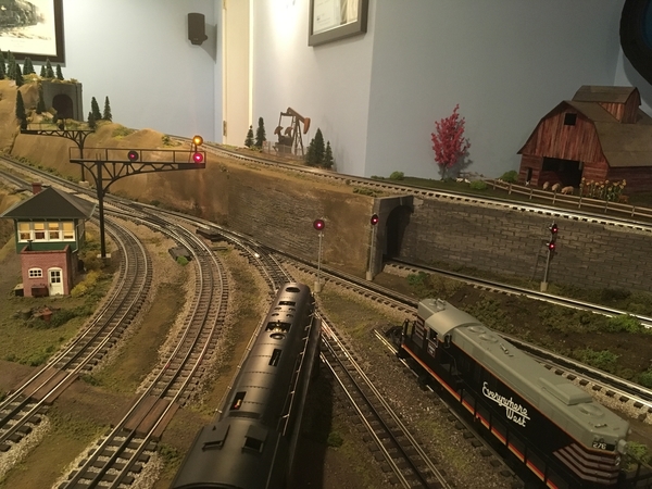
Here is my original layout I started back in 2006. It was built with the intention of being semi-portable and able to fit into a 10'x12' room. This layout had been assembled and disassembled through two different work relocation's.
Initial Construction
1st Relocation
2nd relocation
With the 2nd relocation gave me a basement, so I tore it down and started over with a couple of new design goals in mind
-Two main loops with o-72 radius as the minimum except for passing sidings
-Longer Trains
-No more drop in bridges to get access to the layout
-One loop with a grade and the other designed with out one for older LTI trains
-Storage of multiple trains for staging, but not hidden under the layout, but rather on shelves
-Trestle and water
-Mountain with hidden siding in mountain to hide train
-Some sort of icing facility
-All areas of layout with in a 3' reach to make scenery easier
Not much progress on the layout since last winter (summer came). Just completed most of my trestle, will not installed the X-braces until the scenery is complete.
Replies sorted oldest to newest


Thanks,
Alan
George
I have not put any pictures up recently. The layout is starting to look pretty respectable.
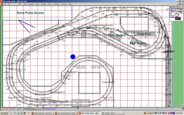
I started with the RR track plan below (24' x 15') back in Dec '10 and completed most of the bench work with tracks and switches wired (DCS and TMCC) by the end of Feb '11 ( also completed most of the scenery on the mountain).
The summer of '11 came with nothing else started until Dec'11, when I installed my trestle. Since then, I have put the remainder of my river in, created more pink snow around the entire house (from pink foam shaping), put down most of the ballast with a dirty wash, along with a skirt attached.
I think I have a little over 80% of my scenery roughed.
I used Patrick H's method of carving the foam and Dennis B. fake water approach (painted shower door glass) on the large part of the river.
Shown below are many of the various stages in the layouts construction to present day.
Mike
Attachments
Wow Mike absolutely superb craftsmanship, it looks awesome. Please keep us udated
with your progress. GREAT WORK!
Thanks, Alex
Mike I smell an OGR feature article,very Impressive! Keep us posted and may I say very inspriring work.
Mike
WOW! That is very good work. I will add this thread to ones I check out to steal...er I mean look at your work. Very nice!
Mike, I have no words! Too bad I live in Brazil so far, because I would like to see this wonderful person!
Congratulations, by design, the work, all fantastic!
Terrific layout, superb scenery design and workmanship.
thank you for all the photos
Mike,
Your layout looks great!
What did you use for the retailing wall in the water scene?
Dave
Mike I smell an OGR feature article,very Impressive! Keep us posted and may I say very inspriring work.
Well, I most certainly hope so! We're ready whenever Mike is ready (and willing)!
All
Thank for nice comments! I am a slow worker and wish I had more progress. I am very jealous at what others have completed on this forum in short order on several of the larger layouts.
David,
Regarding the wall, I cut the wood with a friends table saw to create the protruding edge of the wall and then glued them to masonite for the back edge. It looks convincing from the front, but added the top cap to conceal the top edge. When painted with several coats of spray gap filler, the vertical seam in the piling was created by scrolling an edge in to the filler.
Allan,
Not sure how much of the layout needs to be finished for an article (is it ever finished?), but would love to participate. I have a ton of images showing from the start to present day for my layout. Let me know.
Mike
Attachments
Uh, AWESOME!!! I really like the sea wall. If you get an article going for OGR please consider adding a how to on constructing the wall. What color did you use?
All
Thank for nice comments! I am a slow worker and wish I had more progress. I am very jealous at what others have completed on this forum in short order on several of the larger layouts
Peter,
Regarding the wall I cut wood with a friends table saw, glued them to masonite. When painted with several coats of spray gap filler, scrolled the vertical seam in the piling.
Allan,
Not sure how much of the layout needs to be finished for an article (is it ever finished?), but would love to participate. I have a ton of images showing from the start to present day for my layout. Let me know.
Mike
Mike....the layout is absolutely beautiful. You have done a wonderful job on all aspects of the scenery. Thanks for the update and pictures!!
Alan
Great Job! I only wish that mine will be half as nice when I get to start working on in real time!
Mike,
Your layout is looking great and you are doing an excellent job!
All the details are very nicely finished, but two items in particular caught my eye: the retaining wall by the lake, and the passenger platform between the tracks. Very well done!
Thank you for sharing.
Alex
The color used on the wall is camouflage brown from rust oleum
Top notch scenery work! It looks really good. Very creative with regards to the sea wall. ![]()
Mike,
Awesome layout! Thanks for the scenery update, fantastic! ![]()
Bruce
Mike,
Thanks for the tip! I plan on doing a small water scene, with retaining wall, in the very near future.
Dave
You are an artist!
- walt
Amidilly,
That really came out sweet!
Awesome vision and execution. That is inspirational. My favorite is the water. The ripples and the color are perfect. How did you do that, if I may ask? Then the trestle bridge. Your plan rocks too, with the seperate yard outside the main layout. I love it! I thank you for sharing your talent. Again, it is inspiring. Have fun, work at your own pace. I have built enough to know that everything takes time, especially when you expect the caliber of work you are after. Enjoy
Allan,
Not sure how much of the layout needs to be finished for an article (is it ever finished?), but would love to participate. I have a ton of images showing from the start to present day for my layout. Let me know.
Mike
Mike:
It certainly does not need to be completed (no layout is truly complete anyhow). Just needs to have enough done to provide images so about 15 or so can be used in the magazine.
And in the process of building your layout, you may employ some how-to techniques that might make for good articles over and above a layout feature (a step-by-step covering how to build a retaining wall, for example). We can always use more nicely illustrated how-tos features.
When you're ready, just contact me by phone or e-mail and I'll give you all the assistance I can.
Mike,
You have done fantastic and everything looks excellent. Great Job! ![]()
Your layout is incredible Mike!
What did you use for track...I see curved turnouts. Ross/Gargraves?
Yup I used Ross turn outs . I should have learned my lesson on my first layout in struggles of certain engines having electrical problems over curved turn outs. I learned the hard way that two of my articulated engines (lionel alleghaney and mth cab forward ) cannot make it physically through the o72/o96 turn out (the o72 route, it seems just add tadd too tight, I am not sure if it is what lionel would call o72). Not enough room on the layout to correct with a different switch. Try to avoid curved turn outs.
With the curved turnouts (we have a #8 curved on our layout) you have to wire in the closure rails (rails between the points and the frog) as alternate hot rails using a set of SPDT contacts on a tortoise switch motor. This will prevent stalling by locomotives with incompatible pickup roller spacing. If you're using Z-stuff switch motors, add the Z-stuff SPDT relay to the control. Also, make sure that both sets of stock rails are properly tied to common. This approach is also advisable on longer straight turnouts (#6, #8, #10) as well.
BTW, Mike, love the work on the layout. Looks great. Also like the sea wall construction technique -- first rate.
I finally have an update to post on my layout. I completed my dam for my river. When I was designing it, I was not thinking about how much water it would control but more of the general look. After looking at tons of pictures to model it after, I gave up and sketched my own design to build off of. I was excited to get started, only after it was built, did I realize that it can only regulate a bit more than a foot of water. The time a little project like this seems to take always seems more than it should.
The weathering leaves something to be desired, I tried dry brushing it. While it looks better than no weathering, I could be so much better. If any one had any recommendations for books on air brushing, I would like to read them.
Just now drawing my own plans for my icing station that will service 6 cars from between two tracks. I have been struggling on finding pictures to help me with this also. I would love to see any ones pictures to get some other ideas.
Mike
Attachments
Wow, the realism and detail is fantastic...thanks for sharing.
Mike,
Congrats on a fine job, I enjoyed the pictures very much! The lake is fantastic.
PCRR/Dave
Mike, I've heard of others using shower door glass for water, but I must say your rendition is the best I have ever seen. The color is just right. I am new to this so "that ain't sayin much". But wow, nice job!
Well done!
Peter
Mike,
That sheet pile wall came out great. The whole layout is awesome. I also like the railroadiana around the room.
Mike
You do some fine work. I enjoy the pictures. I hope I can copy Patrick's cutting method at least half as well as you have.
Larry
Simply amazing! Keep up the great work.
Your series of progressive shots as you progressed are most interesting. I also commend you on your impressive work.
I just want to add to the compliments you have received about your layout Mike. There is a lot of thought, creativity and attention to detail that went into this layout. The dam is an example of this.
Seeing the early photos of your benchwork and following the progress through your updates makes me appreciate all the work that has gone into this layout. Thanks for sharing.
Steve Tapper
Looks great! Please post more pictures. The wall and dam are very well done. Maybe a safety line and buoys behind the dam? rubber wine corks painted orange? 
Amazing; great craftsmanship. Love the lake & dam.
I love the guy in the inner tube below the bridge. the dam came out great. first I have seen anybody do that. a great idea. The design is great for the room. you can see all the angles and easy to access parts. it makes me think on how to design my 2 car garage layout because I have the center post. Super detail! thanks for sharing
Chris
The rock and water really came out fantastic Mike. Great Job
I am sure this old hat for many of you, but I was pretty excited on an area my wife and I completed over the last couple of weekends (been a while since any progress on layout). We picked up one of the tippi foam cutters to build walls with a brick pattern 24' long (3, 8' long sections ) for the back of layout. I think they came out really nice.
Staring with the pink foam Pattern
Giving them a texture with round handle dents and melting off the shark edges of bricks
Painting them dark grey and then working in rubbed light grey in certain areas for a more weathered look along with some green scenery grass
Area before the walls were placed
After installation
Attachments
Incredible. I just saw the whole thread for the first time. The water, dam, retaining wall - all of it top notch. I saw the demo on the tippi foam cutter - looks like it works better than advertised.
Thanks for sharing.
Mike....those walls look fantastic!
Alan
Looks Awesome Mike!
Hi Mike,
That looks fabulous, well done just like all of your work!!!!!!
Thanks,
Alex
Hey Mike,
Well done! The new walls look very real. The layout is surely coming along nicely. Thanks for posting.
Alex
Tippi foam cutter. going to watch it
Chris
I watched the tippi video also. wow easy to do with the right tool. I bought a foam factory straight bar one. but im getting that rounded one for doing this.! nice! spend 10cents rather than a fortune for these premade ones! and you take the round part and cut in different directions to get cut block or use a stiff metal handle spike brush to make cinder blocks ! wow. that easy. that video is great! watch
http://www.youtube.com/watch?v=aP3OGGmP1HE
Chris
can you show me more on this step?
"Giving them a texture with round handle dents"
I am sure this old hat for many of you, but I was pretty excited on an area my wife and I completed over the last couple of weekends (been a while since any progress on layout). We picked up one of the tippi foam cutters to build walls with a brick pattern 24' long (3, 8' long sections ) for the back of layout. I think they came out really nice.
Staring with the pink foam Pattern
Giving them a texture with round handle dents and melting off the shark edges of bricks. Painting them dark grey and then working in rubbed light grey in certain areas for a more weathered look along with some green scenery grass
Killer work all over!!
You are coming along just fine Mike. A really nice layout with many interesting features - you should be proud!
Thanks for the update Mike. Your walls as well as the layout look outstanding. Great work!
Thanks for nice comments all.
J Daddy
Here is an example before the sharp edges are taken off of the pattern (I just roughed in the pattern for a test piece
With tool there are many tips, I use the bigger loop shown below
I drag the loop centered in the mortar edge shown below.
My first pass shown above, is a little sloppy. Once you start doing it, you get feel for how fast to draq the tool across, not long enough, not enough gone, too slow, and you end you end up melting huge holes. I did a few more passes shown below. I think the key to this is that there is none of the original plane left of the foam, just texture.
Then I randomly hit the surface with round edge, I used my dry wall saw handle for this.
ONce a few random dents are placed, the results are shown below
Attachments
Not much progress on the layout since last winter (summer came). Just completed most of my trestle, will not installed the X-braces until the scenery is complete.
Layout Overview
http://ogaugerr.infopop.cc/gro...C321DB948D7F8925.jpg
Old layout with Trestle not cut out
http://ogaugerr.infopop.cc/gro...BDCCAF5C2D904634.jpg
Installing Bents
http://ogaugerr.infopop.cc/gro...4EE2773A536D5669.jpg
Installing Track
http://ogaugerr.infopop.cc/gro...41FA6B8AF9ACE7CA.jpg
Fun Picks after being complete
http://ogaugerr.infopop.cc/gro...35E4D2A31425A27D.jpg
http://ogaugerr.infopop.cc/gro...1CB529DC1F0E74A3.jpg
J daddy i like your wall also, different look.
i use ross switches and gar graves flex track.
Wow, am I glad I came to this sub-forum, today, for the first time! This whole thread is a gift of information, and the layout is spectacular ! You have created a very happy place which appears exactly suited to your smile. So, I am very happy for your success, Hump Yard Mike. Thanks for sharing the whole experience with us here. It is especially inspiring to see the obviously measured care and careful planning you exercised throughout.
FrankM.
I too just came across this thread. Mike I want to thank you for sharing the step by step process with both excellent prose and photographs.
I have very little experience with detailed scenery and this is exactly what I am looking for to help the STBL (Soon to be layout)
Love the detail and as Joe mentioned the railroadiana looks great.
all the best,
Paul
Fabulous job Mike! I love the lake and dam and the brick wall too. Turning into one heck of a layout.
Thanks for sharing. First time I saw this thread. I'll make sure to keep checking back.
Just completed my small town on my layout (well almost complete, still missing windows and interior lights). My layout theme was not really set up to have a down town, so I made it into one of my corners. Only room for one way streets in this town. A series of progress shots are shown below.
My wife Leah did both of the three story buildings and the red two story in the front row (Ameritown kits).
Hope to have the rest of the icing area completed soon.
Attachments
You do not mess around. Every post is a joy to see. Very inspiring. Nice work.
Very nice job Mike! You've done a magnificent job on this project.
Steve Tapper
It's been a while since you posted. Almost forgot how beautiful your layout is.
Mike,
Just curious, how do you get to these remote areas of the layout to work on them? The layout looks great.
Very great work! I especially like your "water." My only suggestion, with the greatest respect, remove the pictures off of the walls or much better put up a back-drop so that the visual integrity of your scene is not disrupted by a life-sized painting.
I have seen so many amazing layouts with absolutely outstanding scenery that was "tarnished" by objects in the background, i.e., destroying the visual integrity of the scenery.
Even a simple back-drop of pale blue if preferable to nothing.
REGARDLESS, your work is fantastic!
I would like to know what you do to the pink foam after you lay it out to make it look so realistic?
That corner looks great Mike. You and your wife did a fine job on those buildings.
Thanks for the update.
It would be very difficult to build this in the corner, so I actually built the entire module on my work bench and just placed it into the corner.
Regarding the sidewalks and street, I cut the sidewalk out of Masonite and painted them solid white, and then dusted them with brown and then grey paints, so they appear speckled(as described Dennis Brenan's hi rail book). To finish them up, they were scored to give them sidewalk relief cracks. These were then glued onto the painted pink foam.
The streets are plumbers putty tinted with black to give the light grey color.
MIKE REALLY NICE WORK HERE. THANKS FOR SHARING THE PHOTO'S
Hi Mike,
You and your wife, are turning out some really beautiful scenes, your entire layout is simply awesome and very well done. !!!
Hope too see you guys at York!!!!
Alex
You and I both are very fortunate to have wives that are into the hobby! My wife does awesome painting. I wish that I had the artist touch. Really great work!
super job on the ameritown buildings one of the best jobs i have seen
Mike.....really exceptional work! Well done.......I look forward to seeing more....
Peter
PS: That scene in your corner is very well done! Best of all it "hides" the corner on the wall. I always try to "round" where and when I can. Going for easy on the eye!
Mike,
Your work is first class! What a pleasure to follow along. I look forward to more updates.
Andy
Curious: What are the bricks made from?
John,
The bricks are carved in pink foam. If interest, earlier in this thread I show my technique
Thanks for the nice comments, it is really fun to look back at the older posts and see where you have come from.
For 2 years now I have been threatening to complete my icing facility. I finally settled on using the Altas O ice house and built my own double track icing platform from scratch (except the Shack). The reason for the two platforms is that the lower platform is used to unload ice for stocking the ice house and the upper platform would be used to load the cars, who knows if this is how they really did it.. The ice blocks move back and fourth by a motor, check it out on the utube link. With all of that, I just got it placed and landscaped last weekend. I am really pleased with how it came out.
https://www.youtube.com/watch?v=QH7aO7ts7ac&feature=youtu.be
The korber switch tower was also recently completed. My first building kit and first time using the brick motor. A rough interior was also constructed for it.
I tied the recently completed corner city scene into the rest of the layout with some additional landscaping and also completed a tunnel cutaway on the other side of the layout. The MOW crew came by to complete some switch point work and a frog build up repair.
After a 2 year search for the perfect piece of furniture that is short and not too overwhelming to the layout where I can just enjoy the trains, I found it last weekend at a 2nd hand store for next to nothing.
If I could figure out an industry scene by the river, I would be set
Attachments
Ice house looks good. I like the lighting on the platform.
Thanks for the update.
EXCELLENT TRACKWORK, KEEP IT UP! TURN THE COUCH AROUND TO ENJOY THE TRAINS!
I really like the workers on the platform shoveling the ice.
Mike....the layout is coming along nicely. World class work that you and your wife are doing! I like all of it and have really enjoyed following your updates...
Alan
"If I could figure out an industry scene by the river, I would be set" Give us a pix of the area in question, I'm sure with your talent and this group we can come up with something unique! ![]() Russ
Russ
The siding I need an industry for is shown below, starting off as 12" wide, widening to 15" and roughly 3' long. I plan to swap out the hellgate sometime in the future with lift bridges. Considering using a curved 072/54 switch off of the mainline lead for two stub ended tracks.
A river dredge and sand harvesting facility was a thought. I also have thought about some kind of crane that I might automate (something larger and more customized than the standard magnetic crane from lionel), not sure of the industry. I had also thought about a Griffin Rail Wheel manufacture, where raw materials could come off of a river barge.
Any ideas here would be appreciated
Attachments
Mike... beautiful pictures!! I like the idea of a barge and sand dredge...
Alan
"I like the idea of a barge and sand dredge..." I agree, some kind of barge, coal, scrap metal recycle maybe. An overhead dockside crane with clam shell bucket. Going to be a great scene whatever you do. Russ


FROM THE WEBMASTER
Outstanding job Mike! You did an awesome job with your water! Looks so realistic!![]()
Steve Tapper
Thanks for the suggestions all, please keep the ideas coming.
John,
Hope you had a good time with the train group.
Mike
Such a beautiful layout. I hope mine is half as nice as your layout.
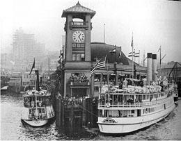
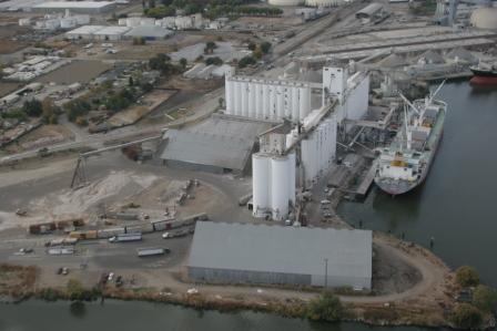
OK my suggestion is a grain elevator. I attached a few photo's. And you can do a barge or even a barge with a tug. Remember Lionel made o gauge tugs!
Attachments
oh, that looks great! That's the shower door glass water? and the sheet pile wall looks great. your layout is very detailed. wow. nice!
Thanks for the suggestions all, please keep the ideas coming.
John,
Hope you had a good time with the train group.
Mike
Another long duration (going back to March) since any forward progress has been made on the layout.
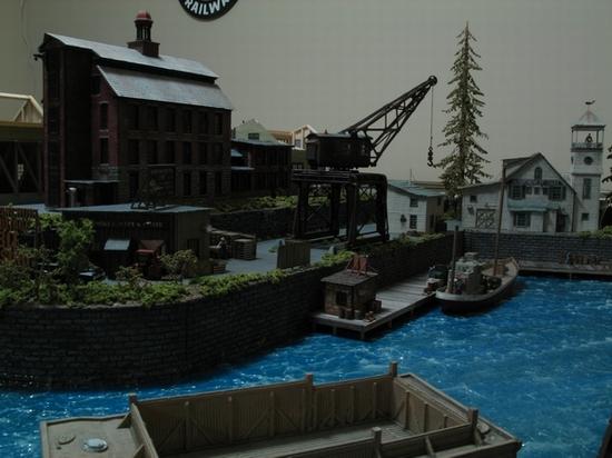
I made a decision to go with this Crow River Products Crane, purchased it last week. It looks very similar to what J Daddy posted (thank you for the pic).

In part of the decision process, i tried to build a rough scale model out of card board to see what it would like. I think it will come out looking really neat.
I hope to have some progress photos in coming weeks.
Mike
Attachments
Attachments
Very nice looking layout.
Excellent work, Mike!
Peter
Mike,
just read your post, simply amazing layout. Thank you so much for sharing your methods, especially the Tippi (Chris D., thank you for the link!). Had never heard of it and was always curious how the custom looking/fit walls were made. You and your wife should be very pleased with your work. I also like the sofa, very cool!
Completed a good part of the crane this weekend. Still have the boom and shrouds to complete, along with the entire trestle.
I tried pre-staining all the wood with alcohol and leather dye like I did on my previous icing facility project. This process warped most of the large pieces making it much more difficult to assemble. In the end, there are several wall not plumb, but it is passable for now.
Attachments
Its fun to look back through the progress and see what it used to look like and forget about the progress you have accomplished.
Attachments
Making more progress on the crane. I have upgraded it to move back and fourth a few inches adding wheels, rails and a motor.
The time in this project has suprised me, probably over 30 hours in this thing so far I am guessing at least another 4 are left. Still need to add stairs and crew changing station.


Attachments
Crane is finished. Upgraded to rails/wheels and motor to allow it to move (designed to be static). All lights are LED's. Need to work on harbor area next.
Video of crane:
https://www.youtube.com/watch?...amp;feature=youtu.be
Attachments
That is incredible! Great work.
Nice video.
Very nice. Excellent work. Nick
Excellent job Mike!
Dave
I am actually most impressed with the boom. That really tops it off, so to speak.
Looks great. Maybe you can help me with the steel mill painting.
Buzz
Great work Mike, the crane, like the rest of your layout, is fabulous. Thanks for taking us along on your layout journey. Keep up the good work. Rich
Amazing Progress mike!!!
All I can say is WOW!
Incredible work!
Keep the pics coming!
Peter
I agree with everyone else, Beautiful work. Nick
Attachments
Still lots left on the harbor scene. I have not decided between making my own barge from scratch or buying a kit. I also wanted to have a building to house a boiler for the crane, but do not have a clear direction on it. For now, harbor is done enough and moving onto the next project.
Here is a project my wife and I have been working on. I am running out of real estate, but still have a corner to use for a barn scene. We designed the barn from scratch based on a real picture from the internet. My wife cut, stained, assembled, and painted it from bass wood. With its proximity to the track, these animals will not be sleeping much. Hope to have some more progress of this area in coming weeks.
Mike
Attachments
Excellent job!!!!!!!!!!!!!!!!!![]()
Wow Mike, more great railroad modeling, I think from my view of your expertise the shadowy background is starting to reveal your able assistant, er girl Friday, no, master designer, no, acclaimed architect, no, Chief engineer, and tour de force wonder woman of the layout! Excellent work! You guys make quite the team. Great job and well done to both of you. Rich
Mike,
The crane makes an excellent addition to your layout. Great scene!
Andy
Sooooooo nice! Love it.
Looks just great! Did your wife use leather dye and isopropyl alcohol for the stain?
Just beautiful !
Wood was stained with the leather die and alcohol.
Mike
I completed it for less than $15 dollars total (wood and spray primer/scratch filler). Already had the ballast and paint colors on hand from other projects. Plenty of wood left over for the future service barge used for the dragline.
1st barge, made from scratch out of MDF and basswood.

Attachments
I completed it for less than $15 dollars total (wood and spray primer/scratch filler). Already had the ballast and paint colors on hand from other projects. Plenty of wood left over for the future service barge used for the dragline.
1st barge, made from scratch out of MDF and basswood.

Very Nice! I have to make one too!
Great work Mike, just beautiful. Rich
Its been a while since I have been able to show some progress, with the holidays and other house items that needed to be taken care. Last weekend, my wife and I had sometime to work on her barn scene some more and this weekend I cleaned up a few other areas on the layout.
Here is the barn scene, we decided to hold off on the roof and framing the window for now, to instead complete the scenery.
Here is a picture of the barge I was working on. I have so much more I would like to do with this scene in the future, including an additional dredge, more detailed tie on's for the barge and steam house for supply the crane
I weathered up my oil pumper with chalks and added some additional scenery around it to hide the base of the unit. I think it came it out really nice.
I also had a gas station area I was working on. I combined this with a track maintenance crew, who needed to remove a crossing to complete their work. I still need to find some cross bucks for it.
Attachments
Wow..
Sorry, I was late barging into this thread![]()
Great job, Mike!
Peter
Very nice scenery.
I think the fantastic work you do in the US, I go crazy here in Brazil!
Thank you for posting these pictures!
Great looking layout. Wonderful scenery.
Mike, it is looking very good! I like the barn a lot!
Great shots
Mike,
I had missed some of your expert work - everything is looking great! That crane is quite an accomplishment and looks fantastic. Hope to see more updates soon. Thank you for sharing.
Alex
Impressive!
Hump Yard Mike posted:I decided on building the barge myself instead of buying a kit.
I completed it for less than $15 dollars total (wood and spray primer/scratch filler). Already had the ballast and paint colors on hand from other projects. Plenty of wood left over for the future service barge used for the dragline.
1st barge, made from scratch out of MDF and basswood.
looks like the flood of Pittsburgh, 1936!
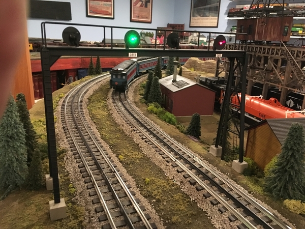
I have not had a layout update in a long while. I have been working on signalizing my layout. Just about complete with building the signals, where the signal bridges were kitbashed and modified with scratch built heads and the single mast signals and cants were all built from scratch.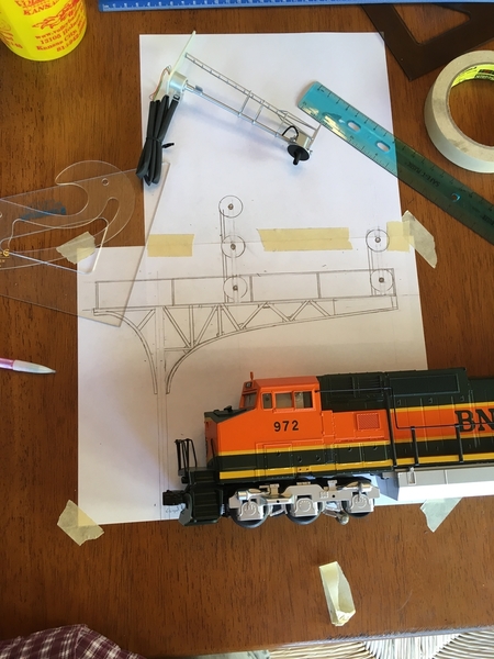
If interested in the construction process, the link is referenced below:
https://ogrforum.ogaugerr.com/...search-light-signals
Attachments
Fantastic work!
Peter
Thanks Peter!
Mike, what an outstanding layout you have going. Your work is tremendous, slow and easy is always a good thing. Thank you so much for sharing with us. I'm glad I had a few spare minutes to check the forum this morning. : ))
Mike
super nice work!
JEM and Rich,
thanks for nice comments.
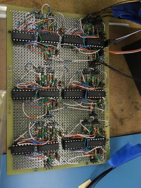
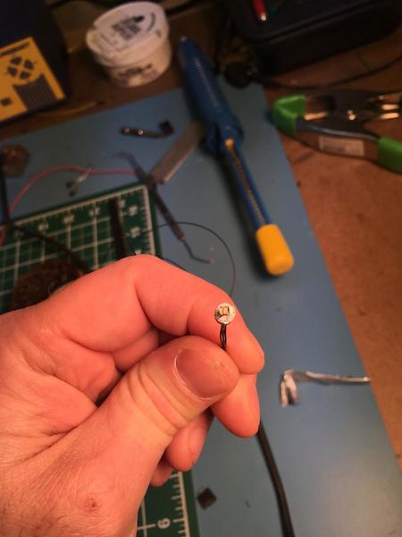
Still slow progress being made on the signal system. I built 18 of the 30 lamp drivers I need and mounted the little LED’s in one of my control points (only 9 heads). The picture showing the surface mount LEDs, the white grid lines are 1/2” for reference.
The cantilevers are toughest signals to wire and hide wires (16 wires in the mast of the 4 head cant ) but they are both done now. I really like how they look. Hopefully they will function as they should before spring time as there is a lot of work left on the signal logic.
Attachments
MIke,
Excellent work! Your layout continues to come along just fine. We enjoy your updates.
Alex
I want to learn how to build boards like that. I am always impressed as to what people do to make signals work. How did you acquire your knowledge to build boards? Looks great. I also like the simplicity of the around the room double main, with large switches.
Mike first off I want to tell you your work is outstanding. Next I have a question how close to the original track plan that you showed us on page one did you stay? Were there any changes? Because I remember you saying originally that you wanted one level Loop but from the pictures I don't see any. did you just go with grades or is there a loop in there that I'm missing? And again outstanding work!!!!!
Could you share a schematic for your signal system board so we can better understand the functions?
moed321 posted:I want to learn how to build boards like that. I am always impressed as to what people do to make signals work. How did you acquire your knowledge to build boards? Looks great. I also like the simplicity of the around the room double main, with large switches.
I can't speak for Mike, but I learned my basics on my childhood layouts and the rest trickled it's way into my mellon by chance.
I was surprised to ace the first test I took when applying for an assistants position and was soon hiring my own assistants. If you have a decent grasp of the basics, it's really just a jigsaw puzzle based on logic... fyi, they can usually be assembled in a number of ways too. I think that is were most folks balk in confusion. The same "look" and small size among modern components doesn't help put them at ease either, but I promise it isn't really as hard as it looks. Complicated? Sure..Hard? Not imo. It's still just "relays" (etc) in a new package
You might try a few Jameco kits as practice. They likely have quite a few breadboard projects that could be easily incorporated into a layout somewhere. (the board he uses is a solderable protyping board, breadboards are more of a temporary flavor, though they may be the final board used too). From there, it's all about the reference as to what each component can do... there are lots of options to choose from. Sometimes you build a ciruit to fit components, sometimes you fit componants into a ciruit. Refrence material for chips, etc. is an important part of making each next step easier. Short of schooling and daily exposure to it, just like with other train knowlwdge, you'll learn as you go.
Thanks for the comments and words of encouragement. I echo Adriatic's comment above on learning how to do this. I am not great at it, but still working on it. I will say having a decent soldering iron/ station and a solder sucker (for helping remove mistakes) were critical.
Kevster, the circuit is pretty simple, where there are two inputs, an H reference (for home block non-occupancy, one block past the signal) and a D (for distant block non-occupancy, 2nd block past the signal). If I had a chip burner, this could be greatly simplified to one chip, but I was not willing to purchase it for the few I needed made. My diagram is below. The H and D reference will be tied to a bigger logic circuit that ties the entire layout together, where relays help steer the from H and D block by switch indication to the proper signal head. I am also using an arduino to check the route exists (all switches are lined correctly) and the opposing signal at the control point for the same route is not cleared before allowing a better than red aspect. THe equations are shown on the bottom of the diagrams below. While the arduino logic is done and tested with an expanded shift register and the shown equations, the interface to the layout is not and is a work in progress. I will attach a picture of the logic diagram for this as well and progress on the board I am laying this out on. Each blue box on it represents a signal head and the colored arrows correspond to the H and D references on the signal driver diagram mentioned above. The west bound logic is close to being completed, where the east bound has not been started.
My original goal was to be able to show the wires for the H block (green wires) and the D block (orange wires) on this wiring board to guests and describe its functionality. As I have gotten more into this, I recognize this was not really practical and should have been done all in software, but I am committed now and staying the course. I am sure there are much easier ways to accomplish this, but this is where I am at.
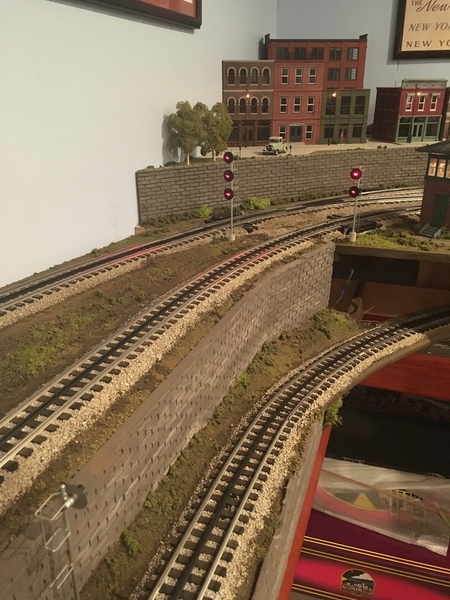
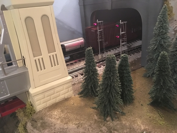
E-Unit, my track diagram is correct and my inside loop is on the same grade. It looks confusing because of the passing siding hidden on the inside loop goes under the outside loop grade. I included some RR track shots below, one with berms and one with out to show it. What is hard to see is the on wall storage sidings, as they are also two levels and on top of each other.


Attachments
Thanks
Ok. Now I understand . Thanks Mike looks like a lot of fun there. Enjoy..
Hump Yard Mike posted:Thanks for the comments and words of encouragement. I echo Adriatic's comment above on learning how to do this. I am not great at it, but still working on it. I will say having a decent soldering iron/ station and a solder sucker (for helping remove mistakes) were critical.
Kevster, the circuit is pretty simple, where there are two inputs, an H reference (for home block non-occupancy, one block past the signal) and a D (for distant block non-occupancy, 2nd block past the signal). If I had a chip burner, this could be greatly simplified to one chip, but I was not willing to purchase it for the few I needed made. My diagram is below. The H and D reference will be tied to a bigger logic circuit that ties the entire layout together, where relays help steer the from H and D block by switch indication to the proper signal head. I am also using an arduino to check the route exists (all switches are lined correctly) and the opposing signal at the control point for the same route is not cleared before allowing a better than red aspect. THe equations are shown on the bottom of the diagrams below. While the arduino logic is done and tested with an expanded shift register and the shown equations, the interface to the layout is not and is a work in progress. I will attach a picture of the logic diagram for this as well and progress on the board I am laying this out on. Each blue box on it represents a signal head and the colored arrows correspond to the H and D references on the signal driver diagram mentioned above. The west bound logic is close to being completed, where the east bound has not been started.
My original goal was to be able to show the wires for the H block (green wires) and the D block (orange wires) on this wiring board to guests and describe its functionality. As I have gotten more into this, I recognize this was not really practical and should have been done all in software, but I am committed now and staying the course. I am sure there are much easier ways to accomplish this, but this is where I am at.
E-Unit, my track diagram is correct and my inside loop is on the same grade. It looks confusing because of the passing siding hidden on the inside loop goes under the outside loop grade. I included some RR track shots below, one with berms and one with out to show it. What is hard to see is the on wall storage sidings, as they are also two levels and on top of each other.
Mike, I very like your layout that how will progress !
I'm planning my new layout and I would like know if could you send me the file the Rrtrack, because all the ideas help me in my project !
Thanks,
Leandro
I really like your layout. Good Job! I remember seeing your layout in OGR.
Paul,
Just now seeing your comment. Thanks for the compliment!
Able to complete my last signal driver boards. This was unique because I needed to add some additional functionality to put signals to red, if route was cleared in the opposite direction, to simulate tumble down at intermediates signals between control points.
I am finally able to at least light all the signals.
Next focus is to complete work on the logic board which coordinates block occupancy, switch position and east/west bound directions
Attachments
The signals are looking great, Mike! The signal driver board takes me back 40 years ago breadboarding circuits for a small company! The panel looks nice
Wow! Awesome layout!! Definitely following your topic. You have a youtube channel ?
Thanks for the comments.
Kon, I do not have a you tube channel. I may have to look into that.
Thanks!
mike
Awesome, Mike!
Peter
Mike,
That is a lot of hard work, and the results shows that it is well worth it. Well done.
Thanks for sharing!
Alex
Things are finally starting to come together and is getting exciting.
I made my first video describing my progress. The signal system will have route specific aspects and not allow opposing absolute signals to be lined into each other.
In the following video, I have my first signal cleared at a control point since starting this project, where the two blocks are being monitored past signal along with having the correct route lined for the specific route that the specific signal head is governing movement over. Also when the signal is cleared it is tumbling the intermediate signals past it to the next control point for the opposite direction of travel.
Mike
Attachments
There are a couple of other efforts on the layout to work on still, but the signal system was the last major effort on my list of goals when I started.
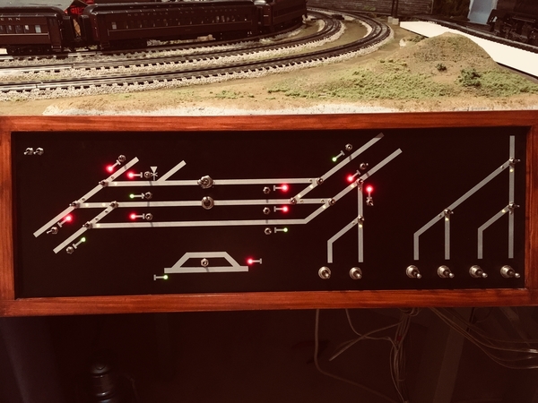
Signal system is finally in service and controlled through the panel below. The indications for the signals are red or green, with a green indicating a route lined and requested.
I have not worked on this every weekend, but definitely put a lot of time in the effort for almost two years. While the original goal was a prototypical signal system, that is quite challenging and I settled on a 3 aspect system (red, yellow and green) with an additional restrictive aspect in a few of the heads ( flashing red). The signal aspects are route specific. Signal routes from one control point cannot have the opposing routes lined into them. There is also tumbledown for the intermediate signals between control points (well kind of, I tumble the blocks on off the signal request at the control point. One thing this system does not do is monitor the track between signals (OS) at control points. Initially I thought this would not be a big deal, but seeing it now, i wish I would have planned this differently to do this.
I built all the signals myself out of brass stock, styrene and chicken wire, with exception of some of the signals bridge pieces I used from the plasticville model. Each signal head has three different color surface mount leds (red, yellow and green).
The signals operate off of track indication, switch positions, signal requests and a clearing bit I created at each signals which is done through an arduino (this logic bit looks for switch positions per route and opposing route clear bits). All of this logic then sends yellow, green, red or flashing red logic to clustered locations on the layout where there I used the standard 74 series logic chips to interpret the logic and drive the signals. Well over 500’ of additional cat 5 cable was used to wire the system.
I also have semaphores that operate all three aspects. I did not build the semaphores, they are lionel ones in which I gutted the old solenoid, and have the arduino controlling servos for their operation. Small bug here still in my code I am still working through which causes a little bit of a delay in their response.

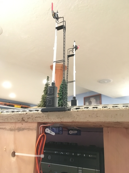 I am also still working through producing some better signs on the ROW.
I am very excited this is working now! This has been largest project effort on the layout to date.
I hope to post a video of the system in coming weeks.
Mike
Attachments
Looks Great. Looking forward to the 10th
Awesome work ! Nothing better than developing and making your own stuff !!
Very impressed with your abilities and your layout. Thanks for sharing so that so that I can use some of your ideas and methods for my layout someday.
Mike,
Your diligence and determination is second to none. Great work! Looking forward to the next video.
Dave
Thanks for the nice comments Steim. Happy to answer any additional questions.
Also appreciate your help on the cattle car.
Mike
Hump Yard Mike posted:
I am sure this old hat for many of you, but I was pretty excited on an area my wife and I completed over the last couple of weekends (been a while since any progress on layout). We picked up one of the tippi foam cutters to build walls with a brick pattern 24' long (3, 8' long sections ) for the back of layout. I think they came out really nice.
Staring with the pink foam Pattern
Giving them a texture with round handle dents and melting off the shark edges of bricks
Painting them dark grey and then working in rubbed light grey in certain areas for a more weathered look along with some green scenery grass
Area before the walls were placed
After installation
Hi Mike, I love your ideia !
I pretend to do this here in Brazil ! but I have a question !
What the size you used for each rock?
Thanks !
Hi Leandro,
I am not sure what you are asking? Are you looking for the size of the brick pattern?
Mike
Hump Yard Mike posted:Hi Leandro,
I am not sure what you are asking? Are you looking for the size of the brick pattern?
Mike
Mike, Yes !! Exactly this !
Thanks !
Leandro,
The vertical slots are roughly an inch a part and the horizontal slots are 5/16” of an inch apart. For long wall sections a long straight edge is important.
Thanks!
Mike


Attachments
Hump Yard Mike posted:Leandro,
The vertical slots are roughly an inch a part and the horizontal slots are 5/16” of an inch apart. For long wall sections a long straight edge is important.
Thanks!
Mike
Mike, Thank you !!!
Perfect !!
It was fun to visit your site again. I need to get going again. Thanks for all the past help, miss getting together.
tplee
Wow! this is so cool! ![]()


