Using the MTH DCS and TIU/AIUs for total layout control.
This control system design uses the MTH DCS system for total control of every aspect of the layout.
Two TIU units are available.
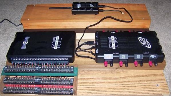
TIU#1 is used for engine control only. It is used exclusively with the DCS WIFI system. This system uses Passive DCS control. This technique avoids connecting power to the TIU#1 input channel. Only the TIU#1 output channel is connected to the track.
TIU#2 is used for control of turnouts, blocks and accessories. It is used exclusively with the DCS handheld remote. Two MTH AIUs are installed to completely control every turnout, block, signal and accessory on the layout. Individual pushbutton and toggle switch panels are also included to provide an alternate method of control which allows the operator to completely bypass the AIUs if desired.
DCS operation: Power to the track is provided by a Z4000. TIU AUX power is provided by an individual "Brick".
Turnout control: An auxiliary relay board interface allows the use of either miniature pushbuttons or the DCS handheld to control turnouts. The AIU internal relays do not conduct power to the turnouts but merely activate a separate relay coil.
Block control: An auxiliary relay board interface allows the use of either miniature toggle switches or the DCS handheld to control block power. The AIU controls power feeds to the track via the relay board. The AIU internal relays do not conduct power to the track but merely activate a separate relay coil. Note: The auxiliary relay contacts are rated at a minimum of 20 amperes.
All individual track feeds to the track have individual circuit breaker protection. A total of 10 blocks can be controlled by either the AIU or individual toggle switches. All turnouts and accessories are separately powered by transformers which also have individual output circuit breakers and fuses.
Emergency Trip Circuit: The Z4000 is used is with a dual 10 ampere circuit breaker box and a companion dual emergency E-Stop circuit. The E-Stop circuit is used with four E-Stop buttons located around the layout. Pressing any E-Stop trips all power to the track. A wireless controller also can be used to de-activate the power to the emergency "trip" circuit which then cuts power to the track.
Conventional operation: For conventional operation a separate Z4000 transformer is used with a switchover circuit that connects conventional power to the track. A separate twin channel 5 ampere circuit breaker and meter panel is used for conventional operation .
Dispatcher Panel: A separate Dispatcher Panel is used to provide status of all turnouts and block power. Color coded LEDs are mounted on a panel that shows the layout configuration.


