
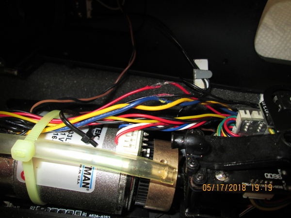
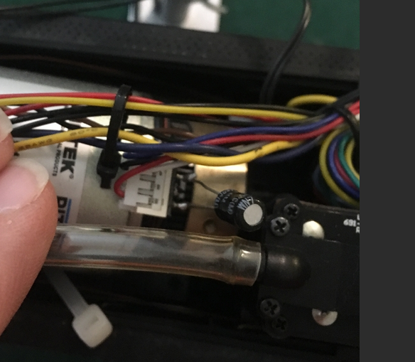
I have had this Vision Line Big Boy since July of 2014 and absolutely love it! Never had any issues until now, I was running it on a friends layout last weekend and we had a engine jump a switch so we immediately shut power to both loops of track. When power was reapplied to the track the locomotive refused to do anything. I would not respond to any command signal. I just got it back out at home and it worked just fine until it briefly lost power because of a loose wire on the track. Then it refused to again respond to any command signal. I came back a few hours later and again it worked just fine then with no power loss while stopped it freaked out again. I'm really not sure what is going on here, any ideas or suggestions to fix the issue will be appropriated! Attached is a video of what it does when power is applied and it freaks out.

Thanks,


Zachariah Hubl

Attachments

Videos (3)
KTDT1383[1]
LWAH8872[1]
RMKF3061[1]
Original Post

Replies sorted oldest to newest

ZHUBL  

The blinking headlight is a sign of bad antenna signal reception.

Try holding hand over both handrails if it works when in freak mode to all commands you have either a possible handrail grounded to boiler, or a wire has come loose inside the cab where it connects to end of handrail.

Another possibility is either the RCMC board and or the antenna board has failed.

Now when it freaks out will some commands work while others do not?

Try this test for me hold aux2 key for 3 seconds now try turning tender rear red lights on/off if like whistle it's acting same as mine did January of 2016.

Let me know results to above test suggestion's

cjack posted:

What is that second to last sentence..."if like whistle" mean?

I should have clarified that!

In video it shows the whistle not always responding to the command sent from cab-2 .

so if the tender lights or any command responds same way as the whistle command then symptoms are same and not just for the whistle command.

Hopefully I answered your question

StPaul posted:

ZHUBL  

The blinking headlight is a sign of bad antenna signal reception.

Try holding hand over both handrails if it works when in freak mode to all commands you have either a possible handrail grounded to boiler, or a wire has come loose inside the cab where it connects to end of handrail.

Another possibility is either the RCMC board and or the antenna board has failed.

Now when it freaks out will some commands work while others do not?

Try this test for me hold aux2 key for 3 seconds now try turning tender rear red lights on/off if like whistle it's acting same as mine did January of 2016.

Let me know results to above test suggestion's

I have had some ground issues before on an older engine. I don't think it is that but I'll double check tomorrow when I can and will let you know. I also feared a board might be fried…

thanks for the thoughts 

Alex Trains posted:

I am making a geuss but probably not correct, the track may have been dirty. Try cleaning the wheels and oiling the necessary parts. Also won't I would highly recommend is contacting Lionel and ask them, they are a great help

Not sure if the wheels are that dirty, they were pretty shiny last I checked, but I'll definitely double check. I was going to talk with Lionel but was too late by the time I got to it. 

Thanks for the suggestion 

There's a receiver board that slips into the RCMC driver board. It seems to me that this receiver board might have loosened up. You would have to take the shell off to see if it did. To take the shell of this engine there's two mounting screw's in the front and two in the back, once removed the top of the boiler will lift up. BUT you must be very careful there's many wires attached to the boiler, so don't lift it to high. If this board it loose, simply push it back down to reset it in place.

Alex

          SAMPLE PHOTO OF RECEIVER BOARD AND RCMC DRIVER BOARD

IMG_4012

Attachments

Images (1)
  • IMG_4012
Last edited by Alex M

Thank y'all for all of your ideas I think I have narrowed it down to that radio receiver board being losses or something shorts out after warming up. I tried it today, at first everything went just fine I shut off power to reprogram the locomotive to factory settings. when I reapplied power it did as shown in the videos. After sitting for a few hours it seamed to be just fine, did a few power cycles and still ran just fine but after about 10 min. I did another power cycle and again back to the original issue. With any luck something is just loose, worse case it'll have a long cold trip from Kansas to NC for Lionel to take a look at it.

Thanks Again!

I feel your pain; I have a Big Boy that I bought in 2015 with no issues except meager blow down.  It is good to know that the main board is below the blow down fill as mentioned by JOJO (good to know so as not to overfill that).

Have you now run the Big Boy and tested it yourself on your layout?

I use a ZWL to power my layout which is supposed to have adequate circuit breaker protection for the Legacys.

Are there any thoughts from the forum on the possible power surge?? from the incident in your original post? 

RickM46 posted:

I feel your pain; I have a Big Boy that I bought in 2015 with no issues except meager blow down.  It is good to know that the main board is below the blow down fill as mentioned by JOJO (good to know so as not to overfill that).

Have you now run the Big Boy and tested it yourself on your layout?

I use a ZWL to power my layout which is supposed to have adequate circuit breaker protection for the Legacys.

Are there any thoughts from the forum on the possible power surge?? from the incident in your original post? 

Unfortunately I don't have my own full layout running yet just that small test track shown in the videos above. Between life I haven't had a chance to fully test the locomotive but a quick test last night showed it was working good.

I'm personally thinking the reason for the short has something to do with MTH. The layout I was running it on when the incident occurred is almost always MTH engines. So it's powered by a Z4000 and a TIU along with legacy. I'm thinking seeing as there was no direct short on the track but power was abruptly shut off either the Z4000 with a normal sine wave compared to all other transformers with a modified one had some sort of surge. Or a DCS signal piggybacking on the power screwed with something. But there's no exact way of knowing. 

On another note, from what I hear the ZW-L is a very good transformer and is what I plan to use for a power source when I get my layout going. 

ATSF Doug posted:

Hey Zach, too bad that 4014 is acting up, I was wondering if it would be able to squeeze through the O-63's on my new layout.  Hopefully it will be working well by the time you get up here to see the layout.

The locomotive will take O54 believe it or not.  But the tender is very unhappy to take anything below O72 (I have a friend that has run his on O63, slowly.).  So just like the prototype, the tender is the real limiting factor when it comes to track radius.

Ok new issue, I finally had time to throw the engine on the track and test it. everything seamed to be fine bu as soon as I hit Speed step 23 on the legacy remote the engine slows and acts funny. Almost as if instead of the two engines operating separately it sounds like their running at exactly the same pace. I have tried to reprogram it with no luck, I am thinking it is the RCMC again but they just replaced that! I will try to have a video up soon (May have to be in bits due to the upload file size limit)

ZHUBL, in last video your BB is working fine as speed picks up the chuff sounds combine as one this is normal.

my BB works same as yours, as a heads up if you have the small funnel that Lionel includes with some of later steam engines use it to add smoke fluid into blow down fill hole it will eliminate the fluid possibly getting onto the rcmc board below.

also make video longer and then upload it to you tube and then embed the video into your post can be longer video that way.


Last edited by StPaul
zhubl posted:

Ok new issue, I finally had time to throw the engine on the track and test it. everything seamed to be fine bu as soon as I hit Speed step 23 on the legacy remote the engine slows and acts funny. Almost as if instead of the two engines operating separately it sounds like their running at exactly the same pace. I have tried to reprogram it with no luck, I am thinking it is the RCMC again but they just replaced that! I will try to have a video up soon (May have to be in bits due to the upload file size limit)

I had a similar problem with my brand new VL Big Boy Christmas 2014. I described the problem to Lionel as follows - "As soon as the work lights go off, at around speed setting 21, the engine decreases in actual speed but the engine sound speeds up. This continues through speed 36 or so, and then the engine accelerates and its motion catches up with the sound."

I called Lionel, and their service rep had me conduct some tests, but in the end determined that I had to send the Big Boy to them for service. I did, and received it back in four weeks. I have run it on a regular basis since then, and have had no further issues with it.

Alex

Ingeniero No1 posted:
zhubl posted:

Ok new issue, I finally had time to throw the engine on the track and test it. everything seamed to be fine bu as soon as I hit Speed step 23 on the legacy remote the engine slows and acts funny. Almost as if instead of the two engines operating separately it sounds like their running at exactly the same pace. I have tried to reprogram it with no luck, I am thinking it is the RCMC again but they just replaced that! I will try to have a video up soon (May have to be in bits due to the upload file size limit)

I had a similar problem with my brand new VL Big Boy Christmas 2014. I described the problem to Lionel as follows - "As soon as the work lights go off, at around speed setting 21, the engine decreases in actual speed but the engine sound speeds up. This continues through speed 36 or so, and then the engine accelerates and its motion catches up with the sound."

I called Lionel, and their service rep had me conduct some tests, but in the end determined that I had to send the Big Boy to them for service. I did, and received it back in four weeks. I have run it on a regular basis since then, and have had no further issues with it.

Alex

Alex,

That is Exactly what it is doing! It sucks to hear that it had to go back to lionel, especially since I JUST had it there for another reason. By chance to you remember what they replaced?


Zachariah 

Last edited by zhubl

Zachariah,

Unfortunately, no; I do not remember what/if they told me they had replaced. I just looked at their emails pertaining to this issue, and they did keep me abreast of their progress and shipping, but a reason for the problem was not included in their emails. If I find the packing list, I'll let you know.

Good luck!

Alex

RickM46 posted:

Alex and Zachariah,  did you ever find out what the fix was for this condition on your Big Boy:

"As soon as the work lights go off, at around speed setting 21, the engine decreases in actual speed but the engine sound speeds up. This continues through speed 36 or so, and then the engine accelerates and its motion catches up with the sound."

I remember the Lionel service tech left a note on what he had to do. I’ll see if I can find it but it must me some fluke with certain boards. Litterly I think they just added a capacitor in it. Like I said I’ll see if I can find the note 

Wow, great help from the forum.  Thanks to Sinclair and Zachariah!!  Looks like there are 2 possible solutions:

Sinclair had a cap - part 691CAP4750 - installed on the motor.  Looks like the small black rectangle on the top of his motor picture.  See part diagram https://www.lionelsupport.com/...ca-b305-36d7636e967e

Zachariah had the following done as documented in his service receipt by the tech: 'Install capacitor (no part number) on encoder board which solved the speed step issues along with replacing broken valve gear assembly.  Plus replaced defective motor driver board on tender.'  Parts were: 691MDR1C01 - Motor Driver/Light Controller/Tender Coal Load and 6101434157 - Valve Gear Assembly/LH/Front/Vision Big Boy.

Sinclair, did you do the install of the cap?  Did it have to be soldered in place?

Alex, did you ever find the service receipt?

I appreciate the effort from you two in helping me out.  Now, I have to figure out next steps.

Last edited by RickM46

The story with my VLBB is I finally got the 1st stage of my layout done, a loop of O72 track so I could run this loco.  So I put it on the track and got lights and sounds and nothing else.  After contacting Lionel I was told they aren't taking out of warranty repairs (This was early Q4 of last year.), but a Lionel Service Center should be able to help me.  I emailed back that I didn't have any near me, and that I wasn't afraid to the the work myself.  So one of their guys took the time over the next few days to email back and forth with me to troubleshoot and decided the problem was the RCMC.  I sent them that board and they tested it.  It was bad so I bought a replacement.  Once installed the locomotive ran again, but did that funny thing with the speed .  More emails and they sent me the cap.  I then soldered it on and now it runs nice and smooth again.  I was really happy with their help taking the time to let me fix it over email.  But then I am a mechanical engineer and don't fear digging into things.

Sinclair, thanks a bunch for the quick reply.  I am no stranger to hand tools and solder.  I just had my RCMC board replaced by one of the best Lionel techs for a Big Boy.  I don't know if the cap is already on my motor.  I will drop him a line and see if he remembers seeing the cap there.  I saw where the cap is cheap - $3.50 - and wouldn't mind putting on one myself.  Do you remember how many leads come out of the cap and where to solder them??   Thanks a bunch.


It's a 4.7uf 50V bi-polar capacitor, a cheap place to get it is Digikey as Lionel will have expensive shipping.

Nichicon CAP ALUM 4.7UF 20% 50V RADIAL, 28 cents each.  Shipping for small orders from Digikey is only around $3, and the ship very fast, usually in a couple of days you'll have your parts.  You can have a few for around $5 total.

Attachments

Images (1)
  • mceclip0

Gentlemen,  I am about to take the shell off the Big Boy to see if there is a CAP on the motor.  I know there are 4 screws and where they are at (just forward of the cab and in deep inserts and 2 under the front driver).  I have a foam cradle to work from.  I am thinking that there must be a process to do this.  Maybe turn the loco upside down in the cradle to remove the screws and then??????  How to get it out of the cradle to right side up????  Any pointers would help.  I have seen many threads on how easy this is but no detail.

The hand rails and cab light plug into a board screwed to the top boiler shell.  You'll need to disconnect the wires from that board to the boards on the main frame.  There are also wires towards the front of the boiler for marker lights you'll need to be mindful of.  Hence why you move the top slowly.

As for where the cap wires go, I'll have to look.  And there are only two.

I have successfully separated the shell without breaking anything; once you find the right 4 screws it separates easily with no force (mistakenly took out the wrong screw under the cab).  The toughest part was putting the loco back on its wheels and keeping the boiler in place; big danger to the front boiler number board lights and marker lights and wire hand rails due to my hand getting too close to them - luckily they suffered no damage.  I have it lying beside the bottom with the wire connectors to the front of the boiler marker lights still connected but have that front close enough to the bottom so no stress on them.  Lots of slack in the rear cab lights due to the wires sticky stanchion being unstuck.   I am working on adjusting my camera to send a photo. 

The top of the motor does not have the round (I thought it was rectangular) cap.  Now, here is where maybe I can get some directions on how to install it once I get the cap.  Finally figured out that cap really stands for capacitor - feel like Homer Simpson - DOH!

Last edited by RickM46

Well, chalk up the next picture to Divine Providence.  Upon inspecting the wiring going from the rear of the motor forward, I found a number of wires that had their insulation fried by heat and then fused to one another.  The top red wire was fused to the black wire just below it and then that to the blue wire below the black wire.  When I separated them, the top red wire lost its insulation for an inch.  I also discovered a red and black wire attached to the 4 wire white plug at the top of the motor looking stressed by heat.  I am thinking that at one time those wires were located too close to the smoke unit.  Any suggestions for repairing the exposed spot on the red wire? 

I also am open to any advice on attaching the cap when it arrives.

Attachments

Images (1)
  • blobid0
Last edited by RickM46
gunrunnerjohn posted:

Obviously, the simple method of fixing a wire is just splicing in a fresh piece of wire.  Using heatshrink of the correct size, you can make it pretty slim and it shouldn't be an issue.

Thanks GRJ, I am gearing up for the cap as well.  I have a Hakko FX888D-23BY on its way with heat sinks and multiple tips.  I also have electrical 60/40 rosin core solder, heat shrink tubing of many sizes, lots of 18 Gauge red and black wire.

RickM46 posted:

Well, chalk up the next picture to Divine Providence.  Upon inspecting the wiring going from the rear of the motor forward, I found a number of wires that had their insulation fried by heat and then fused to one another.  The top red wire was fused to the black wire just below it and then that to the blue wire below the black wire.  When I separated them, the top red wire lost its insulation for an inch.  I also discovered a red and black wire attached to the 4 wire white plug at the top of the motor looking stressed by heat.  I am thinking that at one time those wires were located too close to the smoke unit.  Any suggestions for repairing the exposed spot on the red wire? 

I also am open to any advice on attaching the cap when it arrives.

IMG_0201

That usually is caused by having one roller power pickup like in the front on one voltage or ground and the other pickup in the rear on a different voltage. Then a huge current flows between the rollers which are connected together by a red wire which melts it’s self and anything it touches.

RickM46 posted:

Chuck, thanks for the input!  Maybe my track voltages aren't what they should be; makes me want to test each segment with a meter.  I have a ZWL where I set the voltage lever to 17 volts.  Lost the picture - re-inserted it again.

Sometimes it's a derailment, sometimes between a non powered block with a potential load parked on it and across to a powered block.

I did have a wire meltdown in a Genset due to one side (the powered side) of the smoke resistor shorted to ground. I had to replace the wires on three smoke units and another harness. All melted together. I did find out that Lionel parts search for "harness" and similar terms allowed me to construct what I needed by buying appropriate parts. There were and are few harnesses listed with engines. I was avoiding crimping up my own harness, but as GRJ points out, it's a lot cheaper to crimp.

Chuck, thanks for the info!  I am awaiting some new soldering gear, wire strippers, wire, and finally the capacitor.  I have to admit, after looking at the interior, Lionel engineers did a great job of routing and placement of the bunches of components.  I am leaving the electrical plugs untouched - tried to unplug a few with my finger tips but they wouldn't budge; still plenty of room to work with the boiler off to the side.

sinclair posted:

Actually, the boiler is still off of my BB as I was planning to work on the smoke units, but life got in the way.  I can take detailed photos of where the cap goes, but not until late Saturday or Sunday, if you can wait.  I just soldered the cap in place without removing anything from the chassis.

Sinclair, thanks a bunch!!  I am awaiting the cap and other soldering gear so take your time.  Pictures would be great.

MartyE, this forum sure made my repair easier and I was greatly helped by the pictures on this thread  https://ogrforum.ogaugerr.com/...boy-tons-of-pictures from Alex M. 

I am no master of soldering but have been practicing with the Hakko 888D; I found that using it and a chisel tip and 750F and heat sinks that tinning a 18G wire goes quite easy; also studied many YouTube videos on soldering.  In addition, I have practiced with my Weller WLC100 at knob position 4.  However, when the caps arrive, I will definitely need some advice with soldering that.

I recommend you drop the temperature to 650F on your soldering iron, and if you do any PCB soldering, I'd be at 550-600 maximum.  I also use the needle-point tip for most of my work, especially PCB work.  Truthfully, I haven't gotten out the extra handle with the chisel tip in months, never needed it.  The beauty of a temperature controlled soldering iron is it maintains the temperature no matter what the load until you exceed the heat that the 70W element can deliver.  Soldering #18 wire with mine at 650F with the needle point tip is no problem at all.  For really heavy wire, I get out the Weller soldering gun.

Sorry, I got busy trying to finish a DCC install.  But I did take a photo.

IMG_3390

It goes on the back side of the PCBA at the connector location, the leads go on the red and black wires.

I did tin the leads first.  Yes a small tip on your iron.  Lower temp.  having a helping hand helped a lot so the cap didn't move on me as I was soldering.

As for the cap, from what Lionel told me it acts like a filter and smooths out whatever needs smoothing so that the speed is nice and steady.

Attachments

Images (1)
  • IMG_3390
RickM46 posted:

GRJ, thanks, that info is what I exactly needed for the job on the Big Boy.  I am making notes.  When I solder the capacitor, what temp range do you recommend?  I have the Hakko 888D and have electrical 60/40 .062" rosin core solder.  Should I tin the ends of the capacitor before soldering?

.062" solder?   First thing I'd recommend is getting a finer gauge of solder!   I use .031" for general use, and .020" for PCB work.  I don't even have anything the size of .062", that has to look like a train tunnel.  Yes, you should always tin any bare lead, makes the job go smoother.

Here's your solder...

Attachments

Images (1)
  • mceclip0

Thanks Sinclair!!  Just some questions per the pictures below, will appreciate your patience:

1.  The capacitor's 2 leads have one that is shorter than the other; does it matter which goes to the red and black?  

2.  When you mention the backside of the PCBA board, are you referring to the solder nubs forward of the white plug that attaches to a board (see the first picture below, where from the right side of the white plug, there are wires red, white, black, blue and corresponding solder nubs on the forward side of the board)? 

3.  I take it you soldered the cap leads to the red and black solder nubs on the forward side of the board? 

4.  At what temp was your iron set to do the soldering? 

5. What size solder did you use?

6.  On the second picture below, it looks like the cap is sitting on the motor and rearward of the PCBA board.  Is that where you finally located the cap?

Attachments

Images (1)
  • blobid1
gunrunnerjohn posted:

Just curious, why not cut the leads shorter, or at least slip some insulation on them.  I'd be somewhat concerned about it shorting to the flywheel.

Because the Lionel photo of the motor didn't show any tubing or shorter leads, so it didn't even occur to me (I'm new at this compared to you after all, still learning.).

RickM46 posted:

Thanks Sinclair!!  Just some questions per the pictures below, will appreciate your patience:

1.  The capacitor's 2 leads have one that is shorter than the other; does it matter which goes to the red and black?  

No, if you got the cap from Lionel it doesn't matter which lead goes where.

2.  When you mention the backside of the PCBA board, are you referring to the solder nubs forward of the white plug that attaches to a board (see the first picture below, where from the right side of the white plug, there are wires red, white, black, blue and corresponding solder nubs on the forward side of the board)? 

Yes.

3.  I take it you soldered the cap leads to the red and black solder nubs on the forward side of the board? 

Yes.

4.  At what temp was your iron set to do the soldering? 

Will have to look when I get home.

5. What size solder did you use?

Will have to look when I get home.

6.  On the second picture below, it looks like the cap is sitting on the motor and rearward of the PCBA board.  Is that where you finally located the cap?

I took the photo Saturday night, and it hasn't moved.  I'm sure when I go to put the shell back on I'll probably bend it out of the way and use insulation of some kind.  Like John pointed out, I failed to put heat shrink on it, so I'll probably apply some Kapton tape.


The Lionel caps showed up today and their leads are only 3/8 inch long - not too long for the spot where they have to be soldered to the PCBA nubs; definitely will take 3 hands.  I see why Sinclair located the cap where he did; it is elevated enough to easily miss the flywheel.  Here they are:

Gunrunnerjohn, you mentioned these alternative caps below; would you happen to have any and the lengths of their leads? 

It's a 4.7uf 50V bi-polar capacitor, a cheap place to get it is Digikey as Lionel will have expensive shipping.  Nichicon CAP ALUM 4.7UF 20% 50V RADIAL, 28 cents each.  Shipping for small orders from Digikey is only around $3, and the ship very fast, usually in a couple of days you'll have your parts.  You can have a few for around $5 total.


Attachments

Images (1)
  • blobid0
RickM46 posted:

Gunrunnerjohn, you mentioned these alternative caps below; would you happen to have any and the lengths of their leads? 

It's a 4.7uf 50V bi-polar capacitor, a cheap place to get it is Digikey as Lionel will have expensive shipping.  Nichicon CAP ALUM 4.7UF 20% 50V RADIAL, 28 cents each.  Shipping for small orders from Digikey is only around $3, and the ship very fast, usually in a couple of days you'll have your parts.  You can have a few for around $5 total.

The beauty of Digikey is they have real parts with real specifications.  For the cap above, for instance, they specify the lead lengths.

Attachments

Images (1)
  • mceclip0

Figured out how to have an extra hand for the soldering of the cap to the solder nubs at the top of the board.  Taped the cap to the end of the alligator clip and positioned the ends on the nubs; put some yellow heat shrink over the nubs that I didn't want to touch; took the top of the blow down funnel off to give me more room; needed the QuadHands Helping Hands to help since I don't have the hands of a brain surgeon.  Now I am just waiting on the right size solder and solder tips to show up.  You can just barely see a cap lead tip resting on one of the nubs.  I will do the outside nub first to hold the cap in place.  See pictures.

Attachments

Images (2)
  • blobid0
  • blobid1
Last edited by RickM46

I used .032" diameter 60/40 (3.3% flux) solder.  I had a 1.2 mm bevel point tip in my soldering iron, and it is currently set to 250 degrees C (480 F).  Don't know how accurate it is as it's a used unit I got for free and have no clue when it was last calibrated.  But I just did a lot of soldering with it this last weekend doing the before mentioned DCC install.

sinclair posted:

I used .032" diameter 60/40 (3.3% flux) solder.  I had a 1.2 mm bevel point tip in my soldering iron, and it is currently set to 250 degrees C (480 F).  Don't know how accurate it is as it's a used unit I got for free and have no clue when it was last calibrated.  But I just did a lot of soldering with it this last weekend doing the before mentioned DCC install.

Thanks Sinclair, you have helped out immensely!

I bought the Chinese clone of the Hakko FG-100 calibrator, it's worked quite well for me.  The genuine article goes for $250 or so, but the clone set me back $20.  I've tested it's accuracy with my Fluke temperature probe, and it's quite accurate. It's a mystery how Hakko can charge $100 for the iron and $250 for this little calibrator!  The guts of the calibrator are very simple, it's just a K-Type thermocouple with a circuit to read the temperature and a feature to hold the max temperature.  Big deal!

There are several clones listed on eBay, here's one: eBay 122561208159, it's $20.  You can also just search for Hakko FG-100 and find several more.


Attachments

Images (1)
  • mceclip0

Got the capacitor installed and now the Big Boy runs smooth thru all speed steps - go figure.  Many thanks to Gunrunnerjohn, CJack, Zachariah, Alex, StPaul, Sinclair for the info to do the job.  I soldered two 2 inch lengths of 20g wire to nubs 1 (red) and 3 (black) on the board and then the capacitor to those wires.  I located the finished assembly rearward over the motor.  I had to re route the collection or wires going forward over the motor to the left side of the motor.

Since I have never soldered before, I shielded the nubs on the board with heat shrink tubing and put a strip of tape just below the nubs to catch any debris and protect the board.  I did a bit of practicing on 20g wire with .8mm rosin core solder and a Hakko FX888D and a watched a few Youtube videos.  I found after a bit of experimentation the best temp was 585F, tinning the wire AND the solder nubs on the board AND using a long needle soldering tip with tinning worked the best.  Regarding soldering, I have the mind of an artist and the hands of a butcher; the result wasn't pretty but it worked.  If I ever take the shell off again, I might redo some of it.

Thanks for the encouragement gents; I spent nearly 2 hours soldering practice wire and gradually walked the temp up from 550F to 585F to arrive at the best temp.  At that temp, tinning the wire and the tip worked fine.  Attaching the wire to the dry nubs on the board did not work; finally got the idea to tin the nubs too.  Would not have gotten very far without the forum, Hakko, long needle point tip, heat sinks, Youtube, and the QuadHands gizmo.

Last edited by RickM46

Add Reply

Post

OGR Publishing, Inc., 1310 Eastside Centre Ct, Suite 6, Mountain Home, AR 72653
800-980-OGRR (6477)
www.ogaugerr.com

×
×
×
×
Link copied to your clipboard.
×
×