Dear Gentlemen and ladies


Here is my next project and I am looking for guidance.  I have already spoke to rtr12 off the forum but I want to bring into the forum. He has been very helpful with his suggestions and comments but I need the broad analyses of what the new project will in tail. See below Reader Digest Condensed version of what I am trying to do:


Since my layout is carpet layout and adding these meter would add to the boxes and wiring on the floor, I was think of consolidating some of these electronic boxes into one bigger project box and eliminate some of the wiring and project boxes. Here is my thinking on the voltage and amp meter project. Building voltage and amp meter system to incorporate the TVS and fast acting circuit breakers into the system.  Since I am building this new project box I might as well add the bell and horn switch into the system to the Postwar ZW only. Here are my transformer list, ZW-C volt and amp meter only. postwar ZW placing the Ms. Beats and GRJ design for the horn and bell with the voltage and amp meter, 2 KW, MTH 4000 voltage and amp only and a 1033 with everything. I now think maybe this system should be a control panel type instead of a project box design. Have one large control panel where the transformer plug in on one side and on the other side the power goes to the various tracks and accessories. This control panel will have what I said above and room for expansion.


Here is the list of parts I was thinking of using:


3 1/2 Blue LCD Digital Volt Panel Meter AC 200V Item number 390221407367


DC/AC- DC LM317 Adjustable Voltage Regulator Step-down Power Supply Module Board Item number 390913313901


Digital Electrical Ammeter Gauge AC 0~20A Current Panel Meter LCD Monitor+Shunt


I can I use the DC/AC- DC LM317 Adjustable Voltage Regulator Step-down Power Supply Module Board to power both the voltage and amp meter? Do I need multiples or just one to power multiples of the DC/AC- DC LM317 Adjustable Voltage Regulator Step-down Power Supply Module Board power one control panel?


The TVS and fast acting circuit breakers I already have and I am plan on salvaging them and incorporating them into the control panel. That part of the control panel I have down pat.


Attached is a diagram of the part of the plan what am I missing?


Also if anyone built this type of control panel what are the dims and what material did you use?


The reason why the meters are digital, I HATE wearing my reading glasses and digital is easier to ready than a meter.


Any guidance, suggestion or idea would be greatly appreciated.


Attachments

Images (1)
  • Voltage and Amp Meter: Voltage and Amp Meter
Original Post

Replies sorted oldest to newest

Put your TVS diodes between the circuit breakers and the track. When you have a derailment, excessive current will be drawn from the transformer plus you will have voltage spikes occurring on your track power. During the voltage spikes, the TVS diode will conduct drawing even more current through the circuit breaker possibly helping it trip faster. TVS diodes also typically fail shorted. You want them after the circuit breaker in case this happens. The TVS diode will just blow the circuit breaker instead of blowing up assuming you have sized your circuit breaker properly.


TVS = Transient Voltage Suppressor.

Hi John


Thank you for your reply on this thread. If I used what you suggested would I need just one wall wart to power 4 digital Amp meters and 4 digital volt meters?


3 1/2 Blue LCD Digital Volt Panel Meter AC 200V Item number 390221407367

Digital Electrical Ammeter Gauge AC 0~20A Current Panel Meter LCD Monitor+Shunt Item number 391035327062. This for the Post war ZW and ZW-C.


Also for the KW and MTH 4000 set up what wall wart would you suggest?


If it is possible do use the Digital meters without the DC/DC step down bucks I all for it.


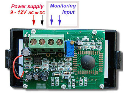
Looks like it takes 9-12V AC or DC.  I don't see why you couldn't feed all of them direct, I'd probably pick a 12V Regulated wall wart for the power.  In any case, what you've picked isn't compatible with a 5V DC output.  I don't see the need for extra power modules, maybe Stan can chime in to let us know what he was thinking, I certainly could be overlooking something.


I do know that most of these meters need a totally isolated power supply from the measured voltage, so you'll want a transformer isolated supply just powering the meters that has no common connection to the track power.


meter

Attachments

Images (1)
  • meter
Originally Posted by gunrunnerjohn:

Looks like it takes 9-12V AC or DC.  I don't see why you couldn't feed all of them direct, I'd probably pick a 12V Regulated wall wart for the power.  In any case, what you've picked isn't compatible with a 5V DC output.  I don't see the need for extra power modules, maybe Stan can chime in to let us know what he was thinking, I certainly could be overlooking something.


I do know that most of these meters need a totally isolated power supply from the measured voltage, so you'll want a transformer isolated supply just powering the meters that has no common connection to the track power.


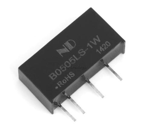
The DC-DC modules in the diagram and described in the OGR thread link are indeed isolated converters...not to be confused with non-isolated $1 LM2596 stepdown buck converters.

Thanks Stan, I figured you had to have a reason for adding the extra parts. I looked for isolation in your description, but I didn't see it, which is why the question.  Of course, a couple posts down, you did clarify they were isolated, but I didn't read the whole thread.


One wonders if it's a problem to use isolated power in parallel for powering the modules.  I suspect the measurement circuit and the power are not isolated, but if you have the same track common for all meters, you might get away without isolated power for those power sources.  That would drop the price and complexity of the meter installation significantly.


If you need isolation, I think I'd just use a bunch of cheap wall-warts, I have tons of them, so that's not an issue for me.

Originally Posted by nvocc5:
So if I used a wall wart (totally isolated power supply) that was 9-12V AC or DC using a bus bar to power the meters it should work with out the DC-DC modules, right?

I would use individual isolated supplies for each digital meter as shown in the diagram.  Or a separate wall-wart for each meter if that's practical to wire up.  The isolated converter supplies are only a few dollars each. 


Originally Posted by gunrunnerjohn:

One wonders if it's a problem to use isolated power in parallel for powering the modules.  I suspect the measurement circuit and the power are not isolated, but if you have the same track common for all meters, you might get away without isolated power for those power sources.  That would drop the price and complexity of the meter installation significantly.

I agree that given a specific situation, it may be possible to power multiple digital meters with a single isolated supply (or wall wart).  But I found the scant technical info on the digital meter listing wrt isolation, impedance, loading, etc.  Plus the isolated DC-DC modules are inexpensive relative to the cost of the digital meter module. 


But as Kris has multiple transformers and is eyeing expansion, I'd want a more general purpose instrumentation panel that is not hand-cuffed to a track wiring configuration.  That is just my opinion.

Dear Gentlemen


Thank you for your answer but I have more questions. This are the information that I got from the vendor:


Operating voltage:AC / DC 8 ~ 12V
Measuring rate:≥2 times / SMeasuring rang:AC 0~ 20A
Over-range display:the first shows "1" or "-1"Operating current:<15mA


Based on the above info this is what I found:


http://www.ebay.com/itm/370412...e=STRK%3AMEBIDX%3AIT


My main consideration is the MA what I need for this project. Example  do I need 4 or 8  these unit for a Postwar ZW, one each for the voltage and one for each Amp meter? Or can I bus bar one unit for all of the voltage and AMP units? Or am I dreaming and each voltage and AMP unit need it's own isolation unit?

Remember that those converters are fairly touchy about the input voltage, so I'd be thinking of a regulated 12VDC power supply as input to the isolation modules.  You can use one power source for all the isolation modules as they are providing total electrical isolation.  I'd probably use this identical converter as it's a lot cheaper and also with free shipping: 371304256443  $3.32.


As Stan says, the safe option is to use individual isolation modules for each meter.  I suspect, though I'd have to personally check, that for a single transformer where the common post is really common to all outputs, that you could get away with fewer converters.  However, without looking at the meters in detail to see how the power source and measurement pins are intertwined, the safe bet is to use individual converters for each meter.  Eight of the ones I mention cost around $26 or so.


Using some numbers from your earlier post, each meter uses 12V and ~15mA.  Power = Volts x Current, so that's 180 mW.  Each isolation converter is rated 1 Watt so no problem using 1 converter per meter.  I think the latest configuration mentioned is 8 converter and meters.  IIRC a regulated 12V DC, 1 Amp wall-wart goes for about $2 on eBay (free shipping). That's 12 Watts so no problem driving 8 converter-meter pairs.

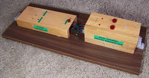
Combination dual channel Circuit Breaker and Analog Voltmeter control box.

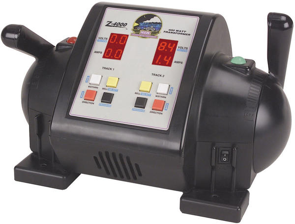
This box is used with an MTH Z-4000 which also has built in digital meters and can be used to monitor either voltage or current. The red lamps on the circuit breaker box shown are used indicate power applied to the track and are illuminated only if the circuit breaker has been reset (in normal condition). 

I operate conventional, MTH DCS and Lionel TMCC engines using this same system. 

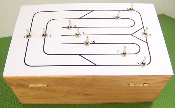
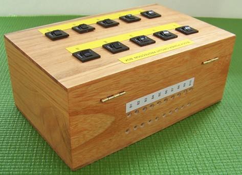
All track blocks are also individually protected with separate circuit breakers and TVS diodes.  Power to each block is controlled by a separate relay.  Each block relay can be controlled by either a DCS AIU or by a separate miniature toggle switch panel.  

An additional dual channel Emergency Stop circuit is used to remove power to all track blocks in an emergency. The E-Stop circuit uses both fixed E-Stop pushbuttons as well as Wireless "fobs".

Since I use DCS in Passive Mode all wiring from the TIU outputs to the track are also protected using TVS diodes. (No power is applied to the TIU inputs when using Passive mode.)

 Dual Channel Monitoring and Protection Panel

MTH 40-4000

BLOCK CONTROL PANEL

BLOCK CIRCUIT BREAKER BOX

Attachments

Images (4)
  • Dual Channel Monitoring and Protection Panel
  • MTH 40-4000
  • BLOCK CONTROL PANEL
  • BLOCK CIRCUIT BREAKER BOX
Last edited by pro hobby

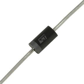
Here is a specification sheet for a typical TVS:

P6KE39CA

Transil™, transient voltage surge suppressor (TVS)

Bidirectional

Description

Transil diodes provide high overvoltage protection by clamping action. Their instantaneous response to transient overvoltages makes them particularly suited to protect voltage sensitive devices such as MOS Technology and low voltage supplied IC’s.

P6KE39CA TVS DIODE

Attachments

Last edited by pro hobby

Add Reply

Post

OGR Publishing, Inc., 1310 Eastside Centre Ct, Suite 6, Mountain Home, AR 72653
800-980-OGRR (6477)
www.ogaugerr.com

×
×
×
×
Link copied to your clipboard.
×
×