Okay...

So a few of the very intense (stan2004, gunrunnerjohn, GGG, Barry of course) DCS intense folks might remember the struggles my club was having with weak DCS signals. Specifically that after a few weeks the excursion voltage of the digital/CDMA signal on the track would fall from like 15V new out of the box, to like 0.1V. We had long discussions here on the forum did lots of measurements, swapped lots of parts but never really nailed it down.

 Well although I've been pretty quiet, we've actually got the whole story worked out now from problem to solution. Before the details... I have to say Jason W and engineering at MTH helped me quite a bit on figuring this thing out.

======== QUICK RECAP ========

Right so let me do a quick recap so everyone knows how this went down. At our club I go around with an oscilloscope every week and measure the DCS voltage levels on each of the 4 outputs on each of our 5 TIUs.  (Only the cool kids bring an oscillscope to a train club?) This is not track power, this is the digital DCS signal. If you need to brush up on DCS signals you can look at the (old post) and (old post2).

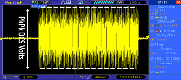
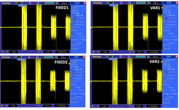
The measurement I do is to send some DCS packets out of each TIU output without it connected to the layout, and measure the DCS pk-to-pk excursion voltage like this:

DCS_measure

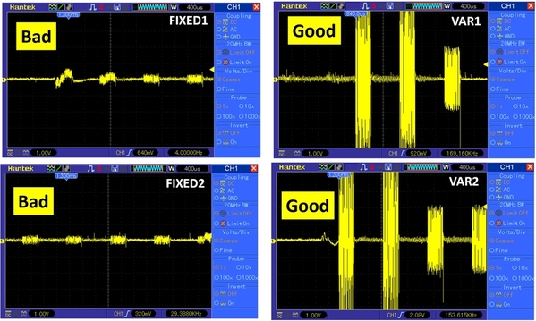
So typically out of the box new the DCS signal pk-pk excursion is about 15V. As we ran our layout we found some sections started to have poor control, then eventually no control. Investigating the DCS signals showed that the channels driving these sections suffered very low output DCS voltage (even when the TIU channel wasn't even connected to the layout). For example here is a TIU pulled out of the layout and measured on the bench with 2 bad channels:

BAD

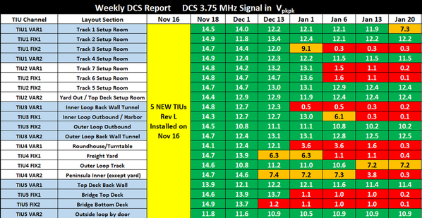
So at first we didn't really understand this too well. We weren't sure how long our layout was like this, and if the TIUs were defective from day 1 or not. On Nov 16 2017 we replaced all 5 TIUs in our club with brand new out of the Box "Rev L" TIUs. From that day on, each week I would measure each TIU channel 1 by 1 (Disconnected from the layout) and write down the excursion number.

Here is our actual log sheet:

DCS_status_1

As you can see from the measurements taken, we only lasted about 2-3 weeks before the DCS levels started dropping on the brand new modules. When we setup the 5 new TIUs on Nov 16 we also installed those PSX-AC units recommended to us by gunrunnerjohn and put the entire layout in passive mode. So that was 5 TIUs and 20 PSX-ACs (A substantial investment!).

After this disaster we decided we would reverse engineer the TIU to try and figure out the root cause of failure. There was a lot of swapping of SMD parts between good and bad channels but nothing really came of it until I talked to Jason W at MTH...


  ======== ROOT FAILURE ========

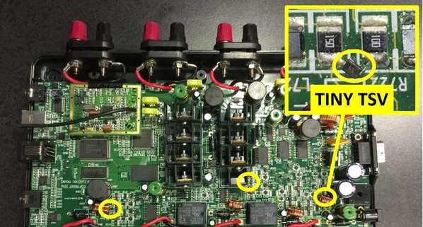
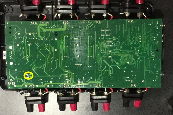
 So the reason we didn't catch the failure with all the swapping is becasue the failing part is well hidden and not actually on the PCB. Somewhere between the TIU rev where they laid out the PCB and the rev L that's sold today someone at MTH engineering decided to add teeny tiny SMD TSVs to protect the ACT244s, but there's no pads for them on the PCB, they are cleverly added to existing components.

Actually all of these tiny TSVs are hidden from plain sight. Var 1 is hidden under the output transformer, Fixed 1 is hidden under a heat-sink, Fixed 2 is on the back, and Var 2 is conspicuously soldered in parallel with another resistor.

TSV_locations

TSV_locations2

So the moment you un-solder these TSVs the signal excursion goes back to normal (although now your ACT244s aren't protected and if something happens you'll be replacing those instead).


All good again:

FreshTIU

I pulled the part number off these TSVs and replaced them, and yeah things worked for a few days (Jan 21,22,23), but then it failed again back to 0.1V (sad). So clearly it was just not a big enough TSV to handle either the peak currents or peak voltages that happen during train mishaps. Actually for some reason, running a lot of Lion Chief trains seems to really fail these diodes faster than MTH or other Lionel trains (maybe something about the motor inductance and peak inverse voltage.... who knows?).


  ======== THE FIX PART 1 ========

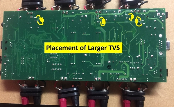
So the first thing we did is try to replace those sad SMD tiny TSVs with bigger ones. The MTH guys showed me other points on the PCB where we could "get at" the same nodes as the original TSV devices. Here is map of that. Sorry I didn't take a photo with the TSVS on when I had it open, and I don't want to open up a working one just to take a photo.... You guys are smart. I'm sure you get the point.

new_TSV_locations

So the TSVs we ended up using are these ones (TSV device). So the idea was just solder them on there in those spots and you should be good to go. Note that TSVs come in 1 of two varieties (one diode and two diode). If you get the one diode one you only have unipolar protection so you need to solder two back to back to get bipolar suppression (yes it matters a lot actually).

We ran the layout like this for a little bit (Jan 24-29) and it mostly worked but we still had the odd failure (like 1-2 channels total). By destroying a few TSVs on the bench I found they don't like to sit in the clamped condition for too long or their clamp voltage starts to drop. With the PSX-ACs in there, that shouldn't happen, but I guess it did.


  ======== OUR CURRENT SOLUTION rev "M?" ========

So the thing about TSVs is they are zener based devices... so they are very fast but they don't like to continuously dissipate power. On the other hand basic rectifier diodes are not very fast switching devices, but they are happy to dissipate power (think rectifier bridge in a power supply) as long as you need. So the obvious design answer was to have two parallel clamps, a fast acting one, and a slower, but beefy one. It just so happens the 9.2V clamp voltage on the TSV is close to an integer multiple of the typical 1n4148 diodes used to support  EE100 lab classes across the country.

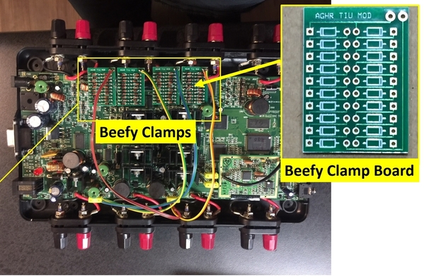
So what we did is build a little daughter board for each channel with two strings of parallel series diodes (up and down) that clamp at roughly 9.1V (about 0.7V X 13). We ran wire to the backside of the board and glued the daughter boards on top of the relays (they do fit, but barely). Since this is the "slow" clamp the wire inductance won't hurt you on the time constant. As I mentioned, we use a basic 1n4148 diode.


It looks like this when everything is in:

beef

  ======== RESULTS ========

I'm not 100% sure why the larger TVS devices are over-stressed but the parallel clamp seems to be working fine so far. While my friends bring trains to run, I bring my oscilloscope and probes to our club and just disconnect and measure each channel one-by-one week after week.


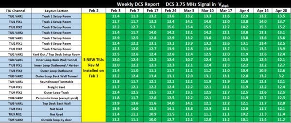
Since updating to this revision "M?" configuration on Feb 2 here are the measurements completed:

DCS_status_2

I've said it's solved 3 times now and been proven wrong, so at this point I'll just say, we've measured the DCS voltages weekly for almost 3 months, and seen no issues, so the evidence is leaning that way. I will continue to measure into the future, and will post if we do see a failure. So far so good though!


   ======== FINAL THOUGHTS ========

The SMD TSVs are so weak, and they fail to like 1-2 ohms across the ACT244 output. Even just a momentary short and you can loose 99% of your signal swing pretty much instantly. Since we put these new revisions in, you really don't get engine "not-on-track" or failure to add engines anymore. Track signals seem solid no matter how horrendous the actual wiring is. I'm sure this failure is a cause of grief for a lot of people besides just us. Of course if you don't have an oscillscope it's hard to tell.

Anyways, the smart MTH guys have all the details, the measurements, and even the PCB layout of my little daughter board, so I guess it's up to them how to proceed with it.


So yeah, if the TIU-train communications are lousy, check the hidden tiny TSVs.

Attachments

Images (9)
  • DCS_measure
  • BAD
  • DCS_status_1
  • TSV_locations
  • TSV_locations2
  • FreshTIU
  • new_TSV_locations
  • beef
  • DCS_status_2
Last edited by Adrian!
Original Post

Replies sorted oldest to newest

WOW  Looks like I'm going to be waiting on additional and upgrades to my TIU.  New requirement to be a model railroader, have a PhD in EE!!

My layout currently in the early stages gives the "Engine not on track" message sometime, even though they will run and I get the double toot all the time.  This with 4 120ft mains with 5 blocks each loop, 2 loops per fixed channel.  Granted I have an old rev H TIU that was given to me, but I am getting by.

Great investigation and hopefully MTH will bring Rev M out before I need to by another.  MTH, please put an outside antenna jack on as well.

As an aside, anyone starting with DCS needs to by Barry's book(s), they are invaluable and saved me some hair.  This forum is great also.

Gray Lackey


Those pesky TVS everyone likes to add to layout and devices, and low an below these short and you don't know it.  These where a fix for Rev L TIU to protect the transmitter.  Good to know.  So what I would love to know, is how long an Sans TVS Rev L or a Rev I last on your layout.  Another component to check when repairing TIUs. Thanks for posting. G

GGG posted:

Those pesky TVS everyone likes to add to layout and devices, and low an below these short and you don't know it.  These where a fix for Rev L TIU to protect the transmitter.  Good to know.  So what I would love to know, is how long an Sans TVS Rev L or a Rev I last on your layout.  Another component to check when repairing TIUs. Thanks for posting. G

Yeah they fail to short-condition because its a zener. If you were super careful you could just run without them, but the component taking the hits will be the ACT244 octal. It's beefier and has an ESD clamp on the chip die, but it's a much more painful thing to change since you need the hot air.

Last edited by Adrian!
David Minarik posted:

One other question:

When the TSV blows, is anything else down the line taken out because of this?

Thanks,

David Minarik posted:

Adrian,

Would this problem be the same in all or most REV TIUs or just REV Ls?

Thank you for posting this!


I haven't been in the hobby that long so I don't know when these TSVs made their debut. It looks recent. Others here probably know better than me.

Well, you don't really need hot air to change the ACT244, but I'll allow it's a lot harder to replace than the little TVS.  I simply cut all the legs off the old one right at the body, then sweep the remains of the legs off the pads with the iron, then position and solder the new chip on.

That's excellent work on the fix, and I'd have never imagined you could take out the 500W TVS so quickly across those parts.

Would you post a schematic of the diode PCB, I'd like to take a closer look at perhaps a more compact solution.  I use SMT diodes that would have similar characteristics as the 1N4148, it would be easy to do a more compact board.  Now that a solution is at hand, maybe there's a more compact clamping solution to be had, perhaps even other than multiple diodes.

One question arises, the diodes would only clamp in one direction, are you using two sets of them to clamp the bi-polar signal?

Last edited by gunrunnerjohn
gunrunnerjohn posted:

Well, you don't really need hot air to change the ACT244, but I'll allow it's a lot harder to replace than the little TVS.  I simply cut all the legs off the old one right at the body, then sweep the remains of the legs off the pads with the iron, then position and solder the new chip on.

That's excellent work on the fix, and I'd have never imagined you could take out the 1500W TVS so quickly across those parts.

Would you post a schematic of the diode PCB, I'd like to take a closer look at perhaps a more compact solution.  I use SMT diodes that would have similar characteristics as the 1N4148, it would be easy to do a more compact board.  Now that a solution is at hand, maybe there's a more compact clamping solution to be had, perhaps even other than multiple diodes.

One question arises, the diodes would only clamp in one direction, are you using two sets of them to clamp the bi-polar signal?

Hey,

I never did a schematic because it was too simple, I just drew it out-right. Compact 1n4148s would work but if time was spent you could find a rectifier with a higher drop so you wouldn't need so many.

Here's a doodle:

fig4

I tried both the bidirectional and unidirectional (two back to back, just like you're thinking) TVS diodes, but they're both pretty much the same IV characteristic. In the end the reason I went with the unipolar one for the complicated reason that they were in stock on digikey, while the bipolar ones were not.

The 1n4148s are two parallel strings up and down.


Attachments

Images (1)
  • fig4
Last edited by Adrian!

Oh yeah, other details:

1. In the original post I said 13 clamping diodes but it's really 10. It was 13 on the breadboard but 10 on the final PCB. I wanted the big clamp voltage a little lower than the small clamp voltage to try and get an early turn on.

2. If the original tiny TVS fails and sits that way for more than a few minutes (like a day) then the ACT244 is usually damaged too (since it's been sending commands to a short circuit instead of a train). So if you lift off the diodes and the swing doesn't come back, that's the next thing to look at.

OK, so a single diode board is used for one output, and you just have two diode strings back to back.  That's what I was wondering about.  I was thinking along the lines of a higher drop, or even some active circuit that didn't require so many components.  Also, it would probably all be put on one board with wiring to the appropriate places for all four channels.

I always start with a schematic as I'm too lazy to manually route, I just let the auto-router do that job.

Maybe three of these in each direction would do the clamping in a much more compact form?  Sanken EG01CV1, six instead of 22 diodes would be a lot easier to deal with.   I'm also not sure you need the TVS as well, I'd think these would do the trick.


Last edited by gunrunnerjohn
gunrunnerjohn posted:

OK, so a single diode board is used for one output, and you just have two diode strings back to back.  That's what I was wondering about.  I was thinking along the lines of a higher drop, or even some active circuit that didn't require so many components.  Also, it would probably all be put on one board with wiring to the appropriate places for all four channels.

I always start with a schematic as I'm too lazy to manually route, I just let the auto-router do that job.

Maybe three of these in each direction would do the clamping in a much more compact form?  Sanken EG01CV1, six instead of 22 diodes would be a lot easier to deal with.


Exactly!

Yeah those might work. The best thing to do is buy a handful and put them under full conduction for an hour and see if the knee voltage changes over time.


gunrunnerjohn posted:

You could also up the rating of the TVS slightly to insure the diodes are taking the heat if the response is too slow

Hey,


It’s tricky to drop the TVS devices...., rectifier diodes are a very soft IV so they are a gentle clamp, while TVS chop voltage like a straight line. You’d have to test to make sure you were turning on fast enough but not so early in excursion that you start chopping the dcs signal itself .... I bet you can get it with some fine tuning though.

also theres other speed considerations.... it’s a bit complicated but basically the TIU pcb has a ground and vdd plane so the traces on it look like microstrip lines (real part only... no jX) with low impedance terminations since the transformer and ACT244 outputs are low impedance.

Once you have a long umbical cable you start picking up inductance that can hurt your time constant. That’s the advantage of soldering the TVS right on the spot.

I only had to make 5 sets and it was a prototyping exercise so nothing was a final print .... but If I had to do 500 I’d probably do a very very low profile small area board like 0.5” x 0.5” with SMD diodes and have two vias on the back that solder directly to the points on the main pcb. That keeps the time constant up and reduces the labor per.

Again, you’re good at PCBs so I’m sure you could tighten it up a lot.


This is seems to be a Great Upgrade, MTH should incorporate this and an external antenna port, into a new Rev"M" TIU ASAP, and also develop an upgrade component for Techs, Thanks for all your work and persistance on this. I met Jason a few years ago, May have been in San Diego or Pasadena,  a good guy in the business. 

Thanks Again, RWDeano

A good idea to attach the PCB directly to the ACT244, it would probably not be too difficult to rig something that solders to the top side right on the chip to keep the leads short.  Then you could put the TVS and diodes on one board.  I'd have to do more research to see how this plays out.

I wonder if MTH is actually going to do something with this to prevent this issue.  I know the NJ-HR folks have had similar issues with their TIU's, this explains what is happening I suspect.

I've read this whole post and passing it on to our Electrical Engineer cub member. I know he will understand what you folks are talking about. We have too many witches brews on our layout trying to maintain a dependable "DCS" signal strength. This sounds like this guy figured out the fix.........Very much thank you for your perseverance, in coming to a resolve...

AlanRail posted:

Great for EEs. What do the rest of us do in the meantime??!

I see a small cottage industry for someone to fix TIUs Rev Ls ; I can't imagine MTH taking this on as a warranty repair.

Everything here is open to use as far as I’m concerned, I just want to help people avoid the problems I’ve been having. Maybe one of the professionals like GGG or gunrunnerjohn can do the mods for folks

its not expensive, maybe $10 a TIU in quantity. The pcb is more, but I only made 25 so a larger volume would benefit there too.

(or just “run” the trains without power)


Last edited by Adrian!
Ron_S posted:

A question from the peanut gallery, can the TVS be put between the power supply and the TIU?

Engineer-Joe posted:

anything we could put in front of the TIU to handle the spikes so this wouldn't occur?

It's not so simple actually. You want the TVS right up against whatever it's protecting:

There's a little bit of RF design principles here (sorry it's complicated)... let me try to explain it easily:

What happens when a train derails is the motor and bouncing contacts produce transient events (fast changing voltages and currents over a short time duration... like 1-10ns range). These transient events are short in time which means they are very wide-band in frequency (fourier transform describes this).

They can be up to the GHz range,  which means they behave like RF waves on the wiring and track (because they have a comparable wavelength in the 10s of inches regime). Once you are into this wave propagation behavior it means that the whole wire length is not the same voltage at the same time. So just because you null out the voltage at one point along the wire with the TVS between the train and the TIU doesn't mean the transient voltage at the TIU or train is zero because of the waves bouncing up and down the wire.

If you want the basics it's here: Transmission lines

So the only way to be 100% sure the transient voltage at the protected device is safely held down by the TVS is to physically place it very close to the thing your protecting (like within 1/10th of a wavelength). That's why it has to go right on the board inside the TIU.

Hope that wasn't too poorly explained!

Adrian! posted:
Ron_S posted:

A question from the peanut gallery, can the TVS be put between the power supply and the TIU?

Engineer-Joe posted:

anything we could put in front of the TIU to handle the spikes so this wouldn't occur?

It's not so simple actually. You want the TVS right up against whatever it's protecting:

There's a little bit of RF design principles here (sorry it's complicated)... let me try to explain it easily:

What happens when a train derails is the motor and bouncing contacts produce transient events (fast changing voltages and currents over a short time duration... like 1-10ns range). These transient events are short in time which means they are very wide-band in frequency (fourier transform describes this).

They can be up to the GHz range,  which means they behave like RF waves on the wiring and track (because they have a comparable wavelength in the 10s of inches regime). Once you are into this wave propagation behavior it means that the whole wire length is not the same voltage at the same time. So just because you null out the voltage at one point along the wire with the TVS between the train and the TIU doesn't mean the transient voltage at the TIU or train is zero because of the waves bouncing up and down the wire.

If you want the basics it's here: Transmission lines

So the only way to be 100% sure the transient voltage at the protected device is safely held down by the TVS is to physically place it very close to the thing your protecting (like within 1/10th of a wavelength). That's why it has to go right on the board inside the TIU.

Hope that wasn't too poorly explained!

Previous advice seen here: TVS placed across the TIU output(s) does the trick, yes/no?

Kerrigan posted:
Adrian! posted:
Ron_S posted:

A question from the peanut gallery, can the TVS be put between the power supply and the TIU?

Engineer-Joe posted:

anything we could put in front of the TIU to handle the spikes so this wouldn't occur?

It's not so simple actually. You want the TVS right up against whatever it's protecting:

There's a little bit of RF design principles here (sorry it's complicated)... let me try to explain it easily:

What happens when a train derails is the motor and bouncing contacts produce transient events (fast changing voltages and currents over a short time duration... like 1-10ns range). These transient events are short in time which means they are very wide-band in frequency (fourier transform describes this).

They can be up to the GHz range,  which means they behave like RF waves on the wiring and track (because they have a comparable wavelength in the 10s of inches regime). Once you are into this wave propagation behavior it means that the whole wire length is not the same voltage at the same time. So just because you null out the voltage at one point along the wire with the TVS between the train and the TIU doesn't mean the transient voltage at the TIU or train is zero because of the waves bouncing up and down the wire.

If you want the basics it's here: Transmission lines

So the only way to be 100% sure the transient voltage at the protected device is safely held down by the TVS is to physically place it very close to the thing your protecting (like within 1/10th of a wavelength). That's why it has to go right on the board inside the TIU.

Hope that wasn't too poorly explained!

Previous advice seen here: TVS placed across the TIU output(s) does the trick, yes/no?

Maybe..... The plastic terminals are still a few inches away from the octal driver chips that are being protected. Also the PCB isn’t made of air so the wavelength is even shorter.

you can try it and see. The catch is you’ll need an oscilloscope and weeks of measurements to validate if it’s actually fixed or not.

That’s the part I can’t emphasize enough actually.... this has been more like a clinical trial than a design check. You never know what’s going to happen in the club so you have to measure over a long period to validate everything is okay. Adjusting the TIU is trivial ...but lugging the scope under the table with an extension cord and disconnecting the layout channels one by one for 5 TIUs and measuring signals is like a 1 hour start to every club visit.

Add Reply

Post
The DCS Forum is sponsored by

OGR Publishing, Inc., 1310 Eastside Centre Ct, Suite 6, Mountain Home, AR 72653
800-980-OGRR (6477)
www.ogaugerr.com

×
×
×
×
Link copied to your clipboard.
×
×