gunrunnerjohn posted:Bob, no images found.

John
I just resent it.


|
|
gunrunnerjohn posted:Bob, no images found.
John
I just resent it.
John,
I think I cracked that mystery. I set the remote into SPEED mode so I wouldn't keep complaining about not finding the engine, that probably affects how the test responds. When I go back to NORMAL mode, the test just hangs as I'd expect if it doesn't find an engine.
That makes perfect sense. Speed Mode causes the remote to assume a correct response to all commands that the remote sends.
However, since Speed Mode is supposed to return to 2-way command mode for commands that require it, such as adding or recovering an MTH engine, it seems that a DCS signal test should cause it to do so, as well, but does not.
gunrunnerjohn posted:Well, it's official. The ACT244's certainly seem to degrade in normal use. I don't think I put unusual stress on this TIU, but here's the Variable #1 channel before and after the replacement of the ACT244 chip at U340. So, it doesn't take the errant TVS to kill them, they can die all on their own.
GRJ
GREAT! What is the Digikey number for the chip.
rad400 posted:gunrunnerjohn posted:Well, it's official. The ACT244's certainly seem to degrade in normal use. I don't think I put unusual stress on this TIU, but here's the Variable #1 channel before and after the replacement of the ACT244 chip at U340. So, it doesn't take the errant TVS to kill them, they can die all on their own.
GRJ
GREAT! What is the Digikey number for the chip.
Here is a search for appropriate parts with small quantity ordering.
Naturally, I pick the cheapest one if I can. ![]()
Barry Broskowitz posted:However, since Speed Mode is supposed to return to 2-way command mode for commands that require it, such as adding or recovering an MTH engine, it seems that a DCS signal test should cause it to do so, as well, but does not.
Yep, probably just an oddity in the way they handled it in the software. I rarely run in SPEED mode, so I doubt I've ever tried a track signal test in that mode. The only reason to do it here is so I could do my testing of the signals.
"So, it doesn't take the errant TVS to kill them, they can die all on their own."
GRJ, are you saying that the service bulletin mod is going to make no difference--the ACT244 is doomed no matter what?
No, I'm saying that the previous fix with the small TVS that shorted and caused the ACT244 to fail is not the only way they can be killed. Mine had no mods, and no added TVS in the signal circuit, and three of the four ACT244 chips have partially failed. Truthfully, I don't know how effective the service bulletin mod is going to be. Adrian previously used a 500W TVS and they were dying in his environment as well. Time will tell if it's effective.
GRJ, hate to keep bothering you since you have a business to run, with reference to the diagram on the 3rd page of the Service Bulletin, what number are the ACT244 chips?
I assume that the ACT244 was one of the improvements in the Rev L over earlier versions????
Hi Guys.....
I've been reading all these posts with great interest to see what will fall out of this.
I am not an electrical engineer. I do not claim to understand all the discussions. I am a hobbiest who likes to run his trains and enjoy all that DCS has to offer. And I do SINCERELY appreciate all the help and guidance you all on this forum provided to me and many others from time to time. I'd be pretty lost without you.
My question is.....what does a person like me do? I run my layout with 2 TIUs. I went out and bought 2 new Rev L's because reviews indicated that was the way to go.....that was my choice and I accept that.
But what do I do now? Are my Rev L TIUs affected by these hardware issues? I don't know. Have I had derailments? You bet. Do I just bite the bullet and send the TIUs in for repair?
To say that this situation is frustrating for me is an understatement.
I just want to know what model railroader hobbiests like myself who have made a substantial investment in MTH and DCS need to do next.
It appears though that this discussion is far from over and I need to "sit tight" as those far more knowledgeable than I find other issues with the Rev. L design before taking any action (sorry for the run-on sentence).
Very frustrating indeed......
Junior, at least two of us, John and myself, have rev Ls that never came with the tiny TVS's. Both of ours continue to work. I have put a scope on mine and it shows full output of 6-8v P-P on all channels. If yours stops working then send it to an MTH tech and have it repaired. For any electronics guy worth his/her salt this is a simple repair.
John, I would suggest doing at least one TIU, yours or your clubs with one channel using MTH's suggested component for a comparison. If theirs fails and yours doesn't then maybe MTH will adopt your fix.
Pete
Norton posted:Junior, at least two of us, John and myself, have rev Ls that never came with the tiny TVS's. Both of ours continue to work. I have put a scope on mine and it shows full output of 6-8v P-P on all channels. If yours stops working then send it to an MTH tech and have it repaired. For any electronics guy worth his/her salt this is a simple repair.
John, I would suggest doing at least one TIU, yours or your clubs with one channel using MTH's suggested component for a comparison. If theirs fails and yours doesn't then maybe MTH will adopt your fix.
Pete
8V pk-pk is about where the trouble starts. 14V is perfect 12V is okay, 10V is where things get noticeably slow with adding engines
Junior posted:Hi Guys.....
I've been reading all these posts with great interest to see what will fall out of this.
I am not an electrical engineer. I do not claim to understand all the discussions. I am a hobbiest who likes to run his trains and enjoy all that DCS has to offer. And I do SINCERELY appreciate all the help and guidance you all on this forum provided to me and many others from time to time. I'd be pretty lost without you.
My question is.....what does a person like me do? I run my layout with 2 TIUs. I went out and bought 2 new Rev L's because reviews indicated that was the way to go.....that was my choice and I accept that.
But what do I do now? Are my Rev L TIUs affected by these hardware issues? I don't know. Have I had derailments? You bet. Do I just bite the bullet and send the TIUs in for repair?
To say that this situation is frustrating for me is an understatement.
I just want to know what model railroader hobbiests like myself who have made a substantial investment in MTH and DCS need to do next.
It appears though that this discussion is far from over and I need to "sit tight" as those far more knowledgeable than I find other issues with the Rev. L design before taking any action (sorry for the run-on sentence).
Very frustrating indeed......
So you're an example of the person I'm thinking about most actually....
Helping you requires 2 things to happen:
1. A way for you to diagnose your TIU without needing a BSEE degree and a $500 scope.
I'm trying to work out a simple test tool (trying to keep it under $50) that can be used to quickly check each TIU output and just give you a thumbs up or down without a lot of software or circuit measurement knowledge. Stan2004 is thinking about this too it seems. The DCS signals are fast, infrequent and complicated so it's not as easy as just measuring track voltage, but we really are working on some ideas.
2. A repair that won't break again:
The mod I've done in our club and the SD3R club (TVS + silicon clamps) seems to be invincible, we haven't seen any damage in 7 months. The signals remain 14V pkpk week after week since Nov 2017. The MTH mod in the service bulletin is half of the mod we did (the TVS without the silicon clamps). In that condition we did see failures, not not as frequent as the bare Rev L TIU. The TVS devices are easy to put in, but the clamps are complicated and require a lot of rework and parts meaning it's not too practical for MTH to offer it. My setup is very prototype-ish and needs serious work to install but guys like GRJ are working out cleaner and easier to apply versions. Perhaps the answer will be to send your TIUs to someone like him if you want the highest level of robustness.
Norton posted:Junior, at least two of us, John and myself, have rev Ls that never came with the tiny TVS's. Both of ours continue to work. I have put a scope on mine and it shows full output of 6-8v P-P on all channels. If yours stops working then send it to an MTH tech and have it repaired. For any electronics guy worth his/her salt this is a simple repair.
John, I would suggest doing at least one TIU, yours or your clubs with one channel using MTH's suggested component for a comparison. If theirs fails and yours doesn't then maybe MTH will adopt your fix.
Pete
Pete, I see that Adrian beat me to it, 8V P-P is too low, that indicates that probably two of the four gates in the 244 have already failed. You should be getting around 14-15V P-P with a properly functioning TIU, see my previous post before and after replacing the 244 for the failing channel.
Thanks Pete and Adrian for responding to my fear and frustration. I realize this discussion is well into 7 pages...but after reading your 2 posts, I thought it might be helpful to document in one place what the "symptoms" are for Rev L TIU failures (especially for those of us who aren't electrical engineers....sorry....running on again).
Is difficulty adding a MTH engine the only symptom? Or is there a combination of things? That would be helpful to know.
Adrian....I like your idea of a diagnostic tool for the TIU that hobbiest like me would be able to use. It would be cool if it could be modeled after OBDII readers used to diagnose car issues.
Thanks again for the responses.....its good to know people on this forum (like you guys) have the backs of hobbiest like me.
Adrian, my little board will still require soldering to the chips, but it can all be done on top, and it's a lot less components. It's yet to be proven that it will actually solve the problem, so I don't want to turn it loose until that is fully tested.
It does look pretty cute perched on the ACT244 chip. ![]()
gunrunnerjohn posted:Adrian, my little board will still require soldering to the chips, but it can all be done on top, and it's a lot less components. It's yet to be proven that it will actually solve the problem, so I don't want to turn it loose until that is fully tested.
It does look pretty cute perched on the ACT244 chip.
Thank you. Thank you. Thank you.
I hate taking the board out of the TIU. Tightening and loosening those squeezy terminals is the worst.
Junior posted:Thanks Pete and Adrian for responding to my fear and frustration. I realize this discussion is well into 7 pages...but after reading your 2 posts, I thought it might be helpful to document in one place what the "symptoms" are for Rev L TIU failures (especially for those of us who aren't electrical engineers....sorry....running on again).
Is difficulty adding a MTH engine the only symptom? Or is there a combination of things? That would be helpful to know.
Adrian....I like your idea of a diagnostic tool for the TIU that hobbiest like me would be able to use. It would be cool if it could be modeled after OBDII readers used to diagnose car issues.
Thanks again for the responses.....its good to know people on this forum (like you guys) have the backs of hobbiest like me.
Generally it goes like this:

Yep, I wanted a solution that just required you to work on the top. However, it was good I took the TIU apart, half the terminals were very loose!
gunrunnerjohn posted:Norton posted:Junior, at least two of us, John and myself, have rev Ls that never came with the tiny TVS's. Both of ours continue to work. I have put a scope on mine and it shows full output of 6-8v P-P on all channels. If yours stops working then send it to an MTH tech and have it repaired. For any electronics guy worth his/her salt this is a simple repair.
John, I would suggest doing at least one TIU, yours or your clubs with one channel using MTH's suggested component for a comparison. If theirs fails and yours doesn't then maybe MTH will adopt your fix.
Pete
Pete, I see that Adrian beat me to it, 8V P-P is too low, that indicates that probably two of the four gates in the 244 have already failed. You should be getting around 14-15V P-P with a properly functioning TIU, see my previous post before and after replacing the 244 for the failing channel.
I assume to get 14v you are using a transformer on the fixed one set at 20v RMS and a high pass filter to get rid of the 60hz?
I was using a 12v DC wall wart. I will retest with an AC transformer.
Pete
The PCB boards arrived from OSH park tonight, I will have to set them aside for a week while take care of family business in the northwest, but look forward to making up 2 sets and upgrading 2 TIU's for the club layout, I am also looking forward to seeing if new ACT244 chips refresh some of the burned out TIU's at the club and here at home.
Yesterday I repaired another TIU with a dead 74ACT244 on Fixed 1. When I tested it with the new chip, I was only getting a signal test of 8 to 9 on my test track. All other channels have a good 10. So I installed another 74ACT244 thinking maybe I got the first one too hot. I'm still only get 8 to 9 at best. The chips were removed using the Quik Chip method and soldered in dragging the iron. No stress was ever applied to the board traces. I also went through the steps to make sure all Quik Chip solder was removed from the pads and the iron. The post are all tight and have the star washer and lock nut installed. This repair was done on a REV I3. I hate to open up a new can of worms here, but what other component is there that can cause a weak signal, up stream or maybe even down stream of the 74ACT244? I really wish a manufacture would make a socket for the ACT244"s that could be soldered to the pads on the board.
Dave Zucal posted:Yesterday I repaired another TIU with a dead 74ACT244 on Fixed 1. When I tested it with the new chip, I was only getting a signal test of 8 to 9 on my test track. All other channels have a good 10. So I installed another 74ACT244 thinking maybe I got the first one too hot. I'm still only get 8 to 9 at best. The chips were removed using the Quik Chip method and soldered in dragging the iron. No stress was ever applied to the board traces. I also went through the steps to make sure all Quik Chip solder was removed from the pads and the iron. The post are all tight and have the star washer and lock nut installed. This repair was done on a REV I3. I hate to open up a new can of worms here, but what other component is there that can cause a weak signal, up stream or maybe even down stream of the 74ACT244? I really wish a manufacture would make a socket for the ACT244"s that could be soldered to the pads on the board.
The general flow is like:
FPGA to select mux.
Select mux to ACT244 Drivers.
ACT244 drivers to conditioner network.
Conditioner network to transformer.
So check pin 11 and pin 4 on the ACT244 in question. If those are happy 5V square waves move into the conditioning, if they are not, go back and look at the mux. In the conditioner there's about 5-6 discrete transistors in with the passives that may get you. The last thing is the ferrite transformer that does the superposition. That's all there is in there.
Gentlemen, I would appreciate it if you could answer a couple of simple questions.
On page 3 of the Service Bulletin, what is the ID number(s) for the ACT244s?
Did pre-Rev-L TIUs use the ACT 244?
Since the surges that damage the ACT244s (unless they just "wear out") originate in derailments, would it make sense to install a heavy duty TVS in each block, near the single centerrail drop called for by DCS, to snub the surge before heading to the TIU. I do recognize that TVSs should be near to the device they protect, but seems to me that snubbing the surge can take place anywhere between origin and victim. ????
RJR posted:Gentlemen, I would appreciate it if you could answer a couple of simple questions.
On page 3 of the Service Bulletin, what is the ID number(s) for the ACT244s?
Did pre-Rev-L TIUs use the ACT 244?
Since the surges that damage the ACT244s (unless they just "wear out") originate in derailments, would it make sense to install a heavy duty TVS in each block, near the single centerrail drop called for by DCS, to snub the surge before heading to the TIU. I do recognize that TVSs should be near to the device they protect, but seems to me that snubbing the surge can take place anywhere between origin and victim. ????
The transient events are actually pretty high bandwidths up to 100s of MHz so nulling the voltage at the track doesn’t necessarily mean you’ve nulled it at the TIU because you’re in the “telegrapher’s” regime where the wavelength and wire length are comparable.
The only way to guarantee a null at a particular position along the line is to impose the null at that position:
Vtotal(z)=VP e^Yz + Vn e^-Yz
Thank you, Adrian for addressing my third question. I don't understand the electronics, but do understand the second paragraph.
RJR posted:Thank you, Adrian for addressing my third question. I don't understand the electronics, but do understand the second paragraph.
Helpful analogy:
It’s like a 20ft string tied to the wall at one end and you wave the other end up and down. If the string is long (like the layout wires) and you wave your hand up and down fast enough (high enough bandwidth) there will be parts of the string that look like they aren’t moving in the middle.
Then If you pinch the string at those spots (put the TVS) it doesn’t mean the string won’t still be moving to the left and right of where you’re holding it. The only way to make sure a particular spot on the string isn’t moving is to pinch it at that spot.


Adrian! posted:Junior posted:Thanks Pete and Adrian for responding to my fear and frustration. I realize this discussion is well into 7 pages...but after reading your 2 posts, I thought it might be helpful to document in one place what the "symptoms" are for Rev L TIU failures (especially for those of us who aren't electrical engineers....sorry....running on again).
Is difficulty adding a MTH engine the only symptom? Or is there a combination of things? That would be helpful to know.
Adrian....I like your idea of a diagnostic tool for the TIU that hobbiest like me would be able to use. It would be cool if it could be modeled after OBDII readers used to diagnose car issues.
Thanks again for the responses.....its good to know people on this forum (like you guys) have the backs of hobbiest like me.
Generally it goes like this:
Adrian!
I LOL on your "TIU Channel Status"es! Hysterical but to the point. The DCS Symptoms chart is absolutely PERFECT!
Thanks for doing this.
gunrunnerjohn posted:Pete, I see that Adrian beat me to it, 8V P-P is too low, that indicates that probably two of the four gates in the 244 have already failed. You should be getting around 14-15V P-P with a properly functioning TIU, see my previous post before and after replacing the 244 for the failing channel.
Ok, I rechecked mine using a transformer on Fixed 1. I get 12v P-P on Fixed 1 and 14v P-P on Fixed two which I never use. I expect the two variable channels are fine as week as they never get used. I will order parts to have on hand but hold tight until something breaks.
I have to say it seems odd that these devices fail gradually instead of with a bang.
Pete
I have an early Rev L TIU which I imagine was made before any TVS revisions, but I have never looked to be sure. Like Junior, I have no way to check the outputs nor would I know how to if I did have the equipment. ![]() My DCS system is still working just fine with no noticeable problems that I can see, so I will continue using it, follow this thread and hope for the best before it breaks. This is a very interesting discovery you all are discussing here!
My DCS system is still working just fine with no noticeable problems that I can see, so I will continue using it, follow this thread and hope for the best before it breaks. This is a very interesting discovery you all are discussing here!
Also, I really appreciate the work you all are doing here, even though its still over my head. I still like following along. It's great to have folks here that actually understand this stuff. Thanks again to all of you for your work and all the time you have been putting in on this!!
Norton posted:gunrunnerjohn posted:Pete, I see that Adrian beat me to it, 8V P-P is too low, that indicates that probably two of the four gates in the 244 have already failed. You should be getting around 14-15V P-P with a properly functioning TIU, see my previous post before and after replacing the 244 for the failing channel.
Ok, I rechecked mine using a transformer on Fixed 1. I get 12v P-P on Fixed 1 and 14v P-P on Fixed two which I never use. I expect the two variable channels are fine as week as they never get used. I will order parts to have on hand but hold tight until something breaks.
I have to say it seems odd that these devices fail gradually instead of with a bang.
Pete
Whoa! This is a new twist. So in your initial measurement (8V P-P) the 12V DC wall-wart was into Fixed1?
Anecdotally, DCS operates better on DC than AC. But in this sample of 1, it appears going from DC to AC increases the DCS signal level from 8V P-P (on all channels) to 12V P-P (Fixed1) and 14 P-P (Fixed2). Hmm.
As described in earlier posts, the ACT244 is the originator of the DCS-signal. That's a 5V IC chip. It does not matter what the TIU power source is (AC or DC). AC and DC supplies are or course not created equal, so it could be that your particular AC and DC supplies load down the DCS signal differently than two random other supplies. I don't think we want to go down this rabbit hole (yet). So to keep the conversation focused I think it should be specified that we are talking about an AC transformer power source so that everyone is measuring the same thing.
stan2004 posted:Norton posted:gunrunnerjohn posted:Pete, I see that Adrian beat me to it, 8V P-P is too low, that indicates that probably two of the four gates in the 244 have already failed. You should be getting around 14-15V P-P with a properly functioning TIU, see my previous post before and after replacing the 244 for the failing channel.
Ok, I rechecked mine using a transformer on Fixed 1. I get 12v P-P on Fixed 1 and 14v P-P on Fixed two which I never use. I expect the two variable channels are fine as week as they never get used. I will order parts to have on hand but hold tight until something breaks.
I have to say it seems odd that these devices fail gradually instead of with a bang.
Pete
Whoa! This is a new twist. So in your initial measurement (8V P-P) the 12V DC wall-wart was into Fixed1?
Anecdotally, DCS operates better on DC than AC. But in this sample of 1, it appears going from DC to AC increases the DCS signal level from 8V P-P (on all channels) to 12V P-P (Fixed1) and 14 P-P (Fixed2). Hmm.
As described in earlier posts, the ACT244 is the originator of the DCS-signal. That's a 5V IC chip. It does not matter what the TIU power source is (AC or DC). AC and DC supplies are or course not created equal, so it could be that your particular AC and DC supplies load down the DCS signal differently than two random other supplies. I don't think we want to go down this rabbit hole (yet). So to keep the conversation focused I think it should be specified that we are talking about an AC transformer power source so that everyone is measuring the same thing.
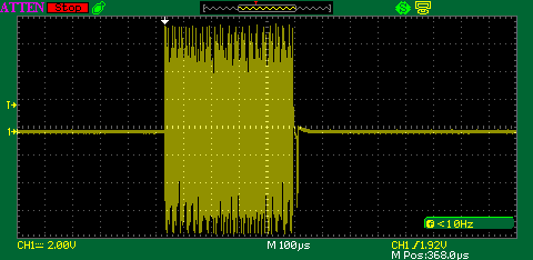
For comparison you probably all want to be measuring the unloaded condition (the Thevenin voltage). So power (lets keep it AC for the disucssion) flowing into the INPUT side, and only the scope/filter on the OUTPUT side. That's the condition I measure under.
Also I make sure not to measure the overshoots, otherwise everything becomes complicated. Instead I measure the flat-tops of the line code signal. The overshoots are a higher voltage but they don't exist across the entire symbol time so there's no guarantee they are there at the sampling instant in the decoder. Also they are a function of the frequency response of the layout, test cable or w/e.
Here's a figure showing what I mean:

Theoretically the best you can do with the ACT244 driver (5V Vdd) operating fully differential is 10V. Then driving the 1:1.414 (sqrt[2]) turn ratio output transformer gets you to 14V. If you are measuring more than 14V you are probably considering the overshoot portion of the waveform.
Adrian, I noticed the overshoot on a few of the samples I've taken have been substantial, you can get 20V readings if you just believe the 'scope peak levels. ![]()
FWIW, I get a bit over 14V maximum with all that I've seen that are running at peak.
Hi Guys.....
Well....looks like my Rev L TIU is either failing or has failed.
I was running 3 trains on Saturday just fine.....no issues.
On Sunday when I turned on the main power switch (the 4 PW ZW transformers and TIU are all plugged into the same switched power strip):
1. Two PS3 engines immediately took off like bandits (the Var channels are set to Fixed and the ZWs are all set at 17 volts). This prompted an immediate power shut down at the power strip,
2. One PS2 steamer was not responding to commands,
3. One TMCC engine seemed to be responding normally.
I had to do a conventional reset on the two PS3 engines using a separate MTH transformer....they were both stuck in forward.
Everything was powered down and the engines were put back on the track (one at a time separately) and powered everything back up.
When Start Up on the PS3 engine was attempted, the "Engine not on Track" message displayed.
An Engine Reset was done followed by engine Start Up....same "Engine not on Track" was displayed. This was attempted for both PS3 engines.
An engine Factory Reset followed by attempts to Add the engine was attempted. No luck....got the message "Engine not Found". This was attempted for both PS3 engines.
Complete resets of the TIU and remote proved fruitless. The same results described above were experienced for all MTH engines.
The Rev L TIU was replaced with a Rev I. Resets of the TIU and remote were done. The same engines above were successfully added and are successfully running.
Sigh..........I think the Rev L is toast.
Junior,
Did you:
Barry Broskowitz posted:Junior,
Did you:
- Try using each of the 4 TIU channels?
- Make sure that the TIU's red LED was on?
- Power cycle the TIU?
- Feature Reset the TIU?
- Tether the TIU to the remote?
Hey Barry....
.I use all 4 channels. My layout is split into track blocks (approx 10 sections each). Variable channels are set to Fixed.
.TIU red light was on.
.Unless you mean something else; when I do a "power down" at the power strip.....that process includes the transformers and the TIU.
.I tried multiple Feature Resets and Factory Resets.
.Darn....forgot to try tethering the Remote.
You peaked my interest...now that I have the Rev L TIU pulled from the layout I can hook it to my test track strip and see what it does standalone. That way I can test each channel separately.
Thanks! 😁
Junior, after doing your resets, did you change your variable channels back to fixed?
Hi Dave....
Oh yeah....sure did set the Variables back to Fixed. That almost tripped me up the 1st of the several times I did complete resets. I caught it quickly the 1st time because the engine (MTH Santa Fe FP45) was pulling a string of lit passenger cars.
Good thought though 😁
Barry, you still have the stickers on your glasses
Matt,
No, I do not.
What you're seeing is a reflection of my computer screen. I took the picture for the avatar using the FaceTime camera on my Mac.
Access to this requires an OGR Forum Supporting Membership