Okay...

So a few of the very intense (stan2004, gunrunnerjohn, GGG, Barry of course) DCS intense folks might remember the struggles my club was having with weak DCS signals. Specifically that after a few weeks the excursion voltage of the digital/CDMA signal on the track would fall from like 15V new out of the box, to like 0.1V. We had long discussions here on the forum did lots of measurements, swapped lots of parts but never really nailed it down.

 Well although I've been pretty quiet, we've actually got the whole story worked out now from problem to solution. Before the details... I have to say Jason W and engineering at MTH helped me quite a bit on figuring this thing out.

======== QUICK RECAP ========

Right so let me do a quick recap so everyone knows how this went down. At our club I go around with an oscilloscope every week and measure the DCS voltage levels on each of the 4 outputs on each of our 5 TIUs.  (Only the cool kids bring an oscillscope to a train club?) This is not track power, this is the digital DCS signal. If you need to brush up on DCS signals you can look at the (old post) and (old post2).

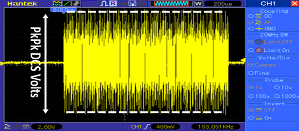
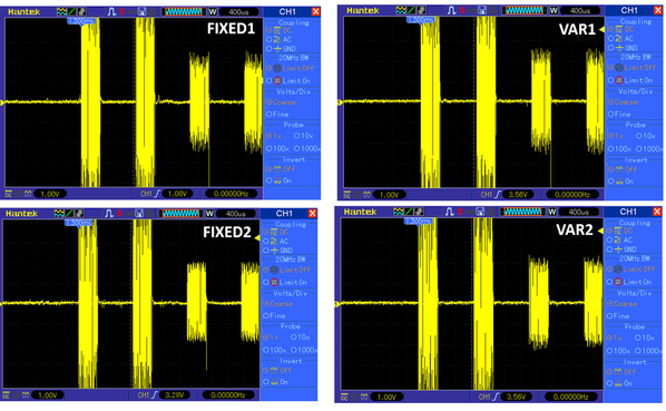
The measurement I do is to send some DCS packets out of each TIU output without it connected to the layout, and measure the DCS pk-to-pk excursion voltage like this:

DCS_measure

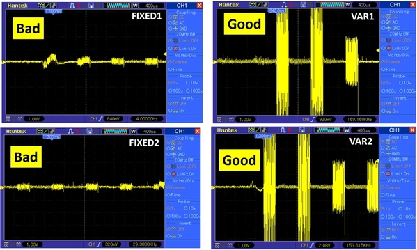
So typically out of the box new the DCS signal pk-pk excursion is about 15V. As we ran our layout we found some sections started to have poor control, then eventually no control. Investigating the DCS signals showed that the channels driving these sections suffered very low output DCS voltage (even when the TIU channel wasn't even connected to the layout). For example here is a TIU pulled out of the layout and measured on the bench with 2 bad channels:

BAD

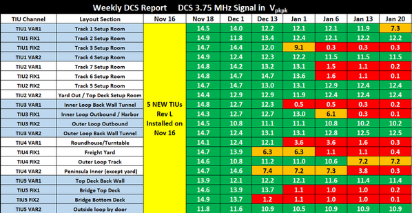
So at first we didn't really understand this too well. We weren't sure how long our layout was like this, and if the TIUs were defective from day 1 or not. On Nov 16 2017 we replaced all 5 TIUs in our club with brand new out of the Box "Rev L" TIUs. From that day on, each week I would measure each TIU channel 1 by 1 (Disconnected from the layout) and write down the excursion number.

Here is our actual log sheet:

DCS_status_1

As you can see from the measurements taken, we only lasted about 2-3 weeks before the DCS levels started dropping on the brand new modules. When we setup the 5 new TIUs on Nov 16 we also installed those PSX-AC units recommended to us by gunrunnerjohn and put the entire layout in passive mode. So that was 5 TIUs and 20 PSX-ACs (A substantial investment!).

After this disaster we decided we would reverse engineer the TIU to try and figure out the root cause of failure. There was a lot of swapping of SMD parts between good and bad channels but nothing really came of it until I talked to Jason W at MTH...


  ======== ROOT FAILURE ========

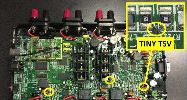
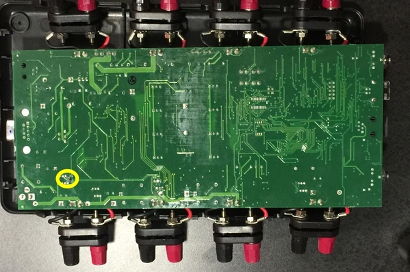
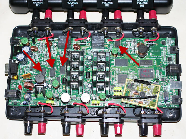
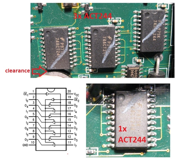
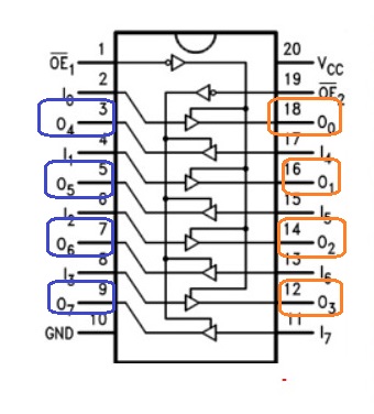
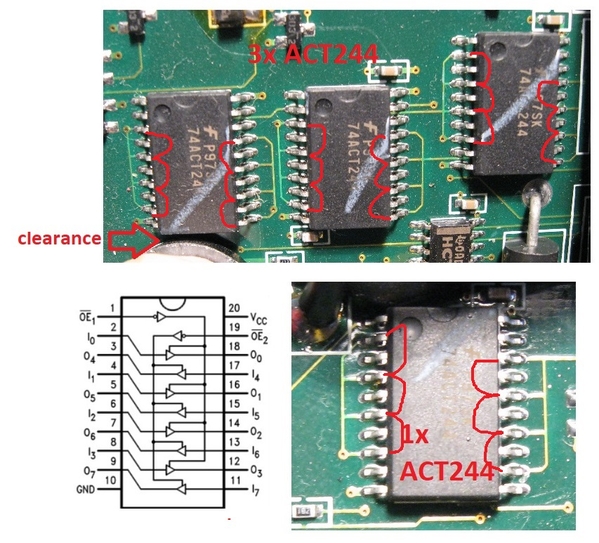
 So the reason we didn't catch the failure with all the swapping is becasue the failing part is well hidden and not actually on the PCB. Somewhere between the TIU rev where they laid out the PCB and the rev L that's sold today someone at MTH engineering decided to add teeny tiny SMD TSVs to protect the ACT244s, but there's no pads for them on the PCB, they are cleverly added to existing components.

Actually all of these tiny TSVs are hidden from plain sight. Var 1 is hidden under the output transformer, Fixed 1 is hidden under a heat-sink, Fixed 2 is on the back, and Var 2 is conspicuously soldered in parallel with another resistor.

TSV_locations

TSV_locations2

So the moment you un-solder these TSVs the signal excursion goes back to normal (although now your ACT244s aren't protected and if something happens you'll be replacing those instead).


All good again:

FreshTIU

I pulled the part number off these TSVs and replaced them, and yeah things worked for a few days (Jan 21,22,23), but then it failed again back to 0.1V (sad). So clearly it was just not a big enough TSV to handle either the peak currents or peak voltages that happen during train mishaps. Actually for some reason, running a lot of Lion Chief trains seems to really fail these diodes faster than MTH or other Lionel trains (maybe something about the motor inductance and peak inverse voltage.... who knows?).


  ======== THE FIX PART 1 ========

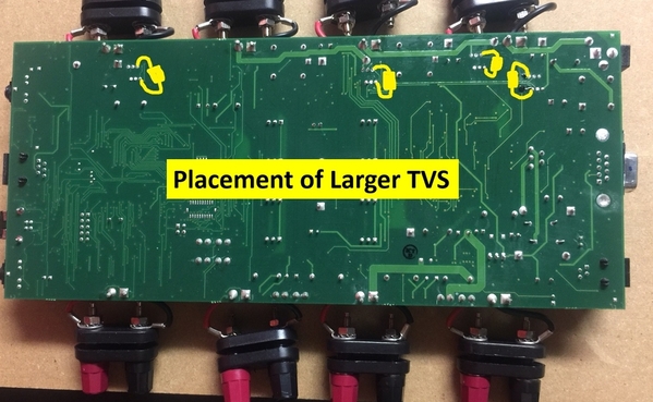
So the first thing we did is try to replace those sad SMD tiny TSVs with bigger ones. The MTH guys showed me other points on the PCB where we could "get at" the same nodes as the original TSV devices. Here is map of that. Sorry I didn't take a photo with the TSVS on when I had it open, and I don't want to open up a working one just to take a photo.... You guys are smart. I'm sure you get the point.

new_TSV_locations

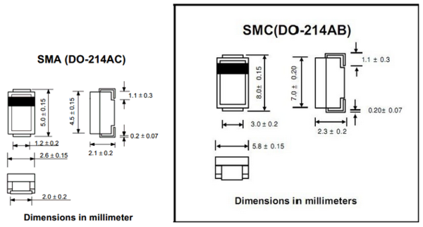
So the TSVs we ended up using are these ones (TSV device). So the idea was just solder them on there in those spots and you should be good to go. Note that TSVs come in 1 of two varieties (one diode and two diode). If you get the one diode one you only have unipolar protection so you need to solder two back to back to get bipolar suppression (yes it matters a lot actually).

We ran the layout like this for a little bit (Jan 24-29) and it mostly worked but we still had the odd failure (like 1-2 channels total). By destroying a few TSVs on the bench I found they don't like to sit in the clamped condition for too long or their clamp voltage starts to drop. With the PSX-ACs in there, that shouldn't happen, but I guess it did.


  ======== OUR CURRENT SOLUTION rev "M?" ========

So the thing about TSVs is they are zener based devices... so they are very fast but they don't like to continuously dissipate power. On the other hand basic rectifier diodes are not very fast switching devices, but they are happy to dissipate power (think rectifier bridge in a power supply) as long as you need. So the obvious design answer was to have two parallel clamps, a fast acting one, and a slower, but beefy one. It just so happens the 9.2V clamp voltage on the TSV is close to an integer multiple of the typical 1n4148 diodes used to support  EE100 lab classes across the country.

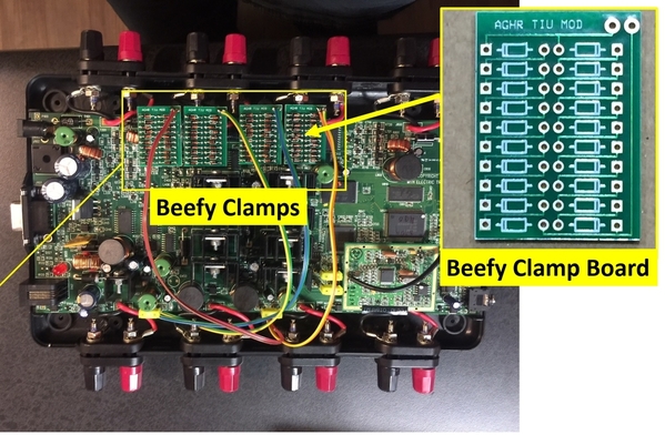
So what we did is build a little daughter board for each channel with two strings of parallel series diodes (up and down) that clamp at roughly 9.1V (about 0.7V X 13). We ran wire to the backside of the board and glued the daughter boards on top of the relays (they do fit, but barely). Since this is the "slow" clamp the wire inductance won't hurt you on the time constant. As I mentioned, we use a basic 1n4148 diode.


It looks like this when everything is in:

beef

  ======== RESULTS ========

I'm not 100% sure why the larger TVS devices are over-stressed but the parallel clamp seems to be working fine so far. While my friends bring trains to run, I bring my oscilloscope and probes to our club and just disconnect and measure each channel one-by-one week after week.


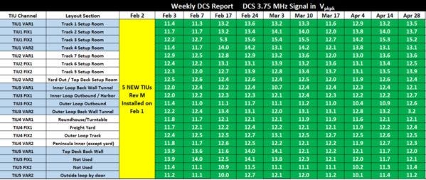
Since updating to this revision "M?" configuration on Feb 2 here are the measurements completed:

DCS_status_2

I've said it's solved 3 times now and been proven wrong, so at this point I'll just say, we've measured the DCS voltages weekly for almost 3 months, and seen no issues, so the evidence is leaning that way. I will continue to measure into the future, and will post if we do see a failure. So far so good though!


   ======== FINAL THOUGHTS ========

The SMD TSVs are so weak, and they fail to like 1-2 ohms across the ACT244 output. Even just a momentary short and you can loose 99% of your signal swing pretty much instantly. Since we put these new revisions in, you really don't get engine "not-on-track" or failure to add engines anymore. Track signals seem solid no matter how horrendous the actual wiring is. I'm sure this failure is a cause of grief for a lot of people besides just us. Of course if you don't have an oscillscope it's hard to tell.

Anyways, the smart MTH guys have all the details, the measurements, and even the PCB layout of my little daughter board, so I guess it's up to them how to proceed with it.


So yeah, if the TIU-train communications are lousy, check the hidden tiny TSVs.

Attachments

Images (9)
  • DCS_measure
  • BAD
  • DCS_status_1
  • TSV_locations
  • TSV_locations2
  • FreshTIU
  • new_TSV_locations
  • beef
  • DCS_status_2
Last edited by Adrian!
Original Post

Replies sorted oldest to newest

WOW  Looks like I'm going to be waiting on additional and upgrades to my TIU.  New requirement to be a model railroader, have a PhD in EE!!

My layout currently in the early stages gives the "Engine not on track" message sometime, even though they will run and I get the double toot all the time.  This with 4 120ft mains with 5 blocks each loop, 2 loops per fixed channel.  Granted I have an old rev H TIU that was given to me, but I am getting by.

Great investigation and hopefully MTH will bring Rev M out before I need to by another.  MTH, please put an outside antenna jack on as well.

As an aside, anyone starting with DCS needs to by Barry's book(s), they are invaluable and saved me some hair.  This forum is great also.

Gray Lackey


Those pesky TVS everyone likes to add to layout and devices, and low an below these short and you don't know it.  These where a fix for Rev L TIU to protect the transmitter.  Good to know.  So what I would love to know, is how long an Sans TVS Rev L or a Rev I last on your layout.  Another component to check when repairing TIUs. Thanks for posting. G

GGG posted:

Those pesky TVS everyone likes to add to layout and devices, and low an below these short and you don't know it.  These where a fix for Rev L TIU to protect the transmitter.  Good to know.  So what I would love to know, is how long an Sans TVS Rev L or a Rev I last on your layout.  Another component to check when repairing TIUs. Thanks for posting. G

Yeah they fail to short-condition because its a zener. If you were super careful you could just run without them, but the component taking the hits will be the ACT244 octal. It's beefier and has an ESD clamp on the chip die, but it's a much more painful thing to change since you need the hot air.

Last edited by Adrian!
David Minarik posted:

One other question:

When the TSV blows, is anything else down the line taken out because of this?

Thanks,

David Minarik posted:

Adrian,

Would this problem be the same in all or most REV TIUs or just REV Ls?

Thank you for posting this!


I haven't been in the hobby that long so I don't know when these TSVs made their debut. It looks recent. Others here probably know better than me.

Well, you don't really need hot air to change the ACT244, but I'll allow it's a lot harder to replace than the little TVS.  I simply cut all the legs off the old one right at the body, then sweep the remains of the legs off the pads with the iron, then position and solder the new chip on.

That's excellent work on the fix, and I'd have never imagined you could take out the 500W TVS so quickly across those parts.

Would you post a schematic of the diode PCB, I'd like to take a closer look at perhaps a more compact solution.  I use SMT diodes that would have similar characteristics as the 1N4148, it would be easy to do a more compact board.  Now that a solution is at hand, maybe there's a more compact clamping solution to be had, perhaps even other than multiple diodes.

One question arises, the diodes would only clamp in one direction, are you using two sets of them to clamp the bi-polar signal?

Last edited by gunrunnerjohn
gunrunnerjohn posted:

Well, you don't really need hot air to change the ACT244, but I'll allow it's a lot harder to replace than the little TVS.  I simply cut all the legs off the old one right at the body, then sweep the remains of the legs off the pads with the iron, then position and solder the new chip on.

That's excellent work on the fix, and I'd have never imagined you could take out the 1500W TVS so quickly across those parts.

Would you post a schematic of the diode PCB, I'd like to take a closer look at perhaps a more compact solution.  I use SMT diodes that would have similar characteristics as the 1N4148, it would be easy to do a more compact board.  Now that a solution is at hand, maybe there's a more compact clamping solution to be had, perhaps even other than multiple diodes.

One question arises, the diodes would only clamp in one direction, are you using two sets of them to clamp the bi-polar signal?

Hey,

I never did a schematic because it was too simple, I just drew it out-right. Compact 1n4148s would work but if time was spent you could find a rectifier with a higher drop so you wouldn't need so many.

Here's a doodle:

fig4

I tried both the bidirectional and unidirectional (two back to back, just like you're thinking) TVS diodes, but they're both pretty much the same IV characteristic. In the end the reason I went with the unipolar one for the complicated reason that they were in stock on digikey, while the bipolar ones were not.

The 1n4148s are two parallel strings up and down.


Attachments

Images (1)
  • fig4
Last edited by Adrian!

Oh yeah, other details:

1. In the original post I said 13 clamping diodes but it's really 10. It was 13 on the breadboard but 10 on the final PCB. I wanted the big clamp voltage a little lower than the small clamp voltage to try and get an early turn on.

2. If the original tiny TVS fails and sits that way for more than a few minutes (like a day) then the ACT244 is usually damaged too (since it's been sending commands to a short circuit instead of a train). So if you lift off the diodes and the swing doesn't come back, that's the next thing to look at.

OK, so a single diode board is used for one output, and you just have two diode strings back to back.  That's what I was wondering about.  I was thinking along the lines of a higher drop, or even some active circuit that didn't require so many components.  Also, it would probably all be put on one board with wiring to the appropriate places for all four channels.

I always start with a schematic as I'm too lazy to manually route, I just let the auto-router do that job.

Maybe three of these in each direction would do the clamping in a much more compact form?  Sanken EG01CV1, six instead of 22 diodes would be a lot easier to deal with.   I'm also not sure you need the TVS as well, I'd think these would do the trick.


Last edited by gunrunnerjohn
gunrunnerjohn posted:

OK, so a single diode board is used for one output, and you just have two diode strings back to back.  That's what I was wondering about.  I was thinking along the lines of a higher drop, or even some active circuit that didn't require so many components.  Also, it would probably all be put on one board with wiring to the appropriate places for all four channels.

I always start with a schematic as I'm too lazy to manually route, I just let the auto-router do that job.

Maybe three of these in each direction would do the clamping in a much more compact form?  Sanken EG01CV1, six instead of 22 diodes would be a lot easier to deal with.


Exactly!

Yeah those might work. The best thing to do is buy a handful and put them under full conduction for an hour and see if the knee voltage changes over time.


gunrunnerjohn posted:

You could also up the rating of the TVS slightly to insure the diodes are taking the heat if the response is too slow

Hey,


It’s tricky to drop the TVS devices...., rectifier diodes are a very soft IV so they are a gentle clamp, while TVS chop voltage like a straight line. You’d have to test to make sure you were turning on fast enough but not so early in excursion that you start chopping the dcs signal itself .... I bet you can get it with some fine tuning though.

also theres other speed considerations.... it’s a bit complicated but basically the TIU pcb has a ground and vdd plane so the traces on it look like microstrip lines (real part only... no jX) with low impedance terminations since the transformer and ACT244 outputs are low impedance.

Once you have a long umbical cable you start picking up inductance that can hurt your time constant. That’s the advantage of soldering the TVS right on the spot.

I only had to make 5 sets and it was a prototyping exercise so nothing was a final print .... but If I had to do 500 I’d probably do a very very low profile small area board like 0.5” x 0.5” with SMD diodes and have two vias on the back that solder directly to the points on the main pcb. That keeps the time constant up and reduces the labor per.

Again, you’re good at PCBs so I’m sure you could tighten it up a lot.


This is seems to be a Great Upgrade, MTH should incorporate this and an external antenna port, into a new Rev"M" TIU ASAP, and also develop an upgrade component for Techs, Thanks for all your work and persistance on this. I met Jason a few years ago, May have been in San Diego or Pasadena,  a good guy in the business. 

Thanks Again, RWDeano

A good idea to attach the PCB directly to the ACT244, it would probably not be too difficult to rig something that solders to the top side right on the chip to keep the leads short.  Then you could put the TVS and diodes on one board.  I'd have to do more research to see how this plays out.

I wonder if MTH is actually going to do something with this to prevent this issue.  I know the NJ-HR folks have had similar issues with their TIU's, this explains what is happening I suspect.

I've read this whole post and passing it on to our Electrical Engineer cub member. I know he will understand what you folks are talking about. We have too many witches brews on our layout trying to maintain a dependable "DCS" signal strength. This sounds like this guy figured out the fix.........Very much thank you for your perseverance, in coming to a resolve...

AlanRail posted:

Great for EEs. What do the rest of us do in the meantime??!

I see a small cottage industry for someone to fix TIUs Rev Ls ; I can't imagine MTH taking this on as a warranty repair.

Everything here is open to use as far as I’m concerned, I just want to help people avoid the problems I’ve been having. Maybe one of the professionals like GGG or gunrunnerjohn can do the mods for folks

its not expensive, maybe $10 a TIU in quantity. The pcb is more, but I only made 25 so a larger volume would benefit there too.

(or just “run” the trains without power)


Last edited by Adrian!
Ron_S posted:

A question from the peanut gallery, can the TVS be put between the power supply and the TIU?

Engineer-Joe posted:

anything we could put in front of the TIU to handle the spikes so this wouldn't occur?

It's not so simple actually. You want the TVS right up against whatever it's protecting:

There's a little bit of RF design principles here (sorry it's complicated)... let me try to explain it easily:

What happens when a train derails is the motor and bouncing contacts produce transient events (fast changing voltages and currents over a short time duration... like 1-10ns range). These transient events are short in time which means they are very wide-band in frequency (fourier transform describes this).

They can be up to the GHz range,  which means they behave like RF waves on the wiring and track (because they have a comparable wavelength in the 10s of inches regime). Once you are into this wave propagation behavior it means that the whole wire length is not the same voltage at the same time. So just because you null out the voltage at one point along the wire with the TVS between the train and the TIU doesn't mean the transient voltage at the TIU or train is zero because of the waves bouncing up and down the wire.

If you want the basics it's here: Transmission lines

So the only way to be 100% sure the transient voltage at the protected device is safely held down by the TVS is to physically place it very close to the thing your protecting (like within 1/10th of a wavelength). That's why it has to go right on the board inside the TIU.

Hope that wasn't too poorly explained!

Adrian! posted:
Ron_S posted:

A question from the peanut gallery, can the TVS be put between the power supply and the TIU?

Engineer-Joe posted:

anything we could put in front of the TIU to handle the spikes so this wouldn't occur?

It's not so simple actually. You want the TVS right up against whatever it's protecting:

There's a little bit of RF design principles here (sorry it's complicated)... let me try to explain it easily:

What happens when a train derails is the motor and bouncing contacts produce transient events (fast changing voltages and currents over a short time duration... like 1-10ns range). These transient events are short in time which means they are very wide-band in frequency (fourier transform describes this).

They can be up to the GHz range,  which means they behave like RF waves on the wiring and track (because they have a comparable wavelength in the 10s of inches regime). Once you are into this wave propagation behavior it means that the whole wire length is not the same voltage at the same time. So just because you null out the voltage at one point along the wire with the TVS between the train and the TIU doesn't mean the transient voltage at the TIU or train is zero because of the waves bouncing up and down the wire.

If you want the basics it's here: Transmission lines

So the only way to be 100% sure the transient voltage at the protected device is safely held down by the TVS is to physically place it very close to the thing your protecting (like within 1/10th of a wavelength). That's why it has to go right on the board inside the TIU.

Hope that wasn't too poorly explained!

Previous advice seen here: TVS placed across the TIU output(s) does the trick, yes/no?

Kerrigan posted:
Adrian! posted:
Ron_S posted:

A question from the peanut gallery, can the TVS be put between the power supply and the TIU?

Engineer-Joe posted:

anything we could put in front of the TIU to handle the spikes so this wouldn't occur?

It's not so simple actually. You want the TVS right up against whatever it's protecting:

There's a little bit of RF design principles here (sorry it's complicated)... let me try to explain it easily:

What happens when a train derails is the motor and bouncing contacts produce transient events (fast changing voltages and currents over a short time duration... like 1-10ns range). These transient events are short in time which means they are very wide-band in frequency (fourier transform describes this).

They can be up to the GHz range,  which means they behave like RF waves on the wiring and track (because they have a comparable wavelength in the 10s of inches regime). Once you are into this wave propagation behavior it means that the whole wire length is not the same voltage at the same time. So just because you null out the voltage at one point along the wire with the TVS between the train and the TIU doesn't mean the transient voltage at the TIU or train is zero because of the waves bouncing up and down the wire.

If you want the basics it's here: Transmission lines

So the only way to be 100% sure the transient voltage at the protected device is safely held down by the TVS is to physically place it very close to the thing your protecting (like within 1/10th of a wavelength). That's why it has to go right on the board inside the TIU.

Hope that wasn't too poorly explained!

Previous advice seen here: TVS placed across the TIU output(s) does the trick, yes/no?

Maybe..... The plastic terminals are still a few inches away from the octal driver chips that are being protected. Also the PCB isn’t made of air so the wavelength is even shorter.

you can try it and see. The catch is you’ll need an oscilloscope and weeks of measurements to validate if it’s actually fixed or not.

That’s the part I can’t emphasize enough actually.... this has been more like a clinical trial than a design check. You never know what’s going to happen in the club so you have to measure over a long period to validate everything is okay. Adjusting the TIU is trivial ...but lugging the scope under the table with an extension cord and disconnecting the layout channels one by one for 5 TIUs and measuring signals is like a 1 hour start to every club visit.

The TVS on the output of the TIU is a much higher value than needed to protect the 244 signal driver chip, those TVS chips are 9V rating.  Also, Adrian said what I've said about the TVS across the power supply when protecting the electronics in the engine.  That's good, but having it right across the engine pickups in the engine and close to the actual electronics is simply better.

In the case of the TIU signal generators, I was looking at what could be done to make the protection boards more compact.  I wonder if two back-to-back 8V Zener diodes and the 9V TVS would be a good solution.  The exact Zener voltage could be "tuned" to balance the protection for the TVS so it doesn't have to absorb the power of a longer surge.  The TVS will do the initial suppression, and if the spike lasts long enough, the Zener diodes carry the load.  This would seem to be similar in concept to the diode arrays, but a far lower parts count.  It might be possible to get the board size down to a very compact little board with a small enough parts count.  I'm thinking about .3" x .5" or so.  This kind of board could really sit right on top of the 244 chip and just solder directly to the leads.  It would be easy to install, and there's tons of clearance on the top of the TIU circuit board.

Last edited by gunrunnerjohn

Thanks Adrian....I was able to understand just enough of this to see that you have likely hit on a permanent solution for DCS signal degradation.  I'm running out of good channels here. 

Could I possibly be smelling ozone over at GRJ's workbench as he conjures up some sister boards for public consumption?  One ERR door closes and another opens.

Bruce

Adrian,

Our club has a conglomerate of knowledge, but this has opened a new channel to help remedy the degradation of the signals, and that dreaded "Engine not on the tracks" readout. We run 5 TIU's with scads of AIU's for the layout. 


GRJ, Will the fix your contemplating blend with the TMCC booster to make both systems better?

Honestly, my thinking:

I know this sounds a little bit out there... but I think if a club is willing to spend $1000 on TIUs, probably $1000 on remotes, $500 WIUs, and maybe another $500 on power supplies, plus maybe another $1500 on Legacy/TMCC support and like who knows how much on the trains themselves...., then it makes sense to spend $250 to get a good club oscilloscope to debug the DCS setup. If you don't know how to do that, you can watch a 12 minute youtube video on how to make the measurements. Heck, if there's interest I can even make the tutorial video and post it here. I think if you learned how to change train tires, replace a smoke unit, or wire up a layout, then the signal measurements aren't really that much more to know. It took me 1 hour to change a tire yesterday.

I've found trying to troubleshoot DCS without looking at the signal on the scope isn't effective, it either works, or doesn't work. Different trains behave a little different. You can't really separate the RF link issues from the track signal issues and everything is very anecdotal ("my train does this but when I do that it does that"). I always think it's better to attack this stuff analytically with measurements. Short CDMA exchanges like horns need about 5-6V to be decoded successfully. Long CDMA exchanges like adding engines need about 10V to decode. Once you drop scope probes and measure you know exactly what's going on. Also I like having it disconnected from the layout so it's not influenced by who's train is where and what amount of track is on each channel. It's just a simple direct assessment of the circuit performance.


I certainly admire all of you folks that have the patience and knowledge to stick with these things and then actually find a solution! WE are very lucky to have you all here on the OGR forum to help the rest of us (me anyway) lesser qualified folks that still like to try and keep up. It also helps the rest of us (again, me anyway) at least learn a little bit about some of these things. And I enjoy following along even if it is all over my head.

Thanks for all your efforts and please continue!! This was a neat discovery that I'm sure will help many people in the hobby.

I remember Ben at the NJ highrailers was telling me that when they first got the REV L TIU they were blowing them up left and right. They gave up on the L and went with older models.  Wonder if this is the same issue.  Correct me if I’m wrong NJ?

is this a issue with only larger layouts with large power supplies?  Knock on wood, no issues wth my REV L TIU.

Well, Adrian's fix certainly seems to hold out promise for TIU signal degradation, and the TMCC Booster should do good things for TMCC/Legacy, so I guess the answer would be yes.

I'm waiting on Adrian's take on my latest idea, I think the standard Zener diodes should work, they're used in continuous service for power supplies, so they ought to handle a longer spike.

Adrian! posted:

The TVS are after the transformers where the power and digital signal are split up, so TMCC/Legacy systems won't even notice them in the system.

Maybe it would be easier to lift off the ACT244 and put the adjusted board underneath between it and the main board.

An interesting thought.  I'd just buy new ACT244's and build the boards, then arrange for the board to be soldered to the pads.  There are some neat adapters that would solder onto the main board and you could plug the adapter with the ACT244 and the diodes and TVS on them into the adapter.  If any issue arose with signal generation, plug in a new daughter board.  Interesting thought...

New Haven Joe posted:

I am confused.  Are you saying that a failed TVS degrades the DCS signal and that by replacing the TVS or replacing the TVS with your new board fixes the DCS signal problem?

 Or, are you saying that the failed TVS has allowed the DCS signal transmitter to become fried?  The fix is to replace both the signal board and the TVS.

NH Joe

The TVS is supposed to protect the DCS transmitter (ACT244) but when it fails it shorts the DCS transmitter output so nothing comes out the TIU port. If it stays like this too long it kills the ACT244 itself

superwarp1 posted:

I remember Ben at the NJ highrailers was telling me that when they first got the REV L TIU they were blowing them up left and right. They gave up on the L and went with older models.  Wonder if this is the same issue.  Correct me if I’m wrong NJ?

is this a issue with only larger layouts with large power supplies?  Knock on wood, no issues wth my REV L TIU.

Just like us. That’s how this all started. 14 TIUs in 2 months. I get it’s the same problem. It really has not much to do with the layout, more about how rough you are on it.

gunrunnerjohn posted:
Adrian! posted:

The TVS are after the transformers where the power and digital signal are split up, so TMCC/Legacy systems won't even notice them in the system.

Maybe it would be easier to lift off the ACT244 and put the adjusted board underneath between it and the main board.

An interesting thought.  I'd just buy new ACT244's and build the boards, then arrange for the board to be soldered to the pads.  There are some neat adapters that would solder onto the main board and you could plug the adapter with the ACT244 and the diodes and TVS on them into the adapter.  If any issue arose with signal generation, plug in a new daughter board.  Interesting thought...

The zeners should work if you get the turn on voltage just right. You might want to test a bit. One thing to remember is the voltage varies a bit from part to part on the ACT244s so Yu don’t want to be clipping their outputs. I found soft turn on around 8-9V and hard turn on about 9.2-9.5V covers all the cases I’ve seen. Just make sure the zener you pick is 1 ns range recovery time.

You could even do a daughter board with the 244 on a socket for quick changes if something ever goes wrong later.

Adrian, with reference to your post above about a club that spends all those $$ should be willing to buy and use an oscilloscope.  I am not in a club, and $250 would stretch a bit, but can you recommend an oscilloscope that a reasonably proficient person could, with a little research learn to use for this purpose?

Can these also be used with the tiu attached to the layout?  I wonder if it would help to to discover spurious signals that cause the Doubletoot Syndrome?

RJR posted:

Adrian, with reference to your post above about a club that spends all those $$ should be willing to buy and use an oscilloscope.  I am not in a club, and $250 would stretch a bit, but can you recommend an oscilloscope that a reasonably proficient person could, with a little research learn to use for this purpose?

Can these also be used with the tiu attached to the layout?  I wonder if it would help to to discover spurious signals that cause the Doubletoot Syndrome?

The one I linked in that post is about the cheapest one that can see the dcs waveform reliably. In terms of use its not that hard once you understand how to trigger properly. I can do a post on that later.

You can certainly sense the signals when connected to the layout and it’s helpful for all kinds of debugging.


When the TIU is connected to the layout the signal voltage depends on the number of engines on the track and types and such.... so when testing the TIUs themselves I disconnect them so the test conditions are identical week to week


The other thing is, there may be a bit more leeway in picking values.  It's quite possible that you could get away with different values for the spike suppression and still protect the drivers sufficiently.  After all, the voltage amplitude is a big driver here, the higher the amplitude, the more energy that would be hammering on the 244's.

I think this would have to be tested in a high traffic club layout to really zero in on the ideal solution.

In thinking about the outputs of the ACT244, there's no reason that the output should go significantly below ground, AAMOF, that's probably bad for the chip.  That being the case, it might makes sense to try to clamp the output from going below ground and just deal with the positive swing.  The absolute highest voltage the outputs should see, at least according to the data sheet is a supply voltage of +7VDC, and the output shouldn't ever exceed VCC by any major amount.

I don't know much about the circuit in the TIU, but my understanding is the four outputs of the ACT244 are paralleled to drive the signal injection transformer for the DCS signal.  In looking at your scope signal, that's clearly not right on the ACT244, but rather looks to be on the other side of the signal transformer.  However, we're trying to nail the surges at the ACT244 gates directly, right?  Maybe the clamping can be a bit different, given the limits that the part is supposed to tolerate.  Truthfully, the ACT244 isn't really designed to be an analog driver, probably why it doesn't excel at the task.

I'm just wondering if there isn't a much simpler solution here.  As far as the TVS, how about forgetting the silicon diodes and just putting one of the big honkin' 3kw TVS diodes right across the gates and dispense with the diodes.  It'll take a much bigger beating than the 500W ones that you were testing with, and with the adapter board, it should be easy to piggyback on the existing ACT244.  I'm thinking of something like this Littlefuse SMDJ7.0CA.  Hard to believe it couldn't stand up to a fair amount of punishment.  It's small enough to perch right on top of the ACT244 on a little PCB.


Last edited by gunrunnerjohn

Adrian,


First, let me say Thanks for all the hard work you have put in to figure out what is happening! Not to mention your clear- to- the - layman explanations. I get it, or at least enough to appreciate what you have done and follow along with what you and GRJ are discussing. (Dang! That's scary!)

You posted this earlier regarding o-scopes:

Heck, if there's interest I can even make the tutorial video and post it here.

Heck, YES! I'm interested. In fact, I have an o-scope and just need to learn how to properly use it. I'll post make and model a little later. So carry on! I will keep watching and learning.

Chris

LVHR

Last edited by lehighline

Adrian, I've been getting some of our club members to read this post, as we ongoingly have to crawl around under the layout and use some sort of little lights that are suppose to fix all of the Woes of the MTH TIU Signal strength. Everytime that we take the layout apart to take to another train show there is always some sort of VooDoo that we have to do. It sure isn't a plug and play...From what I've read on your post you have take the time out of your busy, and did the troubleshooting and found the fix. Maybe Gunny will come up with some sort of board or whatever to make the fix simple for us simple people. I myself like Plug and Play, not Reinventing the **** wheel everytime I want to run trains. Our resident Electrical Engineer has done a great job in making what we have better, but it's a long way from the old Lionel TMCC , and now with Gunny John going to make a Signal Booster for the TMCC/Legacy that should put all of the planets in alignment. I commend you sir for your efforts and resolve..........................................................Eric Brandenburg

If you build this board build in a LED light that illuminates when the TVS Shorts.  While the design is meant to prevent the TVS shorting rapidly, I am sure after enough hits even the new one will short.  Since it doesn't show up as a power short, like the input/output TVS, but will degrade DCS signal (which might not be detected on a small layout) a LED would be nice.  It must be serviceable easily also.

Lastly, there are plenty of REV L TIU out there with out this TVS mod form MTH.  Therefore your TIU is not susceptible to this exact failure.  Your failure will be the Transmitter chip. 

Most people do not have the issues this San Diego club has.  I have repaired plenty and they have not come back.  Frankly, I probably only worked on a few (less than 5), that had the TVS mod.

So the sky is not falling.  But this mod may make the Rev L TIU much more robust.  G

GGG posted:

If you build this board build in a LED light that illuminates when the TVS Shorts.  While the design is meant to prevent the TVS shorting rapidly, I am sure after enough hits even the new one will short.  Since it doesn't show up as a power short, like the input/output TVS, but will degrade DCS signal (which might not be detected on a small layout) a LED would be nice.  It must be serviceable easily also.

Lastly, there are plenty of REV L TIU out there with out this TVS mod form MTH.  Therefore your TIU is not susceptible to this exact failure.  Your failure will be the Transmitter chip. 

Most people do not have the issues this San Diego club has.  I have repaired plenty and they have not come back.  Frankly, I probably only worked on a few (less than 5), that had the TVS mod.

So the sky is not falling.  But this mod may make the Rev L TIU much more robust.  G

not sure you have the correct club mentioned.

ADRIAN! is from the angels gate Hi-railers which is outside long beach calif.

However the san diego 3 railers is having the same issue.

bigdodgetrain posted:

very interesting that "MTHRD" has not responded.


if our trains would have such an issue we would demand the manufacture take it back and fix it.

why can't MTH take the TIU's back and fix them???

So the thing is MTH makes great trains that generally run very well. There's no way you can expect them to find this because unless you have a club full of people and trains coming and going and derailing over and over week after week, how would you even know it's an issue? So far it takes like 1-2 weeks before these TVS diodes even start to fail in our club, and MTH has a business to run and parts to repair so it's not like they can sit there and run trains for weeks on end doing robustness tests. I'm glad I was able to help them out with that so we all benefit.

At the same time, we have a big club, and a lot of junior users that are a bit hard on the layout so we have a real problem with the TVS devices dropping out (and I'm sure other clubs are similar) so we needed a solution. Now we have an understanding of the problem, a way to detect/diagnose it, and a solution (with GRJ and others thinking about taking the work done so far and making it better). Everyone has access to this detailed write up and history of the thoughts so far. What could be better?

gunrunnerjohn posted:

The other thing is, there may be a bit more leeway in picking values.  It's quite possible that you could get away with different values for the spike suppression and still protect the drivers sufficiently.  After all, the voltage amplitude is a big driver here, the higher the amplitude, the more energy that would be hammering on the 244's.

I think this would have to be tested in a high traffic club layout to really zero in on the ideal solution.

In thinking about the outputs of the ACT244, there's no reason that the output should go significantly below ground, AAMOF, that's probably bad for the chip.  That being the case, it might makes sense to try to clamp the output from going below ground and just deal with the positive swing.  The absolute highest voltage the outputs should see, at least according to the data sheet is a supply voltage of +7VDC, and the output shouldn't ever exceed VCC by any major amount.

I don't know much about the circuit in the TIU, but my understanding is the four outputs of the ACT244 are paralleled to drive the signal injection transformer for the DCS signal.  In looking at your scope signal, that's clearly not right on the ACT244, but rather looks to be on the other side of the signal transformer.  However, we're trying to nail the surges at the ACT244 gates directly, right?  Maybe the clamping can be a bit different, given the limits that the part is supposed to tolerate.  Truthfully, the ACT244 isn't really designed to be an analog driver, probably why it doesn't excel at the task.

I'm just wondering if there isn't a much simpler solution here.  As far as the TVS, how about forgetting the silicon diodes and just putting one of the big honkin' 3kw TVS diodes right across the gates and dispense with the diodes.  It'll take a much bigger beating than the 500W ones that you were testing with, and with the adapter board, it should be easy to piggyback on the existing ACT244.  I'm thinking of something like this Littlefuse SMDJ7.0CA.  Hard to believe it couldn't stand up to a fair amount of punishment.  It's small enough to perch right on top of the ACT244 on a little PCB.


Uh some details. The scope is looking at the output side of the transformer, not the waveform right at the clamping device/ACT244 driver output pins. Clamping from 0 to 7 volts could work but again it's got to be quick quick quick. A small zener or TVS is faster than a big zener since Cj is the dominant term in the time constant which grows with anode area.

Maybe a small TVS in parallel with a big TVS?

GGG posted:

If you build this board build in a LED light that illuminates when the TVS Shorts.  While the design is meant to prevent the TVS shorting rapidly, I am sure after enough hits even the new one will short.  Since it doesn't show up as a power short, like the input/output TVS, but will degrade DCS signal (which might not be detected on a small layout) a LED would be nice.  It must be serviceable easily also.

Lastly, there are plenty of REV L TIU out there with out this TVS mod form MTH.  Therefore your TIU is not susceptible to this exact failure.  Your failure will be the Transmitter chip. 

Most people do not have the issues this San Diego club has.  I have repaired plenty and they have not come back.  Frankly, I probably only worked on a few (less than 5), that had the TVS mod.

So the sky is not falling.  But this mod may make the Rev L TIU much more robust.  G

Hi there,

I thought about this too....

Doing a LED that illuminates when the TVS shorts is not easy since under normal condition there is sometimes no voltage there.

Think about the Thevnin equivalent..... when the ACT244 driver is outputting a "0" the voltage across the TVS is 0V, the same condition as when it fails.... so you would need to distinguish the two conditions from each other.  The only way to do this is the TVS current:

Normal 0   TVS voltage 0V   TVS current 0mA

Normal 1   TVS voltage 7V   TVS current 0mA

Fail          TVS voltage 0V   TVS current high

So you'd have to put something in series (a current sensing resistor) which isn't so simple. First you need to make the resistor big enough that you can develop a sensing voltage you can collect with a diff amp, but that resistor itself defeats the protective action of the TVS since you're adding an RC pole at Rsense X Cj and increasing the turn on time.

I think a better way is to build something that senses the channel outputs with a high-pass filter, maybe about a 100 KHz cutoff frequency (so it only looks at the DCS signal). Then use some type of hysteresis comparator and digital latch to see if you are exceeding 7V  occasionally. A good way is a 1-shot timer circuit. So everytime you see >7V... you trigger a one-shot that flashes the led for maybe 1 second. That way every-time a packet goes by, you get a LED flash. If the DCS excursion voltage is too low.... then the LED stops flashing.


I don't know about anywhere else so I can't speak to how common the TVS devices are, or how often they fail outside our club, but from what I've measured at least in my club, low DCS excursion is the root cause for almost all of our control problems. Some members have brought Rev L TIUs from home recently bought and installed and I've found the same TVS failing also.


bigdodgetrain posted:
GGG posted:

If you build this board build in a LED light that illuminates when the TVS Shorts.  While the design is meant to prevent the TVS shorting rapidly, I am sure after enough hits even the new one will short.  Since it doesn't show up as a power short, like the input/output TVS, but will degrade DCS signal (which might not be detected on a small layout) a LED would be nice.  It must be serviceable easily also.

Lastly, there are plenty of REV L TIU out there with out this TVS mod form MTH.  Therefore your TIU is not susceptible to this exact failure.  Your failure will be the Transmitter chip. 

Most people do not have the issues this San Diego club has.  I have repaired plenty and they have not come back.  Frankly, I probably only worked on a few (less than 5), that had the TVS mod.

So the sky is not falling.  But this mod may make the Rev L TIU much more robust.  G

not sure you have the correct club mentioned.

ADRIAN! is from the angels gate Hi-railers which is outside long beach calif.

However the san diego 3 railers is having the same issue.

Yup I'm from the angel's gate Hi-railers' club in San Pedro. It's like a big test-bench.  At one time I thought about joining the San Diego club but don't tell anyone though.

Adrian! posted:
bigdodgetrain posted:
GGG posted:

If you build this board build in a LED light that illuminates when the TVS Shorts.  While the design is meant to prevent the TVS shorting rapidly, I am sure after enough hits even the new one will short.  Since it doesn't show up as a power short, like the input/output TVS, but will degrade DCS signal (which might not be detected on a small layout) a LED would be nice.  It must be serviceable easily also.

Lastly, there are plenty of REV L TIU out there with out this TVS mod form MTH.  Therefore your TIU is not susceptible to this exact failure.  Your failure will be the Transmitter chip. 

Most people do not have the issues this San Diego club has.  I have repaired plenty and they have not come back.  Frankly, I probably only worked on a few (less than 5), that had the TVS mod.

So the sky is not falling.  But this mod may make the Rev L TIU much more robust.  G

not sure you have the correct club mentioned.

ADRIAN! is from the angels gate Hi-railers which is outside long beach calif.

However the san diego 3 railers is having the same issue.

Yup I'm from the angel's gate Hi-railers' club in San Pedro. It's like a big test-bench.  At one time I thought about joining the San Diego club but don't tell anyone though.

if you fix our issue I will make you a deal you can not pass up!

Adrian! posted:
bigdodgetrain posted:

very interesting that "MTHRD" has not responded.


if our trains would have such an issue we would demand the manufacture take it back and fix it.

why can't MTH take the TIU's back and fix them???

So the thing is MTH makes great trains that generally run very well. There's no way you can expect them to find this because unless you have a club full of people and trains coming and going and derailing over and over week after week, how would you even know it's an issue? So far it takes like 1-2 weeks before these TVS diodes even start to fail in our club, and MTH has a business to run and parts to repair so it's not like they can sit there and run trains for weeks on end doing robustness tests. I'm glad I was able to help them out with that so we all benefit.

At the same time, we have a big club, and a lot of junior users that are a bit hard on the layout so we have a real problem with the TVS devices dropping out (and I'm sure other clubs are similar) so we needed a solution. Now we have an understanding of the problem, a way to detect/diagnose it, and a solution (with GRJ and others thinking about taking the work done so far and making it better). Everyone has access to this detailed write up and history of the thoughts so far. What could be better?

"what could be better"

the issue fixed.


lehighline posted:

Adrian,


First, let me say Thanks for all the hard work you have put in to figure out what is happening! Not to mention your clear- to- the - layman explanations. I get it, or at least enough to appreciate what you have done and follow along with what you and GRJ are discussing. (Dang! That's scary!)

You posted this earlier regarding o-scopes:

Heck, if there's interest I can even make the tutorial video and post it here.

Heck, YES! I'm interested. In fact, I have an o-scope and just need to learn how to properly use it. I'll post make and model a little later. So carry on! I will keep watching and learning.

Chris

LVHR

A good start would be this very old post.A second one with a lot of useful details is this post where other people performed the same measurement.

Depending how deep you want to go into DCS there's a lot of other posts I've put up over the last year or so with all the ugly details


This tutorial describes the encode/decode process: DCS packet format

This tutorial describes how to capture DCS packets:  DCS Capture

This tutorial describes how to transmit: DCS_transmit

This is a more analytical one that fully describes the track signal between the train and the TIU in exact detail (I think no one reads this stuff):  DCS signal

bigdodgetrain posted:
Adrian! posted:
bigdodgetrain posted:
GGG posted:

If you build this board build in a LED light that illuminates when the TVS Shorts.  While the design is meant to prevent the TVS shorting rapidly, I am sure after enough hits even the new one will short.  Since it doesn't show up as a power short, like the input/output TVS, but will degrade DCS signal (which might not be detected on a small layout) a LED would be nice.  It must be serviceable easily also.

Lastly, there are plenty of REV L TIU out there with out this TVS mod form MTH.  Therefore your TIU is not susceptible to this exact failure.  Your failure will be the Transmitter chip. 

Most people do not have the issues this San Diego club has.  I have repaired plenty and they have not come back.  Frankly, I probably only worked on a few (less than 5), that had the TVS mod.

So the sky is not falling.  But this mod may make the Rev L TIU much more robust.  G

not sure you have the correct club mentioned.

ADRIAN! is from the angels gate Hi-railers which is outside long beach calif.

However the san diego 3 railers is having the same issue.

Yup I'm from the angel's gate Hi-railers' club in San Pedro. It's like a big test-bench.  At one time I thought about joining the San Diego club but don't tell anyone though.

if you fix our issue I will make you a deal you can not pass up!

I think step one is to establish that weak signals really are the issue you are experiencing. San Diego is not *so far* so maybe I can pay a visit with my test gear and have a look for you. The TIU you have is a Rev L with the USB port on the side right?

Adrian! posted:

So the thing is MTH makes great trains that generally run very well. There's no way you can expect them to find this because unless you have a club full of people and trains coming and going and derailing over and over week after week, how would you even know it's an issue?.... I'm glad I was able to help them out with that so we all benefit.

....Now we have an understanding of the problem, a way to detect/diagnose it, and a solution (with GRJ and others thinking about taking the work done so far and making it better). Everyone has access to this detailed write up and history of the thoughts so far. What could be better?

You have done an excellent job with this bit of problem identification and solving, Adrian! It's all way above my head, but I have truly enjoyed reading this thread and learning about how you approached both the problem and the solution. Very nice work!

So  MTH designed,  manufactured, and sold a device that self-destructs over a short period of time,  intentional or planned obsolescence.   but I dont see product liability as there is no resulting personal injury or property damage.

however I do see a whole lot of bad press unless MTH RECALLS ALL TIUs Rev L and fixes them.

Last edited by AlanRail
AlanRail posted:

So  MTH designed,  manufactured, and sold a device that self-destructs over a short period of time,  intentional or planned obsolescence.   but I dont see product liability as there is no resulting personal injury or property damage.

however I do see a whole lot of bad press unless MTH RECALLS ALL TIUs Rev L and fixes them.

Come on, this is not even a reasonable statement.  Go back and read what was said, a large club with heavy and hard use with constant derailments and shorts.  Causing degradation over a few weeks.  Not your average home layout.  G


Allan Miller posted:
Adrian! posted:

So the thing is MTH makes great trains that generally run very well. There's no way you can expect them to find this because unless you have a club full of people and trains coming and going and derailing over and over week after week, how would you even know it's an issue?.... I'm glad I was able to help them out with that so we all benefit.

....Now we have an understanding of the problem, a way to detect/diagnose it, and a solution (with GRJ and others thinking about taking the work done so far and making it better). Everyone has access to this detailed write up and history of the thoughts so far. What could be better?

You have done an excellent job with this bit of problem identification and solving, Adrian! It's all way above my head, but I have truly enjoyed reading this thread and learning about how you approached both the problem and the solution. Very nice work!

I'm with Allan.  Although not totally over my head I do enjoy seeing others make the hobby better!

Adrian! posted:

 .........Some members have brought Rev L TIUs from home recently bought and installed and I've found the same TVS failing also.

1.  Well, GGG, he also wrote the above.  You don't suppose those members let children play on those home layouts, do you ?

2.  If prolonged shorts are the 244 killer, wouldn't the best "control" test be Rev L boards with no [ 244 ] TVS protection BUT the newly purchased front end units [ PSX-AC ] that GRJ recommended ?  I don't he tried that combination.

SZ

Last edited by Steinzeit
Steinzeit posted:
Adrian! posted:

 .........Some members have brought Rev L TIUs from home recently bought and installed and I've found the same TVS failing also.

1.  Well, GGG, he also wrote the above.  You don't suppose those members let children play on those home layouts, do you ?

2.  If prolonged shorts are the 244 killer, wouldn't the best "control" test be Rev L boards with no [ 244 ] TVS protection BUT the newly purchased front end units [ PSX-AC ] that GRJ recommended ?  I don't he tried that combination.

SZ

Hey there!

If you read back from the start we mentioned the setup with the TVS failures had PSX-ACs installed on each and every channel. They're digital on a 20MHz clock so they aren't really that fast (50ns ish). The TVS themselves clamp on the order of 1ns depending on lead inductance.


Adrian! posted:
Steinzeit posted:

If you read back from the start we mentioned the setup with the TVS failures had PSX-ACs installed on each and every channel.

Well, I had read this thread from the start.   As I understand it, you installed the PSX units on Nov 16th at the same time as a new group of ex-factory Rev L 's were installed.  But you've never operated any channel as I've described as I understand your posts;  that is, PSX + non-TVS L's -- have you ?

SZ

Adrian, did you see my suggestion to simply use a 3000W TVS and eliminate the diodes?  I wonder if that would be robust to make this a "one component" solution?  After all, there can't be that much energy constantly bombarding the 244's, or they'd be failing all over the world.  As George points out, while we do see them failing, it's not a avalanche of them as a rule.  I'm just wondering if the part was robust enough, it would absorb whatever punishment was being dished out by the signal transformer kicking back to the 244's.

Adrian! posted:
gunrunnerjohn posted:

I'm just wondering if there isn't a much simpler solution here.  As far as the TVS, how about forgetting the silicon diodes and just putting one of the big honkin' 3kw TVS diodes right across the gates and dispense with the diodes.  It'll take a much bigger beating than the 500W ones that you were testing with, and with the adapter board, it should be easy to piggyback on the existing ACT244.  I'm thinking of something like this Littlefuse SMDJ7.0CA.  Hard to believe it couldn't stand up to a fair amount of punishment.  It's small enough to perch right on top of the ACT244 on a little PCB.


Uh some details. The scope is looking at the output side of the transformer, not the waveform right at the clamping device/ACT244 driver output pins. Clamping from 0 to 7 volts could work but again it's got to be quick quick quick. A small zener or TVS is faster than a big zener since Cj is the dominant term in the time constant which grows with anode area.

Maybe a small TVS in parallel with a big TVS?

I missed this in all the responses.   That's not a bad idea, I think I'd make the small TVS just a bit higher in voltage so that when the big one did clamp, it takes the stress off the smaller one.  What do you think, a 500W one like you used and the 3000W one?

Any chance you could equip one of your TIU's with this combo since you have the ideal testbed?  Or, maybe we can get Bob at NJ-HR to try this fix.  If we can come up with a working fix that only has a couple of components, it would be easy to make the piggy-back board that could be plopped on top of the 244's.

I checked the 3000W one I specified, it has a pretty decent response time, and the added capacitance of the little board should be minimal if we do it right.

Fast response time: typically less than 1.0ps from 0V to BV min

gunrunnerjohn posted:
Adrian! posted:
gunrunnerjohn posted:

I'm just wondering if there isn't a much simpler solution here.  As far as the TVS, how about forgetting the silicon diodes and just putting one of the big honkin' 3kw TVS diodes right across the gates and dispense with the diodes.  It'll take a much bigger beating than the 500W ones that you were testing with, and with the adapter board, it should be easy to piggyback on the existing ACT244.  I'm thinking of something like this Littlefuse SMDJ7.0CA.  Hard to believe it couldn't stand up to a fair amount of punishment.  It's small enough to perch right on top of the ACT244 on a little PCB.


Uh some details. The scope is looking at the output side of the transformer, not the waveform right at the clamping device/ACT244 driver output pins. Clamping from 0 to 7 volts could work but again it's got to be quick quick quick. A small zener or TVS is faster than a big zener since Cj is the dominant term in the time constant which grows with anode area.

Maybe a small TVS in parallel with a big TVS?

I missed this in all the responses.   That's not a bad idea, I think I'd make the small TVS just a bit higher in voltage so that when the big one did clamp, it takes the stress off the smaller one.  What do you think, a 500W one like you used and the 3000W one?

Any chance you could equip one of your TIU's with this combo since you have the ideal testbed?  Or, maybe we can get Bob at NJ-HR to try this fix.  If we can come up with a working fix that only has a couple of components, it would be easy to make the piggy-back board that could be plopped on top of the 244's.

I checked the 3000W one I specified, it has a pretty decent response time, and the added capacitance of the little board should be minimal if we do it right.

Fast response time: typically less than 1.0ps from 0V to BV min

I bet it'll work. You'd want a small split, maybe 9V big and 9.2V small... something like that.

Steinzeit posted:
Well, I had read this thread from the start.   As I understand it, you installed the PSX units on Nov 16th at the same time as a new group of ex-factory Rev L 's were installed.  But you've never operated any channel as I've described as I understand your posts;  that is, PSX + non-TVS L's -- have you ?

SZ

I have not tired that configuration....you can try it, but I'm not sure the thinking is correct.

The PSX-AC stops the high current from the power supply during a short but the effect that damages the TVS and drivers is when the train derails the motor inductance dumps a big voltage into the track. This is because the voltage across a coil/inductor (IE motor windings) is the slope of the current through it (V=LdI/dt)... so when the current jumps from the short the voltage jumps and stresses the ACT244 drivers. The TVS tries to limit this voltage. Since the energy causing the failure originates from the coil, not the power supply, it's unlikely the PSX-AC can do anything to change the situation. Our layout is in passive mode so that high current doesn't pass through the TIU anyways. 


Adrian! posted:
gunrunnerjohn posted:
Adrian! posted:
gunrunnerjohn posted:

I'm just wondering if there isn't a much simpler solution here.  As far as the TVS, how about forgetting the silicon diodes and just putting one of the big honkin' 3kw TVS diodes right across the gates and dispense with the diodes.  It'll take a much bigger beating than the 500W ones that you were testing with, and with the adapter board, it should be easy to piggyback on the existing ACT244.  I'm thinking of something like this Littlefuse SMDJ7.0CA.  Hard to believe it couldn't stand up to a fair amount of punishment.  It's small enough to perch right on top of the ACT244 on a little PCB.


Uh some details. The scope is looking at the output side of the transformer, not the waveform right at the clamping device/ACT244 driver output pins. Clamping from 0 to 7 volts could work but again it's got to be quick quick quick. A small zener or TVS is faster than a big zener since Cj is the dominant term in the time constant which grows with anode area.

Maybe a small TVS in parallel with a big TVS?

I missed this in all the responses.   That's not a bad idea, I think I'd make the small TVS just a bit higher in voltage so that when the big one did clamp, it takes the stress off the smaller one.  What do you think, a 500W one like you used and the 3000W one?

Any chance you could equip one of your TIU's with this combo since you have the ideal testbed?  Or, maybe we can get Bob at NJ-HR to try this fix.  If we can come up with a working fix that only has a couple of components, it would be easy to make the piggy-back board that could be plopped on top of the 244's.

I checked the 3000W one I specified, it has a pretty decent response time, and the added capacitance of the little board should be minimal if we do it right.

Fast response time: typically less than 1.0ps from 0V to BV min

I bet it'll work. You'd want a small split, maybe 9V big and 9.2V small... something like that.

I was looking at the large and small TVS units, it's tricky trying to match two of them as with the same maximum, they have widely different voltages they'll begin to clamp at.  Are you really saying that the 1 picosecond response of the 3000W part is too slow?  I still wonder if we can't just use the large one, makes the whole job a ton simpler as far as trying to select parts that will play well together.  I have a bad feeling that even with picking the correct specifications, that the mis-match may put too much of the load on the smaller TVS and still cause the same issue of it shorting.

I'm still kinda' stuck on the simple solution, one big TVS right on the 244.

Adrian! posted:
bigdodgetrain posted:
Adrian! posted:
bigdodgetrain posted:
GGG posted:

If you build this board build in a LED light that illuminates when the TVS Shorts.  While the design is meant to prevent the TVS shorting rapidly, I am sure after enough hits even the new one will short.  Since it doesn't show up as a power short, like the input/output TVS, but will degrade DCS signal (which might not be detected on a small layout) a LED would be nice.  It must be serviceable easily also.

Lastly, there are plenty of REV L TIU out there with out this TVS mod form MTH.  Therefore your TIU is not susceptible to this exact failure.  Your failure will be the Transmitter chip. 

Most people do not have the issues this San Diego club has.  I have repaired plenty and they have not come back.  Frankly, I probably only worked on a few (less than 5), that had the TVS mod.

So the sky is not falling.  But this mod may make the Rev L TIU much more robust.  G

not sure you have the correct club mentioned.

ADRIAN! is from the angels gate Hi-railers which is outside long beach calif.

However the san diego 3 railers is having the same issue.

Yup I'm from the angel's gate Hi-railers' club in San Pedro. It's like a big test-bench.  At one time I thought about joining the San Diego club but don't tell anyone though.

if you fix our issue I will make you a deal you can not pass up!

I think step one is to establish that weak signals really are the issue you are experiencing. San Diego is not *so far* so maybe I can pay a visit with my test gear and have a look for you. The TIU you have is a Rev L with the USB port on the side right?

correct.

Adrian! posted:

2. If the original tiny TVS fails and sits that way for more than a few minutes (like a day) then the ACT244 is usually damaged too (since it's been sending commands to a short circuit instead of a train).

I got the impression from the above statement that the 244 is primarily damaged by longer term, more steady state conditions -- perhaps that is not correct.  I just did want to point out that MTH engineering added the TVS to correct a problem that MIGHT not exist as a practical matter  with the PSX-AC in the circuit [ since their engineering / evaluation etc presumably did not take such a device into account ].   There is no question your beefier solution is better from just an engineering standpoint, but that's why I was suggesting a TVS-less board + the PSX -- that's all.

SZ


Adrian

thank you for all the research on this. We are on our third generation of 6 tius. There is two problems with the rev l. The first one we noticed is the power fets on the variable channels blowing the installation of the psx seems to prevent that now.  The signal disappearing is something we never figured out without just replacing with a new one. It will be awesome to have the fix for that now.  We do have a scope at the club but never recorded everything to the extent you did. Thank you thank you thank you

Steinzeit posted:
Adrian! posted:

 .........Some members have brought Rev L TIUs from home recently bought and installed and I've found the same TVS failing also.

1.  Well, GGG, he also wrote the above.  You don't suppose those members let children play on those home layouts, do you ?

2.  If prolonged shorts are the 244 killer, wouldn't the best "control" test be Rev L boards with no [ 244 ] TVS protection BUT the newly purchased front end units [ PSX-AC ] that GRJ recommended ?  I don't he tried that combination.

SZ

Kind of a smart alec response too.  But what is the sample size.  10 damaged out of a 1000?  Do you know?  Some folks are heavy handed on there layouts.  Some running 20-60 amps in parallel on the layout.  SO what do you think happens when a derailment occurs.

MTH added the TVS to help save the Transmitter.  Unfortunately it seems to have it's own higher failure rate under heavy hits.

Why would MTH design with other product used before or after.  Frankly some of this stuff is kool aid, as Adrian has explained.

But again, plenty of folk operate there trains with no issues, but yes, repetitive and long term shorts and derailments will damage trains and transformers.  Period.

Nothing here has made the claim of average use doing this.

Let see what MTH will do, but some of this is like saying I race my Toyota Camry in the Baja 5000 and the shock and tires broke and the motor is worn out, and it is only one year old, let's sue Toyota.

Small sample sizes, and small amount of folks that have TIU failures.  But it does happen.  Again, like just about everything else around here folks take it to the extreme.  G

gunrunnerjohn posted:
GGG posted:

If you build this board build in a LED light that illuminates when the TVS Shorts.

Easier said than done.  Without some extra components, I don't see any way to do this.  Extra components means more expense for each board as well as a larger board that may not fit on top of every ACT244 in all the TIU versions.

Stop whining and just do it, make it worth all this effort with an easy detection method.  Folks are not buying O scopes for the home layout:-)   G

Steinzeit posted:

I got the impression from the above statement that the 244 is primarily damaged by longer term, more steady state conditions -- perhaps that is not correct.  I just did want to point out that MTH engineering added the TVS to correct a problem that MIGHT not exist as a practical matter  with the PSX-AC in the circuit [ since their engineering / evaluation etc presumably did not take such a device into account ].   There is no question your beefier solution is better from just an engineering standpoint, but that's why I was suggesting a TVS-less board + the PSX -- that's all.

It's easy to suggest all this extra analysis be done by someone else. If this topic is really important to you, have you considered doing some testing to augment our understanding of the scope of the problem?  Any additional data points would be very useful at this stage.  Personally, I think Adrian has done more than his share!

Nothing is so easy as the job you imagine someone else doing.

GGG posted:
gunrunnerjohn posted:
GGG posted:

If you build this board build in a LED light that illuminates when the TVS Shorts.

Easier said than done.  Without some extra components, I don't see any way to do this.  Extra components means more expense for each board as well as a larger board that may not fit on top of every ACT244 in all the TIU versions.

Stop whining and just do it, make it worth all this effort with an easy detection method.  Folks are not buying O scopes for the home layout:-)   G

Nothing is so easy as the job you imagine someone else doing.

Might I suggest something fun!

Here's a circuit design challenge for all the smart folks here...

Draw up a 9V battery powered handheld tester that plugs into the TIU outputs with dual a banana clip cable and just tells you if the DCS levels are good (>10V), medium (5-10V) or bad (<5V) with a green, red and orange LED. Like the TMCC signal car one, but for DCS. Keep it under $40 for the BOM. I'd be curious what other people come up with. Remember you need to extract the DCS from the AC track power first! Keep the BOM under $50 or no one will care...

Some hints: I already looked at basic and active Vf compensated diode envelope detectors, but the SNR sucks too much to go into a comparator because the packet duration is so short (duty cycle <0.5% and even in the active time its half 1s and half 0s... so there's not a lot of energy). The comparator directly is also not good because the slew rate of discrete packaged comparators is lousy compared to the DCS CDMA symbol rate.

Last edited by Adrian!
gunrunnerjohn posted:

Adrian, did you see my suggestion to simply use a 3000W TVS and eliminate the diodes?  I wonder if that would be robust to make this a "one component" solution?  After all, there can't be that much energy constantly bombarding the 244's, or they'd be failing all over the world.  As George points out, while we do see them failing, it's not a avalanche of them as a rule.  I'm just wondering if the part was robust enough, it would absorb whatever punishment was being dished out by the signal transformer kicking back to the 244's.

Do you have the schematic to confirm the protection device is truly across the actual 244 output pin(s)?  One issue we have seen with DCS signaling is managing capacitance - capacitance is a "known" DCS signal killer.

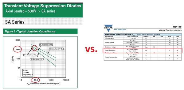
A TVS or Zener diode can have substantially more capacitance than a generic silicon diode.  From the datasheets, the 1N4148 capacitance is less than 5pF whilst the 500W TVS is over 1000pF.  And by stacking multiple 1N4148 diodes in series, the capacitance is reduced even further.

capacitance may be the issue

Attachments

Images (1)
  • capacitance may be the issue
stan2004 posted:
 
Do you have the schematic to confirm the protection device is truly across the actual 244 output pin(s)?  One issue we have seen with DCS signaling is managing capacitance - capacitance is a "known" DCS signal killer.

A TVS or Zener diode can have substantially more capacitance than a generic silicon diode.  From the datasheets, the 1N4148 capacitance is less than 5pF whilst the 500W TVS is over 1000pF.  And by stacking multiple 1N4148 diodes in series, the capacitance is reduced even further.

capacitance may be the issue

Hi Stan,

It is across the ACT244, according to what I was shown.

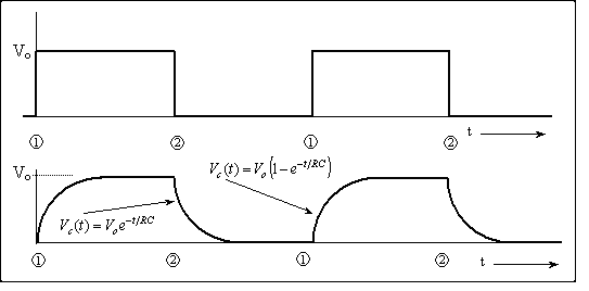
You're right on the capacitance eating the slew rate of the driver though. Lets do the math together to check GRJ's idea!

The ACT244 datasheet says the typical case device is 6.5ns TPLH and 7.0ns TPLH with a test condition 50pF external load.

So MTH gangs 4 of them together so let's assume the Thevnin equivalent of the output is 4X better than a single chnanel.. so that's lets say an average Tpd of 6.8ns /4 = 1.7ns. (I know that's an ideal case but it's okay enough for order of magnitude considerations).

Everything is RC time and scales linearly so here's some orders of magnitude:

100pF would be 3.4ns

 500pF would be 17ns Tpd time

1000pF would be 34ns Tpd time

 5000pF would be 170ns Tpd time

DCS has a rate of 3.75 MHz. Let's just call it 4 MHz so math is easy. which is 250ns Tsymbol.  Now to have a nice square wave you want TPLH+TPHL to be < 1/10 of Tsymbol ... or roughly

250ns / 10 > 2Tpd

so thats 25ns > 2 Tpd

so Tpd < 12.5ns

So calculating the specification 12.5/17 X 500pF = 367pF, so lets say 350pF.

Therefore don't pick a TVS or collection of circuits that presents more than 350pF total capacitive load to the ACT244 outputs.

Cool.

Adrian! posted:
stan2004 posted:
 
Do you have the schematic to confirm the protection device is truly across the actual 244 output pin(s)?  One issue we have seen with DCS signaling is managing capacitance - capacitance is a "known" DCS signal killer.

A TVS or Zener diode can have substantially more capacitance than a generic silicon diode.  From the datasheets, the 1N4148 capacitance is less than 5pF whilst the 500W TVS is over 1000pF.  And by stacking multiple 1N4148 diodes in series, the capacitance is reduced even further.

capacitance may be the issue

Hi Stan,

It is across the ACT244, according to what I was shown.

You're right on the capacitance eating the slew rate of the driver though. Lets do the math together to check GRJ's idea!

The ACT244 datasheet says the typical case device is 6.5ns TPLH and 7.0ns TPLH with a test condition 50pF external load.

So MTH gangs 4 of them together so let's assume the Thevnin equivalent of the output is 4X better than a single chnanel.. so that's lets say an average Tpd of 6.8ns /4 = 1.7ns. (I know that's an ideal case but it's okay enough for order of magnitude considerations).

Everything is RC time and scales linearly so here's some orders of magnitude:

100pF would be 3.4ns

 500pF would be 17ns Tpd time

1000pF would be 34ns Tpd time

 5000pF would be 170ns Tpd time

DCS has a rate of 3.75 MHz. Let's just call it 4 MHz so math is easy. which is 250ns Tsymbol.  Now to have a nice square wave you want TPLH+TPHL to be < 1/10 of Tsymbol ... or roughly

250ns / 10 > 2Tpd

so thats 25ns > 2 Tpd

so Tpd < 12.5ns

So calculating the specification 12.5/17 X 500pF = 367pF, so lets say 350pF.

Therefore don't pick a TVS or collection of circuits that presents more than 350pF total capacitive load to the ACT244 outputs.

Cool.

For those that want to know what we're talking about...

-->beyond the protection the TVS or other diode provides to the ACT244 driver, it also adds capacitance to the wire/cable.

The driver cannot deliver infinite power to the wire/cable (obviously) so it has some limit to how much current it can deliver at any moment. For design we usually model this with something called a Thevenin resistor which is a resistor in series with an ideal voltage source.

Under normal operation, as the driver switches between the ones and zeros of the data signal the ACT244 has to charge up and discharge this added capacitor through that resistor. So the time it takes to charge up and down depends on how much capacitor there is to charge, and how much series resistance there is to limit the current. We express the total delay of charging as an RC time constant. As the time constant gets longer, the time it takes go between 1 and 0 gets longer so the "square wave" data gets less square. It turns into an 1st order exponential function. So in the figure below... as the diode gets bigger and bigger and adds more and more capacitor to the wire.... the curvy part gets wider and wider as a percentage of the overall waveform width until it just doesn't work.

The equations in terms of "RC" are in there if you want them. Units are in seconds. For DCS the distance between 1 and 2 is about 250ns, so you'd want the up + down curvy part < 25ns (a tenth of the total width) so it still looks sort of squarish to the decoder.

RC_time

Sorry I'm an educator. I can't help it.

Attachments

Images (1)
  • RC_time
Last edited by Adrian!

Adrian, And a fine educator you are!!!!  Wow, that takes me back to my college days in the mid '70s.  Most of my 42-year career has been spent deploying black boxes that I don't need to remember all the electronics I learned.  I am interested in this topic, though I only have a layout room that is less than 12 feet square.  I only envision ever using one TIU, but perhaps I will need a second one someday.  I will not be running many trains at a time.  Thank you again for bringing this to our attention and describing it in an easy to understand way! 

OK, Stan has an excellent point, and it kinda' throws a monkey wrench into using either of the TVS devices we're been talking about!  Truthfully, I didn't consider the capacitance, and for low voltage parts, it's significant.  Even the 500W one at around 10V breakdown can be over 1000pf, and of course, the 3000W one is a lot more!

Junction Capacitance for Littlefuse SA5.0A 500W TVS

Junction Capacitance for Littlefuse SMDJ7.0CA 3000W TVS

It's back to the drawing board...


Attachments

Images (2)
  • mceclip0
  • mceclip1

FYI, I opened my early Rev L last night and found no TVS's installed. I think I purchased mine within a couple of months of their release. This was before folks were reporting failures. No problems so far. I couldn't find a suitable DC supply nor parts to make a high pass filter so didn't measure signal strength but will do that this weekend. If I find mine is still good I suspect I will pass on any additional protection. I am using a TMCC Lock On for a fast breaker.

Stay tuned.


Pete

Last edited by Norton

I just checked my vintage Rev L and all signals are strong. Again this one has zero TVS's like Adrian's has. 

I would suggest this "fix" by MTH has unintended consequences. Maybe some here may come up with a better mouse trap but in the meantime those with weak signals might just want to remove the TVSs and make sure you have fast breaker along with the accepted TVSs at the track connection.

Pete

Last edited by Norton

Hi Adrian !   This will be my 1st post here in a good many years, and I would NOT have known about any of the "GREAT" reading on this thread were it not for so many (mostly off YouTube) telling about all this. That said: I think this could be the genesis of some revolutionary things *(amid the little "gremlin's" we've had for all these years !).  I myself personally, have had no "real" issues UNTIL my counterpart and I decided to "try" the WiFi stuff ... and when we DID, it was the undoing of all GOOD things FOR US. 

We've ALWAYS used remotes for our Layout, and after we loaded 6.1; "the sky FELL".  Since that upgrade, we went from utter "perfection", to a system that STILL plagues us to this very moment. With several hundred engine's that once numbered almost 1,000 (in the "good ole days after we kinda "sold-off" our stuff), we regularly operated 10 engine plus consists when never under a hundred cars IN those very consists with again, near PERFECT control, and we always spank "10's". Combine this with 9 tracks, amid many multiple's on every track, and it was always a smooth-sail ... "until now"

Anyway, all our TIU's are "L's", and to this day (with 30 and some having 40 amp channel's),  I've said (for years now) that IF you want life's "acid-test" ... "I'm your man". I RUN my stuff (that's why I bought it), and until that (which I preface in the above) occurred, we WERE "Golden". While the "WiFi" worked (and very nicely), we NOW shut down what WERE great running consists, only to return to everything being literally "gone". ME ?  "I'm not very 'techey' and I myself just liked what we had, (along with 'some' tiny "gremlin's"), but all this makes MANY want ta see a light, amid revisiting this entire "ordeal" with what I have read here !. Tho we run in passive, I've watched my engine's "spark" for years while they fight to pull the long consists I demand they pull ... and again: I have NEVER had a TIU issue, "UNTIL- NOW".

Final thought:  we'd ("well me anyway"),  would just like 4.2 back, and for me "it just has ta WORK" ... BUT NOT THIS. Like Ben, Mike, and a good many others that 'push this stuff to the hilt', I will be VERY interested in whatever the "resolve" HERE turns out to be !.  After that: you get a great big WOW as your the REAL Ambassador, and a GREAT asset toward the hobby !. *(John your right there to !) ... Kudos Guy's !.  As you fan-base  G R O W S,  I'll be looking-in, amid all of the "busyness" going on here with hi-hopes and LOTS of optimism !!. 

Tho I myself am kinda on the "outs" (with trains), it STILL would be nice to occasionally re-visit an operating session or to with NO issue's.

K E E P  U P   T H E   G R E A T   W O R K  ! ! !    


Norton posted:

I just checked my vintage Rev L and all signals are strong. Again this one has zero TVS's like Adrian's has. 

I would suggest this "fix" by MTH has unintended consequences. Maybe some here may come up with a better mouse trap but in the meantime those with weak signals might just want to remove the TVSs and make sure you have fast breaker along with the accepted TVSs at the track connection.

Pete

I do have at least one of the first version L TIU. I use the Lionel 180 bricks that seem to trip for anything. I lost the smoke control on my ps3 Allegheny and they tripped. It pulled my Z1000 on my bench right down yet no tripping.

So maybe my success with my other TIUs is because of those ph180 bricks?

Here's a good start on the project.

In the schematic, both U1b and U1c are amplifying the current sense signal.  U1c, the "overload" detector, has a gain of 148, but it is slowed down by the resistor and capacitor on its output.  The time constant (RxC) is 2.6 seconds.  Multiple short hits to this RC combination would charge it up until it trips the relay latch.

U1b has a gain of 37, which means it requires 4 times as much current, but it acts instantaneously for "dead short" situations.

Lionel Powerhouse 180 Schematic

Attachments

Images (1)
  • Lionel Powerhouse 180 Schematic
RJR posted:

I agree with you, GRJ, on your evaluation of the PH180 breakers.  I wish that some talented soul would design and sell a DIY kit to assemble such breakers, to use on train layouts.  [HINT HINT]

A few already have. The Lionel TMCC Lock on is every bit as fast and unlike the 180w brick, is self restting. Also you have DCC specialties PSX-AC. Even better as the current trip point is setable up to 15 amps and it can be used in conventional mode. No need to reinvent the wheel.

Pete

Last edited by Norton

Barry, that may be true but I have installed my Lock on between the Transformer and the TIU. I use a TVS between the TIU and track. Recall its the transformer that produces the destructive spikes not the engine and the TVS should handle the rest.

I checked my nearly 8 plus year old REV L and signal is still strong so assume this protection scheme is working.

Pete

Pete, I do not use lockons or TMCC, and the PSX is too pricey.  I use breakers on many circuits, for trains and for accessories.

"Recall its the transformer that produces the destructive spikes.."  That is generally not correct.  The spikes are generated by the sparks your see---actually, when the current makes and breaks rapidly such as in a rolling derailment, the various coils on the circuit, such as loco motor windings, through inductance create voltage spikes.  No breaker on a transformer output can control these.

Barry Broskowitz posted:

Pete,

The Lionel TMCC Lock on is every bit as fast and unlike the 180w brick, is self restting. Also you have DCC specialties PSX-AC.

I'd heard (but not verified) that there were issues with signal degradation when using either one of these devices with DCS. Could you provide any insight in that regard?

Thanks!

I heard this too but I can confirm its not true.

I'm setup with the 1 PH180s + 1 PSX-ACs for each of 20 TIU channels. The DCS excursion voltage, rise time all that is identical with the TIU on the bench, and the TIU powered by these protectors. This is true in active mode, and passive mode (as long as you have a grj-choke placed in series)

Norton posted:

I just checked my vintage Rev L and all signals are strong. Again this one has zero TVS's like Adrian's has. 

I would suggest this "fix" by MTH has unintended consequences. Maybe some here may come up with a better mouse trap but in the meantime those with weak signals might just want to remove the TVSs and make sure you have fast breaker along with the accepted TVSs at the track connection.

Pete

After I saw your thoughts, I will run one like just to see actually just to see if it makes it through 7-8 hours of being beaten on.

The part I still don't know is what happened exactly that prompted the TVS diodes to be added to later Rev L boards. Someone at MTH did a lot of soldering to put those in there post-fab.

gunrunnerjohn posted:

Here's a good start on the project.

In the schematic, both U1b and U1c are amplifying the current sense signal.  U1c, the "overload" detector, has a gain of 148, but it is slowed down by the resistor and capacitor on its output.  The time constant (RxC) is 2.6 seconds.  Multiple short hits to this RC combination would charge it up until it trips the relay latch.

U1b has a gain of 37, which means it requires 4 times as much current, but it acts instantaneously for "dead short" situations.

Lionel Powerhouse 180 Schematic

It's a transient detector (LC series) instead of a current detector (R series). D4 and D3 protect the OPAs from the voltage transients. I'd guess they clamp at a much lower voltage then we're looking for though.

Andrian, beside Ben and the New Jersey Hirailers, other have replaced their REV Ls with older versions and been OK as long as fast breakers are in place. I don't have a lot of derailments but enough along with broken shorted equipment to test the TIU. My layout is also my test track and many items come to me for repair have short circuits. 

BTW when I had the cover off my TIU I noticed it has a number of 20 amp automotive fast blow fuses. I assume MTH must think their TIU should handle up to that so a 10 amp fast breaker should be more than adequate.


RJR, how much do you think someone else would have to charge to design sell at a profit another fast breaker. I suspect it would be more than 50 bucks which is what  the others sell for now.

Pete

Last edited by Norton
Norton posted:

Andrian, beside Ben and the New Jersey Hirailers, other have replaced their REV Ls with older versions and been OK as long as fast breakers are in place. I don't have a lot of derailments but enough along with broken shorted equipment to test the TIU. My layout is also my test track and many items come to me for repair have short circuits. 

BTW when I had the cover off my TIU I noticed it has a number of 20 amp automotive fast blow fuses. I assume MTH must think their TIU should handle up to that so a 10 amp fast breaker should be more than adequate.


RJR, how much do you think someone else would have to charge to design sell at a profit another fast breaker. I sispect it would be more than 50 bucks which is what  the others sell for now.

Pete

I guess it makes sense if you don't have the TVS inside the TIU it won't fail to short. That does mean the ACT244s are taking the voltage then. They have ESD clamps on-die so they aren't completely defenseless.

Do note though, we're not talking about current as the failure mechanism. The failure is caused by the Ldi/dt voltage that develops from the train motor inductance. This is what the TVS are there to clamp on.

Adrian! posted:

I guess it makes sense if you don't have the TVS inside the TIU it won't fail to short. That does mean the ACT244s are taking the voltage then. They have ESD clamps on-die so they aren't completely defenseless.


I don't have a schematic of the TIU. Exactly how are the failing TVS units connected with respect to the ACT244? Are they directly from OUT to GND?

PLCProf posted:
Adrian! posted:

I guess it makes sense if you don't have the TVS inside the TIU it won't fail to short. That does mean the ACT244s are taking the voltage then. They have ESD clamps on-die so they aren't completely defenseless.


I don't have a schematic of the TIU. Exactly how are the failing TVS units connected with respect to the ACT244? Are they directly from OUT to GND?

Yup it’s a +\- 9.2V clamp across the output.

Adrian! posted:
PLCProf posted:
Adrian! posted:

I guess it makes sense if you don't have the TVS inside the TIU it won't fail to short. That does mean the ACT244s are taking the voltage then. They have ESD clamps on-die so they aren't completely defenseless.


I don't have a schematic of the TIU. Exactly how are the failing TVS units connected with respect to the ACT244? Are they directly from OUT to GND?

Yup it’s a +\- 9.2V clamp across the output.

OK - Here is my scenario. This is pure semi-uneducated speculation.

The ACT244 spec calls for the output voltage to go above VCC or below GND by no more than 1/2 volt, probably to protect the ESD diodes from being pushed into conduction  A TVS from the output to ground will do nothing to stop negative-going transients from pulling the output below ground, not until you are way past the 1/2 volt spec, anyway.. Those diodes may well be the failure mode of the ACT244 when subject to transient voltages on its output.

I would expect that MTH was experiencing ACT244 failures and applied the TVS as a shotgun.  Apparently, the TVS is about as tender as the ACT244, but the failure effects are more noticeable. But, it doesn't really protect in all cases.

Was thinking about a couple external diodes to supplement (protect) the clamp diodes in the ACT244, then put a bigger, slower TVS (or a an appropriate zener!) from VCC to ground along with a cap (which is probably already present.) That approach would let you dissipate the transient energy somewhere other than in the signal path. It also puts the capacitance of the TVS in series with the small capacitance of a small diode, making it much less of an issue unless the diodes are conducting.

Or so it seems to me.


Interesting idea, perhaps a Schottky diode from ground and VCC to the outputs to prevent any excursion that would damage the 244 internally.  That should be low enough in capacitance to not cause the issue that the TVS may cause regarding the signal and excessive capacitance. The TVS across VCC would supply added protection, and capacitance of the TVS isn't an issue when connected across VCC.

There must be a reasonable solution that will keep the chips or the protection from self-destructing in normal operation.

If you could do a 3 component solution, we might still be able to mount it right on top of the 244.

DIODE SCHOTTKY 80V 500MA SOD123

TVS DIODE 5V 9.2V DO214AB

Last edited by gunrunnerjohn
Norton posted:
RJR posted:

I agree with you, GRJ, on your evaluation of the PH180 breakers.  I wish that some talented soul would design and sell a DIY kit to assemble such breakers, to use on train layouts.  [HINT HINT]

A few already have. The Lionel TMCC Lock on is every bit as fast and unlike the 180w brick, is self restting. Also you have DCC specialties PSX-AC. Even better as the current trip point is setable up to 15 amps and it can be used in conventional mode. No need to reinvent the wheel.

Pete

I can verify, at least in my testing, that the TMCC Direct Lockon kills the DCS signal!  I tried three of them, all of them killed the signal from my Rev. L TIU.  Perfect without the lockon, couldn't find engines with it. 

We had the same issue with the TMCC Direct Lockon at our club.  Removed them and that problem was resolved. 

There may be more than one version of the TMCC Direct Lockon, but I can assure you that at least one version of it will kill the DCS signal.

Barry Broskowitz posted:

Pete,

The Lionel TMCC Lock on is every bit as fast and unlike the 180w brick, is self restting. Also you have DCC specialties PSX-AC.

I'd heard (but not verified) that there were issues with signal degradation when using either one of these devices with DCS. Could you provide any insight in that regard?

Thanks!

I have PSX-ACs between the PH-180 bricks and my early Rev L TIU and have had no problems with DCS at all in the last 4-5 years or so. That was when I installed my current layout. Probably a lot of overkill, but it works for me. I like to feel safe and so far no problems.

I believe any problem comes from placing the PSX-ACs after the TIU. I think that is when you need to add the choke to eliminate the interference. PSX-ACs are a bit pricey, but a whole lot less than replacing circuit boards in your command control engines. Having to replace the boards in just one engine will buy you several PSCX-ACs.

Edit: After replying to this I read all the following posts after yours and saw that Adrian! said the same thing as I posted above about the PSX-AC. I will defer to his findings from now on. 

Last edited by rtr12
Adrian! posted:
PLCProf posted:
 

I don't have a schematic of the TIU. Exactly how are the failing TVS units connected with respect to the ACT244? Are they directly from OUT to GND?

Yup it’s a +\- 9.2V clamp across the output.

Are you sure about this?  I've asked this question before - about where EXACTLY the TVS is located.  In this post from a related thread, you say:

Given this case I measured the ACT244s deferentially also to make sure there wasn't something the single ended monitoring wasn't capturing.  Again in differential mode both the weak and good channels have about the same voltage swing. If you zoom into the individual bits inside both look like clean square waves.

This suggests to me that the 9.2V TVS is NOT placed across the ACT244 output.  That is, if the TVS is failing (shorting) over time, how can the good and bad channels have identical signals right at the ACT244 outputs?

In any case it seems to me that Adrian! has a solution.  1N4148 diodes are a wallet-busting 1 cent a piece!  So even with cost of the bare circuit board, we're talking about $1-2 (or so) per channel out-of-pocket cost.  Yes, there is the tedious matter of soldering diodes and such which can be a show-stopper for some guys.

1n4148 diodes for a penny a piece

It seems to me that the idea of clamping the ACT244 output pins right at the chip itself is another candidate solution.  Perhaps this solution might have fewer components and hence a smaller circuit-board and perhaps less soldering and assembly.  But I can't imagine the out-of-pocket cost being much lower than $1.  And this requires evaluation, testing, etc.    Nothing is so easy as the job you imagine someone else doing.

Attachments

Images (1)
  • 1n4148 diodes for a penny a piece

I just tossed something together with a pair of Schottky diodes to limit the output excursion above and below VCC and ground, and a 1500W TVS across the outputs.  I'm trying to see if it can be small enough to just stick to the top of the 244 and just wire it.  Obviously, I'd probably change how it connects, this is just a sizing exercise for the components right now.  These three components and the three required connections are on a board that is .675" x .2", so it's certainly small enough.  The the paralleled output pins of the 244 are connected to pin 1, and the VCC and ground are connected to pins 2 & 3.  I used a 1500W TVS, it's the size used for the TIU outputs, so it should be fairly robust.

The diodes are rated at 500ma with a peak surge of 14A, and their junction capacitance is fairly low, CT is 15pf.  The capacitance of the TVS shouldn't matter in this configuration, one of the issues we had with the other schemes.


Attachments

Images (3)
  • mceclip0
  • mceclip1
  • mceclip2
Last edited by gunrunnerjohn

From Adrian! other post,

The voltage swing looks pretty much the same in both the good and bad channels so I feel it's safe to say the ACT244s are working fine. From my understanding of the traces on the PCB it looks like they the 4 left channels together to form a positive output and the 4 right channels together to form a negative output, then use it differential to drive the output transformer after a filtering network.

In other words of the 8 outputs per ACT244 chip, 4 are tied together to form "output+" and other 4 are tied together to form "output-."  Hence two clamps per ACT244.  I'd think you'd want to put both clamps on one board with 4 connections to the ACT244:  VCC, GND, output+, output-.  Just a suggestion.

gunrunnerjohn posted:

I was curious if Adrian or Stan were going to weigh in and give me their thoughts on this approach.  Until I get a layout built, I can't really do any serious testing either.  I suspect also, I won't have the issues that a large club layout would have with the TIU's.

I like what you drew up. I don't see any reason it wouldn't work (testing is always best of course). 

Any thoughts on a simple signal level monitor as oppose to a costy oscilloscope? I've got 2 or 3 ideas but they're all mixed-signal/digital ways so far (which are still expensive)


I wanted to see if anyone had any issues with what's there before trying to make a couple.  I think it would be a lot easier to use than the zillions of diodes you originally used, the question is how effective would it be in protecting the TIU 244's.  That can only be determined by testing in an environment that destroys TIU's.  Wait... You have such an environment!

If I share this project on OSH Park, would you be interested in putting a couple together and seeing if they survive your club torture tests?  A preview shows that the board cost is 80 cents for three of them, shipped free.   Of course, you do need a couple bucks worth of components.

The smallest dimension they'll do is .25", so I had to enlarge it slightly.

Here's the OSH Park Link to the shared design: MTH TIU Signal Protection

Attachments

Images (2)
  • mceclip0
  • mceclip0
Last edited by gunrunnerjohn

What makes me nervous about the proposed alternative is that the original 1N4148 method was apparently developed in coordination with MTH themselves (?).  As I've suggested earlier, I don't believe the MTH clamp is directly on the ACT244 output based on tests Adrian! made months ago.  What's my point?  While it's been stated that the clamp protects the ACT244, does anyone know with certainty that the clamp doesn't protect OTHER components too?  When Adrian! made the oscilloscope tests in the other post, I recall there were other semiconductor components AFTER the ACT244 in the filter circuit.

But if someone is willing to do the assembly and testing of the direct-on-the-ACT244 method then by all means fire up the soldering iron!  I'd also think that one would always want to install clamps on all 4 channels so perhaps the circuit board should have 4 clamps which might save wiring (since VCC and GND) could be shared.

Even if remaining with the 1N4148 approach, I'm pretty certain you could cut the PCB board size in half using tighter bends on the leads and it looks to me like the hole sizes are larger than they need be.  You could probably use the SMD LL4148 leadless version which would save space and assembly time and those are also a penny a piece.  And as above I'd think you'd want to put 4 clamps on one board.


stan2004 posted:

What makes me nervous about the proposed alternative is that the original 1N4148 method was apparently developed in coordination with MTH themselves (?).  As I've suggested earlier, I don't believe the MTH clamp is directly on the ACT244 output based on tests Adrian! made months ago.  What's my point?  While it's been stated that the clamp protects the ACT244, does anyone know with certainty that the clamp doesn't protect OTHER components too?  When Adrian! made the oscilloscope tests in the other post, I recall there were other semiconductor components AFTER the ACT244 in the filter circuit.

But if someone is willing to do the assembly and testing of the direct-on-the-ACT244 method then by all means fire up the soldering iron!  I'd also think that one would always want to install clamps on all 4 channels so perhaps the circuit board should have 4 clamps which might save wiring (since VCC and GND) could be shared.

Even if remaining with the 1N4148 approach, I'm pretty certain you could cut the PCB board size in half using tighter bends on the leads and it looks to me like the hole sizes are larger than they need be.  You could probably use the SMD LL4148 leadless version which would save space and assembly time and those are also a penny a piece.  And as above I'd think you'd want to put 4 clamps on one board.


Yeah there's some discrete FETs in the output network. I haven't seen them fail, even when the diodes are short (although.... maybe that's *because* the TVS diodes are short and sacrificially protecting them ). I don't have the full network schematic, just a lot of slow (yes or no) question sessions. If anyone is willing to put time into a test PCB, I'm willing to install it in a TIU and test it in our battle arena.

My prototype wasn't meant for any kind of production or minimum cost answer, it was me coming up with a quick solution and testing it empirically over and over to make sure its functional. The idea of posting the details was to start a discussion (check that off) and to get the clever folks like GRJ to refine it.

Also just to throw this out there based on some of the comments above. I don't want to give anyone the wrong idea... not *every* DCS problem you have is because the TVS diodes failed in your TIU. If you're rough on trains, and have a later Rev L TIU, you may have this problem too, but outside of that, lots of other things can also go wrong!

Adrian, Granted other issues arise, but blowing 1-2 channels on a TIU adds up for our club, we are running 5 on the layout and have 15 we rotate as send off for repairs, if this fixes the blown channels, we are one step ahead in making the layout less maintenance intensive and our crew can make new additions vice only keeping the old running. 

Shorts from derailments are a daily problem, not all members are lucky with their trains , whether inattention or a switch being thrown by someone not watching , a bad coupler opening and train meets the tail end or doesn't like a turnout. It is impossible to foolproof a layout, but removing one problem sure feels good.

Adrian! posted:

Any thoughts on a simple signal level monitor as oppose to a costy oscilloscope? I've got 2 or 3 ideas but they're all mixed-signal/digital ways so far (which are still expensive)

As you pointed out earlier, it can be challenge to design a low-cost DCS signal level meter given the short, high-frequency bursts.  To that end I'd think you could put a suspect DCS-channel into the Proto-cast mode where it sends hundreds or thousands of times more DCS packets than normal DCS use.  My thinking is this might make it as simple as a high-pass filter (to reject the 60 Hz), and a simple averaging diode detector which could feed any DC voltmeter.  Yes, this would not provide "in-service" monitoring in that you would have to stop playing with trains and put on a diagnostic-mode hat.

There was a similar widget made for TMCC level monitoring.  That is, a signal level pin was tapped on the 455 kHz demodulator chip which then fed a DC voltmeter.  As I recall, you just added a couple components to make it work.  This worked because the 455 kHz signal is always present.  Hence this is why I think some way to get the DCS signal to be on all the time or at least much more frequent would make it easier to measure.

I have repaired my fair share of TIU over the past few years.  I do communicate with MTH Senior Tech who does the majority of repairs at MTH.  So here are some points.

TIUs repairs are a small fraction of the repair work compared to engine repairs and upgrades.

After a TIU repair they don't come back for re-repair.  I did have one comeback, which I attribute to a faulty component or too much heat when reinstalling (VAR Channel FET)

I have not seen many Rev L with the modified TVS added, though I will pay more attention to this.

Pre Rev L, the Transmit failure was possible, but more likely the Receiver chip took a hit, especially if all channels effected.

A hard hit on one channel transmit chip can cause sufficient of a load on the 5V regulator, that negatively effects all other channels since their input voltage has dropped too low.  This is why it is very nice to know what channel was being used when the failure occurred. Otherwise I start removing transmit chips until I find the culprit.

Post Rev L, the receiver chip rarely takes a hit anymore.

You can have a loss of DCS capability, but the TIU transmits fine, but it is receiving the return signal at issue.  This can effect half the channels or all of them.  Again this is rare.

The only components I have seen damaged are the main power TVS, VAR FET (usually just one of the 4), ACT Transmitter, Receiver Chip, Memory (Rare and usually the very early units), a damaged Aux power jack, fuses and melted terminal housings, and the power inductors over heated and melting changing inductance.

I have only had 2 TIU that I can remember that I could not fix.  Early Rev G with a burned up main trace and memory damage, and Later REV L.  MTH would acknowledge that occasionally some other unknown component may be damaged that kills a TIU making it not worthy of repair, but this is very, very rare.

My point, For REV L with added TVS for transmit protection, I think Adrien or GRJ device would be acceptable if test shows it holds up better.  I don't think it is protecting any other components.  Remember this is an add on mod designed to better protect ACT244.

I think the normal home owner and small club environments probably do not see anything like this; though I am sure there are occasional failures.

For those that have failures but keep using the TIU it might make sense your loosing other channels because you have not addressed the faulty component which is still on the buss being powered by the 5V source despite no input power to that channel. 

I have repaired ACT244 on Rev L with TVS mod and the DCS came right back, I never tested if the TVS was shorted.  I will add this to my procedure, but it is an additional factor, that not all TVS short prior to an ACT244 going bad.  G


I have put the ACT244 in three TIU's now, and as I don't see nearly as many TIU's for repair as George, I thought that was a lot of failures.  I think I've only had a handful of the TVS diodes on the output fail on the TIU's, so the ACT244 failure is almost as common in my limited sample size.

I'm going to check our club TIU's for signal strength, some of the issues we have with DCS could easily be explained by lower DCS signal amplitude, maybe we have some partial failures that we don't know about.

stan2004 posted:

What makes me nervous about the proposed alternative is that the original 1N4148 method was apparently developed in coordination with MTH themselves (?).  As I've suggested earlier, I don't believe the MTH clamp is directly on the ACT244 output based on tests Adrian! made months ago.  What's my point?  While it's been stated that the clamp protects the ACT244, does anyone know with certainty that the clamp doesn't protect OTHER components too?  When Adrian! made the oscilloscope tests in the other post, I recall there were other semiconductor components AFTER the ACT244 in the filter circuit.

The diode method obviously does work, I think the object of the exercise is to try to do similar protection with fewer components.  The only real way to know if the alternative I proposed will work is for some extended testing in a "real world" environment where we know the failures are happening.

stan2004 posted:

But if someone is willing to do the assembly and testing of the direct-on-the-ACT244 method then by all means fire up the soldering iron!  I'd also think that one would always want to install clamps on all 4 channels so perhaps the circuit board should have 4 clamps which might save wiring (since VCC and GND) could be shared.

I'm somewhat confused about the four clamps, I thought four outputs were paralleled for each side of the signal.  That being the case, why isn't the circuit below sufficient to protect against excursions above and below VCC and ground for both groups of outputs?  This should handle one of the ACT244 chips.  As for one board servicing all the channels, I thought one of the desires was to keep the wiring short.  I wanted this unit to sit on top of the ACT244, one for each channel.  To that end, it's only 1/4" wide and .65" long.

Attachments

Images (2)
  • mceclip0
  • mceclip1
Last edited by gunrunnerjohn
gunrunnerjohn posted:

...

stan2004 posted:

But if someone is willing to do the assembly and testing of the direct-on-the-ACT244 method then by all means fire up the soldering iron!  I'd also think that one would always want to install clamps on all 4 channels so perhaps the circuit board should have 4 clamps which might save wiring (since VCC and GND) could be shared.

I'm somewhat confused about the four clamps, I thought four outputs were paralleled for each side of the signal.  That being the case, why isn't the circuit below sufficient to protect against excursions above and below VCC and ground for both groups of outputs?  This should handle one of the ACT244 chips.  As for one board servicing all the channels, I thought one of the desires was to keep the wiring short.  I wanted this unit to sit on top of the ACT244, one for each channel.  To that end, it's only 1/4" wide and .65" long.

By all clamps on all 4 channels, I mean all 4 TIU channels (Fix1,Fix2,Var1,Var2).  So the board could share VCC and GND between all 4 channels and save 6 connections to the TIU board.  As for short wire lengths, I was keying off the earlier photo which showed fairly long wires.

beef

I figure the boards were placed where they are because there are no tall components in that area.  But as your clamp is placed at a different point in the circuit, perhaps wire length is factor.  In which case 4 individual boards would make sense to allow placement directly above the 4 individual ACT244 chips.

I assume your E1..E4 pads line up right above the corresponding pins on a SO-20Wide package allowing placement right on the chip? In which case would it make sense to rotate the E1..E4 pads 90 degrees so only a single right-angle wire bend between board pad and chip pin.

Attachments

Images (1)
  • beef

I thought about the orientation of the pads, but due to the small size of the board and pads, I wanted a bit more "meat" soldered to the pad.  I hesitate to make the pads smaller as they lose strength in the bond to the PCB material, makes them too easy to pull off.  I deliberately made this a one-sided board so there were no traces on the bottom and I could stick it right on the ACT244.  One thing I didn't check is the orientation of the ACT244 to see if I had to allow the overhang to be in a different place, or even perhaps have two versions, kinda' left-handed and right-handed to fit on all the chips without hitting anything close.  I'll have to "pop the top" of a TIU to check those clearances.

As for the longer wires, I figured any extra propagation delays I introduced with the longer wires would add to the response time of the diodes, so I thought the shorter and more compact edition would work out best.  It remains to be seen if this is an effective solution to the issue, but I figured I'd give it the best chance to succeed.  Also, his TVS was right at the chip, and now that we're going to likely slower diodes, I didn't want to introduce any extra delay.

By rotating pads I don't see why they would get smaller.  I mean like shown in orange:

mceclip1

Would probably mean moving some components around but since you have 4 pins on each side to choose from for the out+ and out-, perhaps not a big deal to slide the middle components around.  Also, I would think one way of assembling and installing would be to use solid 24 or 26 AWG (or clipped resistor leads).  They would be soldered as shown in red.  Then bent down 90 degrees.  The board would then be dropped over the ACT244.  Then 4 solder joints to the ACT244 pins.  I'm sure there are many ways to do this but clearly it's the final attachment step to the ACT244 that will be the hardest part.

Also, maybe also change the white silkscreen from E1...E4 to the actual ACT244 pin numbers such as 10 for GND, 20 for VCC, etc.

Attachments

Images (1)
  • mceclip1

It would be easy to move the components, I can do that.  I didn't know the pins for the two groups of outputs for sure, are they common on one side of the chip and then common on the other side?  If so, I could put the pin number on them, and also locate them directly above the pin in question on the 244 chip.

From this picture, I think I need to have the excess hang-over of the board on the other end, the back of one of the 244's butts up against a large capacitor, the one on the extreme left here.  Without opening up one here, I think the four ACT244 chips are the ones indicated, pretty sure that's what I've indicated.

TIU PCB

Attachments

Images (1)
  • TIU PCB

I figure this is yet another chore to verify that relevant revisions of the TIU board group the four left and four right outputs together as suggested here for all 4 channels.  Given the ACT244 pinout, it's hard to imagine why you wouldn't group all the lefts together and all the rights together no matter the revision but who knows!

ACT244

For extra credit, one might research if other DCS devices (DCS Commander, Remote Commander, Explorer, etc.) also use the same ACT244 scheme and hence be candidates for this protection.

I see what you mean about the clearance on the leftmost ACT244. 

I suppose the neat thing about your single-sided surface-mount design is you could, for no extra cost, put one style on one side of the board and a different style on the other side of the board!


Attachments

Images (1)
  • ACT244
stan2004 posted:

I figure this is yet another chore to verify that relevant revisions of the TIU board group the four left and four right outputs together as suggested here for all 4 channels.  Given the ACT244 pinout, it's hard to imagine why you wouldn't group all the lefts together and all the rights together no matter the revision but who knows!

That's what I thought, and I made that "assumption".  However, I suspect I should verify it before going to press.

stan2004 posted:

For extra credit, one might research if other DCS devices (DCS Commander, Remote Commander, Explorer, etc.) also use the same ACT244 scheme and hence be candidates for this protection.

Interesting point about the other devices.  I don't have a DCS-RC handy to check, the only part I see in a fuzzy photo I have is U3, and it looks to be a different pitch part than the TIU.  I don't have the Remote Commander or DCS Explorer, so no possibility of checking those.

stan2004 posted:
I see what you mean about the clearance on the leftmost ACT244. 


I suppose the neat thing about your single-sided surface-mount design is you could, for no extra cost, put one style on one side of the board and a different style on the other side of the board!

I don't see an easy way to convince the PCB layout package to do the trick with two circuits.  In any case, since I'd need boards of both designs, I don't see having two different boards as a big deal, they're very cheap.  I can't really build both circuits on one board, I can only use one anyway.

Here's a new layout.  I had to do double-sided to compress it, but I only need one design now.  It's .3" x .52" in size, and it'll perch on any of the 20 pin SOIC packages for the ACT244, no overhang.  The pads are labeled with pin numbers, and they're spaced correctly to line up with the corresponding pin on the ACT244.  If this works for the needed protection, it would be a compact solution to the issue.

Attachments

Images (1)
  • mceclip0

I think you've gone as far as you ought to go until someone steps up to assemble and evaluate. 

With either design alternative, I'm curious to see how the costs work out.  I figure the component/board costs are negligible compared to labor and cost for 2-way shipping of a TIU.  I suspect most guys would want someone else to install these.

As far as evaluating a beta board, we can do that if someone shows the process for us that are technically challenged. We have a scope but only one member knows how to use it and I hesitate to volunteer him with his current load of keeping the wiring functioning in the layout.

Yep, the cost for components and the board should be pretty small.  It would be nice for someone with a TIU handy to verify that Pin-17 and Pin-8 are on the two grouped outputs.  I am assuming they are since they're on opposite sides, but you never know.

Here's a Link to the latest shared version of the board.  MTH TIU Signal Protection PCB at OSH Park

These are the diodes used, quantities in ().

(1) DIODE SCHOTTKY 80V 500MA SOD123

(4) TVS DIODE 5V 9.2V DO214AB

The cost of the parts and the board is less than $3 for a board in small quantities, the board is still 80 cents for three of them, the five diodes are less than $2.  I order most boards like this with 2oz copper and .8mm thickness.  I get lower impedance traces and thinner boards.

Last edited by gunrunnerjohn
gunrunnerjohn posted:

It would be nice for someone with a TIU handy to verify that Pin-17 and Pin-8 are on the two grouped outputs.  I am assuming they are since they're on opposite sides, but you never know.

Not sure what you mean.  Your board diagram correctly shows P7 and P18 as being outputs.  The close up TIU photos of the mounted ACT244 show the drivers are connected as 4 left inputs driving right 4 right outputs (12,14,16,18),  and 4 right inputs driving 4 left outputs (3,5,7,9). 

ACT244 outputs

Attachments

Images (1)
  • ACT244 outputs

I have an early REV. L TIU that FIXED 1 sends no watch dog signal and cannot communicate with the engine after it's started. All other channels work fine in command mode. Would this be a fried ACT244 on my FIXED 1 channel? I opened it up and don't see any TVS's on the ACT244's unless their soldered on the bottom side of the board. Also, if the problem is a bad ACT244, is it possible to replace it with a socket, to make it easier to replace if it ever fails again?

stan2004 posted:
gunrunnerjohn posted:

It would be nice for someone with a TIU handy to verify that Pin-17 and Pin-8 are on the two grouped outputs.  I am assuming they are since they're on opposite sides, but you never know.

Not sure what you mean.  Your board diagram correctly shows P7 and P18 as being outputs.  The close up TIU photos of the mounted ACT244 show the drivers are connected as 4 left inputs driving right 4 right outputs (12,14,16,18),  and 4 right inputs driving 4 left outputs (3,5,7,9). 

ACT244 outputs

Stan, I was asking if the TIU was actually wired with the groups you indicate.  I know where I put the pins, but I didn't have a TIU on the bench to see if that's how they were grouped.

Ron_S posted:

John,

I ordered 9 boards and enough of the diodes and TVS to populate the 9 boards. I will work on soldering them into units and do a test run on a wounded TIU to see if it works. 

 If the TIU is already wounded, you may have to replace the 74ACT244 as well.  This won't fix cooked outputs, it's only protecting them, or at least the hope is it will protect them.

Dave Zucal posted:

I have an early REV. L TIU that FIXED 1 sends no watch dog signal and cannot communicate with the engine after it's started. All other channels work fine in command mode. Would this be a fried ACT244 on my FIXED 1 channel? I opened it up and don't see any TVS's on the ACT244's unless their soldered on the bottom side of the board. Also, if the problem is a bad ACT244, is it possible to replace it with a socket, to make it easier to replace if it ever fails again?

The 74ACT244 is a likely suspect, but it's not really possible to use a socket as it's a SOIC surface mount part.  If you look at the first post of this thread, Adrian shows you were they soldered the TVS parts to "protect" the 74ACT244 chips, three were on the top, one was on the bottom.  FWIW, with that symptom, that's the first part I go for, I haven't seen the other associated parts fail yet.

gunrunnerjohn posted:

Stan, I was asking if the TIU was actually wired with the groups you indicate.  I know where I put the pins, but I didn't have a TIU on the bench to see if that's how they were grouped.

OK - I see what you mean. So whoever is stepping up to try your method should take a few seconds to confirm the circuit traces around the TIU look as indicated in the close up photos of the ACT244 chips I posted earlier.  The idea there was to show that all 4 ACT244 chips have circuit traces connecting 4 left pins and circuit traces connecting 4 right pins.  The red lines show the connections being made by the traces.  As it turns out, some of the chips in this particular board are connecting 4 inputs and some are connecting 4 outputs.  This doesn't matter so seeing this type of trace pattern is good enough to confirm the desired left right groupings of 4.

ACT244 4 by 4

Attachments

Images (1)
  • ACT244 4 by 4

OOPS!

My previous board layout had an error!  I slipped a digit and specified the footprint of the TVS as a DO-214AC, however it actually has a footprint of a DO-214AB.  This doesn't sound like much, but it's actually HUGE!  That being the case, my previous layout didn't really work as the TVS is much larger than I allowed for. 

How much larger you might ask...

Footprint

The answer, as you can see above, is GOBS! 

So, back to the drawing board, I think I have a reasonable solution.  Since the desire was to keep the board the size of the ACT244 to avoid any issues with clearances, I decided to put the large TVS on the bottom and the four diodes on the top.


This will make the stack slightly taller, but that doesn't seem to present an issue from what I see.  It still remains in the footprint of the ACT244.  I will have to update my project files on OSH Park to reflect the new layout.

Sorry for any inconvenience, I'm about to receive some boards that I'll be tossing and starting over, as I suspect a couple other people are.

This is a link to the new layout: MTH TIU Signal Protection PCB

Attachments

Images (3)
  • Footprint
  • mceclip0
  • mceclip1
Last edited by gunrunnerjohn

With Adrian's extensive help (Thanks again, Adrian), we've landed on the beefier TVS as shown in his original post of the back of the TIU with the four yellow sketched diodes. His daughter card design is probably the "silver bullet" fix but isn't exactly practical in a production sense. That's why we are going with the four larger TVS's attached to the signal transformer on the back of the TIU PCB. 

All new Rev L TIU's produced going forward will contain these TVS's. In the field we have a Service Bulletin that was released today, in fact, that outlines removing the old mod (wimpy diodes) with the larger ones. While Adrian noted that there were still occasional failures, it's a balance of fixing it without re-designing and laying out a new PCB vs. applying a solution that gets most TIU's serviceable long-term. 

From MTH's Service perspective, we will be adding this mod to all TIU's that arrive in for service with blown xmit chips or any condition that would indicate such. Additionally, this mod can be applied to any Rev TIU you have in your inventory. The vast majority of TIU's we've seen come through Service as well reports from the field have been on Rev L TIU's. Only the Rev L TIU's have the old mod applied. 

For those of you who are ASC's you will have this service bulletin. I've also shared it with Barry Broskowitz so he can post it on this forum to let those that have the ability apply it to their TIU's. MTH isn't carrying the component at this time so you can get it from Digi-Key per the bulletin.

NOTE - If you are NOT an ASC and you attempt this mod and damage a TIU that is under warranty, it will void the warranty. 

Thanks,

MTH 

MTH posted:

With Adrian's extensive help (Thanks again, Adrian), we've landed on the beefier TVS as shown in his original post of the back of the TIU with the four yellow sketched diodes. His daughter card design is probably the "silver bullet" fix but isn't exactly practical in a production sense. That's why we are going with the four larger TVS's attached to the signal transformer on the back of the TIU PCB. 

All new Rev L TIU's produced going forward will contain these TVS's. In the field we have a Service Bulletin that was released today, in fact, that outlines removing the old mod (wimpy diodes) with the larger ones. While Adrian noted that there were still occasional failures, it's a balance of fixing it without re-designing and laying out a new PCB vs. applying a solution that gets most TIU's serviceable long-term. 

From MTH's Service perspective, we will be adding this mod to all TIU's that arrive in for service with blown xmit chips or any condition that would indicate such. Additionally, this mod can be applied to any Rev TIU you have in your inventory. The vast majority of TIU's we've seen come through Service as well reports from the field have been on Rev L TIU's. Only the Rev L TIU's have the old mod applied. 

For those of you who are ASC's you will have this service bulletin. I've also shared it with Barry Broskowitz so he can post it on this forum to let those that have the ability apply it to their TIU's. MTH isn't carrying the component at this time so you can get it from Digi-Key per the bulletin.

NOTE - If you are NOT an ASC and you attempt this mod and damage a TIU that is under warranty, it will void the warranty. 

Thanks,

MTH 

Very glad to help any way I can!  It makes me happy to think of all the layouts that will benefit from this study!

MTH posted:

With Adrian's extensive help (Thanks again, Adrian), we've landed on the beefier TVS as shown in his original post of the back of the TIU with the four yellow sketched diodes. His daughter card design is probably the "silver bullet" fix but isn't exactly practical in a production sense. That's why we are going with the four larger TVS's attached to the signal transformer on the back of the TIU PCB. 

If I understand this MTH statement, and combining with earlier discussion, the daughter-card approach using a handful of 1-cent diodes is the superior technical solution.  It eliminates the problem period, end-of-story.  OTOH, the single TVS method might fail over time particularly in rough operating environments...but doing-the-numbers makes this a better business solution.  I get that.

That said, and this is just my opinion, if you are going to make the mod yourself...or have someone do it for you, I'd find someone willing/able to install the daughter card mod (or GRJ's proposed alternative if that proves out).  The difference in component cost is negligible.  I'd think labor/shipping/overhead of making the mod is something you'd only want to do once.

"From MTH's Service perspective, we will be adding this mod to all TIU's that arrive in for service with blown xmit chips or any condition that would indicate such. Additionally, this mod can be applied to any Rev TIU you have in your inventory."

So I'm clear, MTH, this new device would benefit Rev G, H, & I TIUs by adding protection.  Yet my ancient Rev G's, which have suffered through many derailments, don't seem to have lost signal strength.  What would you do with pre-Rev Ls that work fine and have been rock solid (at least since MTH repaired the Rev G's some 10-15 years ago).

Thanks, GRJ.  You do make sense.  But, given history, it should be done on a Rev L.  I have a Rev L to practice on, because it has failed so many times and been in the shop so many times I've given up on it--latest is that it won't control or even cut track voltage, and I won't stuff it with any more $$.

Barry Broskowitz posted:

Apparently Adrian's club did run in passive mode and still managed to cook TIU's.

I find myself scratching my head over this statement. My understanding is that a short circuit won't affect a TIU in Passive Mode. Is this not true for a current spike, as well?

It's not current that does the damage. It's the di/dt voltage. (here's a tutorial). The train is a motor (inductive). When the current jumps from the short, the 1st derivative, scaled by the inductance is developed across the rails.

An ideal short is a scaled step function Ks I(t)

where I(t) = 0 on the interval t<0,   I(t)=1 on the interval (t>0) and Ks is a scale for the current:

So the first derivative is the dirac (delta) function centered at t=0;

V(t) = d KsU(t)/dt

V(t) = Ks dirac(t)

The weight of the delta function voltage is Ks which is the peak voltage the TIU driver experiences. This is what the TVS is there to clamp.


Adrian! posted:
Barry Broskowitz posted:

Apparently Adrian's club did run in passive mode and still managed to cook TIU's.

I find myself scratching my head over this statement. My understanding is that a short circuit won't affect a TIU in Passive Mode. Is this not true for a current spike, as well?

It's not current that does the damage. It's the di/dt voltage. (here's a tutorial). The train is a motor (inductive). When the current jumps from the short, the 1st derivative, scaled by the inductance is developed across the rails.

An ideal short is a scaled step function Ks I(t)

where I(t) = 0 on the interval t<0,   I(t)=1 on the interval (t>0) and Ks is a scale for the current:

So the first derivative is the dirac (delta) function centered at t=0;

V(t) = d KsU(t)/dt

V(t) = Ks dirac(t)

The weight of the delta function voltage is Ks which is the peak voltage the TIU driver experiences. This is what the TVS is there to clamp.


I was following this thread until now.

Screenshot_2018-05-23-13-03-39-1

Attachments

Images (1)
  • Screenshot_2018-05-23-13-03-39-1
Barry Broskowitz posted:

Apparently Adrian's club did run in passive mode and still managed to cook TIU's.

I find myself scratching my head over this statement. My understanding is that a short circuit won't affect a TIU in Passive Mode. Is this not true for a current spike, as well?

I see Adrian beat me to it, but yes, a voltage spoke will affect any electronics that's exposed to it, it doesn't matter if there is current flowing in that circuit, it just has to be connected.  One statement in his tutorial says it all.

Opening of inductive circuit may cause voltage spikes of thousands of volts!

Think of how the Kettering ignition system system that we have used for a hundred years in cars works, from a lowly 12V battery, we manage to generate thousands of volts to fire the plug.  It's all about the collapsing field in the inductor.

Last edited by gunrunnerjohn

Hey Barry sounds like another chapter, if not another book . Adrian even has awoken the sleeping Giant...Lol!

Great bunch of info guys, and I know it is answering questions, that all we've ever done in the past is use the volt/amp meter, and the Signal strength meter, when hunting for signal problems or lack there of.....Thanks to all of you folks on here again.....

The di/dt voltage spike from the motor inductance in O-gauge engines is usually behind the bridge-rectifier and DC bus  capacitance and hence does NOT reach the track.  Instead, it is the inductance of the track itself and the track-to-transformer wiring that "generates" the killer voltage spikes.  

Above video shows my "surge detector" that can be moved around a layout to localize the severity/frequency of voltage spikes.   The 2 red LEDs flash when there is a positive or negative voltage spike on the track.  This widget was discussed in an earlier thread about spikes, TVS placement, etc.   Nothing to do with whether the TIU is in passive or active mode.  Obviously there is no motor inductance in this setup.  Instead the voltage spikes (flashing red pulses) are caused by the rapid current changes from shorting the track which might be from a derailment, going over a switch/turnout, whatever.


Last edited by stan2004
stan2004 posted:

The di/dt voltage spike from the motor inductance in O-gauge engines is usually behind the bridge-rectifier and DC bus  capacitance and hence does NOT reach the track.  Instead, it is the inductance of the track itself and the track-to-transformer wiring that "generates" the killer voltage spikes.  

Above video shows my "surge detector" that can be moved around a layout to localize the severity/frequency of voltage spikes.   The 2 red LEDs flash when there is a positive or negative voltage spike on the track.  This widget was discussed in an earlier thread about spikes, TVS placement, etc.   Nothing to do with whether the TIU is in passive or active mode.  Obviously there is no motor inductance in this setup.  Instead the voltage spikes (flashing red pulses) are caused by the rapid current changes from shorting the track which might be from a derailment, going over a switch/turnout, whatever.


Yeah the cabling/track inductance makes more sense than the motor inductance after spending 20 seconds thinking about the circuit conditions during a short.

Also...  You know those chokes all of us are putting in series with the power supplies to keep the RF impedance high? Under a short circuit transient those are going to cause a massive di/dt event at the TIU too...


1. It's inline with the full short circuit current pulse

2. compared to a 1KV transient... either side of the transformer is like a solid ground. The impedance is low looking into it (which is why the choke was there in the first place), and on the KV scale (ground) or (ground + 18V) are the same thing.

3. So the transformer side of the choke is basically pegged to low potential, and the choke has a KV across it, meaning the TIU/track will have a KV across it.

 Maybe I'll be putting a TVS in parallel with those too in the future.

stan2004 posted:

The di/dt voltage spike from the motor inductance in O-gauge engines is usually behind the bridge-rectifier and DC bus  capacitance and hence does NOT reach the track.  Instead, it is the inductance of the track itself and the track-to-transformer wiring that "generates" the killer voltage spikes.  

Above video shows my "surge detector" that can be moved around a layout to localize the severity/frequency of voltage spikes.   The 2 red LEDs flash when there is a positive or negative voltage spike on the track.  This widget was discussed in an earlier thread about spikes, TVS placement, etc.   Nothing to do with whether the TIU is in passive or active mode.  Obviously there is no motor inductance in this setup.  Instead the voltage spikes (flashing red pulses) are caused by the rapid current changes from shorting the track which might be from a derailment, going over a switch/turnout, whatever.


I don't know why I found this so entertaining? but I did. Although it seems crazy to do this it does represent what can happen during a derailment.

You must be using MTH power supplies though? The (big L's) PH180s breaker trips if the weather changes ........or if you stare at the track too hard...… get it?

I think of the people designing things and always wonder what they think is abusive? I watched our 2 grandsons play tug of war with a brand new MTH RTR steamer and tender that I bought them. They were yelling it's my turn to run it!

 …..and I come here and read of users complaining that the wireless tether breaks too easily.

Adrian! posted:
 
Also...  You know those chokes all of us are putting in series with the power supplies to keep the RF impedance high? Under a short circuit transient those are going to cause a massive di/dt event at the TIU too...
 

Good point.  If you open the TIU you will see such a choke at the Voltage In connectors.  A short circuit current on a TIU output channel flows thru the TIU choke.  So the di/dt phenomenon, for lack of a better term, is the same as the passive-mode TIU when adding the choke between the PSX-AC and the track.  Same choke application - to keep the RF impedance high to protect the DCS-signal integrity.

Engineer-Joe posted:
...

You must be using MTH power supplies though? The (big L's) PH180s breaker trips if the weather changes ...

As I see it, the breaker/fuse method is a completely separate issue.  It doesn't matter how fast or type of power supply interruption method is used.  Here's my thinking.  A short-circuit consists of a rapid increase in current when the short starts - this is one di/dt event.  At some point, the breaker responds to the overcurrent and then interrupts the current causing a rapid decrease in current - this is another di/dt event.

Perhaps it was explained in one of the various threads, but it still baffles me as to what's so special about Adrian's club layout that causes the TIU signal level failures with clock-like repeatability.  Do they really have that many more short-circuit derailments per day that any other layout?  Or maybe no one has undertaken the (considerable) time/effort to gather data.

Another source of di/dt induced spikes is momentary losses of track power going over a section of dirty track of whatever.  That is, several Amps of current flows from track thru the wheels/rollers to the moving engine.  Dirty track, rollers, whatever cause brief losses of contact which causes track current to drop to zero (a di/dt event) and then instantly jump back up to whatever current (another di/dt event).  The size of the current change may be less than that of a short-circuit (10 Amps or whatever) but then these micro-interruptions are surely occurring more frequently than derailments.  So is this a case of death-by-a-thousand-cuts?  


Theory versus practice, you guys are going to start scaring people.  Adrian did post an event sheet somewhere, maybe a different post.  Yes it was insane, almost  two or more derailments a minute, some time simultaneously.  If we step back, no one else was reporting this kind of problem other then large clubs.  TIUs do have failures so this is occurring, but folks plug stuff in the wrong holes, have major events, or just loose one channel out of 4 even thought they are using 4 channels.  I said this earlier, I have not seen this kind of issue, and there has only been a few, maybe 2 TIU I could not repair, and I have NEVER Replaced a TVS on a Mod Rev L.  NO other TIU have these TVS.  Having said that, maybe one of the two not repaired had a bad TVS.  So the average home is not having this problem.

So to start talking about all these di/dt events from dirty track, dirty wheels, bad pickup rollers is going to drive people scared.  Based on your theory I should be repairing TIU at the same rate as engines, and that is not even close.  Maybe .5% of my work is TIU, if that; and other techs send people to me.  Why don't we see how MTH fix works, plus I am sure some (Clubs and others) will buy Johns fix.   G

GGG posted:

Theory versus practice, you guys are going to start scaring people.

I got rid of all my older TIUs and now have only Rev L versions (two primary and one backup).  Following this topic got me wondering if I should sell my Rev Ls and go back to older ones.  Now G has me wondering if I should keep my Rev Ls and hope for the best (he did state an unfixable TIU may of had this problem).

Here is my power setup for each TIU channel:

Power setup for each channel

I'm using more power but have a much faster CB (PSX) and a large choke (34A 22uH).  For you experts that know what you are talking about, is this setup more or less susceptible to the failure you are talking about.  If it is more susceptible I may get rid of the Rev Ls.

Attachments

Images (1)
  • Power setup for each channel
GGG posted:

Theory versus practice, you guys are going to start scaring people.  Adrian did post an event sheet somewhere, maybe a different post.  Yes it was insane, almost  two or more derailments a minute, some time simultaneously.  If we step back, no one else was reporting this kind of problem other then large clubs.  TIUs do have failures so this is occurring, but folks plug stuff in the wrong holes, have major events, or just loose one channel out of 4 even thought they are using 4 channels.  I said this earlier, I have not seen this kind of issue, and there has only been a few, maybe 2 TIU I could not repair, and I have NEVER Replaced a TVS on a Mod Rev L.  NO other TIU have these TVS.  Having said that, maybe one of the two not repaired had a bad TVS.  So the average home is not having this problem.

So to start talking about all these di/dt events from dirty track, dirty wheels, bad pickup rollers is going to drive people scared.  Based on your theory I should be repairing TIU at the same rate as engines, and that is not even close.  Maybe .5% of my work is TIU, if that; and other techs send people to me.  Why don't we see how MTH fix works, plus I am sure some (Clubs and others) will buy Johns fix.   G

Okay.... there's a balance to be had here I think. It's totally true that not everyone has a TIU failing, actually it's probably a very small percentage of folks that have the same problem our club did. DCS will work fine if you aren't abusive to it. I'm not going to kick out all our under 12 members...  so we had to do something else to solve it.

That said, if your DCS system is acting unresponsive, and you aren't happy with it, and you did buy Barry's book,  and you already looked into the basic stuff (wiring, antenna, batteries, loose radio board...), a shorted TVS or damaged ACT244 is definitely high on the list of things to look at. If it happens to you the first time, it means you're someone that the modification would benefit going forward.

The catch is you pretty much have to have an oscilloscope to really know if it's a problem or not. You can get signal tests of 10 on the remote anywhere from the normal 14V down to about 3-4V.

Add Reply

Post
The DCS Forum is sponsored by

OGR Publishing, Inc., 1310 Eastside Centre Ct, Suite 6, Mountain Home, AR 72653
800-980-OGRR (6477)
www.ogaugerr.com

×
×
×
×
Link copied to your clipboard.
×
×