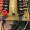
After reading a few past posts, it gets a lil confusing, which tvs is best for a conventional layout that runs some new LC+ engines and hasnt gone digital yet, if i understand correctly, put these across terminals at transformer and at taps to buss drops

Part numbers and pics are deeply helpful

Thanks in advance

Original Post

Replies sorted oldest to newest

Zener Transient Voltage Suppressor.  TVS.

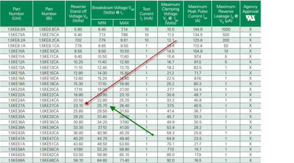
1.5KE27CA DO-201  (1.5KE27)  1500watt.   27volt.  clamps at 37 volts.  non-directional (doesn't matter +-)

I get them on ebay.   cheap.

Conventional; mount across + -  leads to track between transformer and track.

Digital; mount between transformer brick leads + - and before control unit (DCS, etc.) 

I also put one in each of my LED lighted passenger cars, or anything that requires power.

Last edited by Former Member

 TVS (transient voltage suppressor) across old pw ZW terminals or, as protection on terminal strip equipped with plate jumpers for railpower distribution to multiple track locations. White marked wire from 180 powerhouse is common, green is hot, protecting 5 energized screw heads each side. On layouts with long ovals/ power districts I soldered railpower conductors to every 37" section of Gargraves flex track and between track switches in the Service yards,etc. Thus,  protected distribution strips. I agree with Gun Runner's specification on the TVS.

If you are operating modern engines from a pw ZW  a TVS is a good idea.


IMG_1764IMG_2072

Attachments

Images (2)
  • IMG_2072
  • IMG_1764
Last edited by Dewey Trogdon
Engineer-Joe posted:

So how do you know when to replace them?

Failed shorted, would be easier to identify. Is that common? Do they just fail open? Could we connect a light to them?

Without some pretty sophisticated test equipment, you don't know when they are worn out, and they do wear out.  However, unless you are having all kinds of voltage surges often, in normal "train" use they will last a life time.

gunrunnerjohn posted:

I actually recommend a higher value for the clamping voltage for O-gauge model train use, the 1500W 36V TVS at Digikey.  The 27V model can clamp at too low a voltage for O-gauge use.  Peak voltage for 18V RMS is 25.45 volts, very close to the minimum breakdown voltage of the 27V TVS.

tvs


I asked an electrical engineer friend of my son who designs electric motors for specific needs and he told me I wanted a TVS that was just above the maximum constant operating voltage of the system.  He said a TVS just begins to break down at that rated voltage and actually clamps at a higher voltage.  So 27 volts is just above 25 volts but it doesn't really clamp down until about 37 volts.  He said too high a clamping voltage is like no TVS at all.

You don't want to be in the breakdown area at all.  The spikes you're really worried about are considerably above the clamping voltage of the one that I posted.  The maximum clamping voltage of the 27V one you specified is 37 volts, that's a specification maximum.  Perhaps this reference for selecting a TVS will help.  Note that they specifically state that the peak voltage in the circuit should NOT be greater than the Reverse Standoff Voltage Specification.  For your 27V TVS, that's 23.1 volts, considerably less than the 18V RMS  peak of 25.45 volts.  Another factor is many transformers, including some Lionel transformers, actually put out 19 or 20 volts, and some MTH transformers even more.

How To Select Transient Voltage Suppressors - Microsemi


I do occasionally know what I'm talking about.

gunrunnerjohn posted:

You don't want to be in the breakdown area at all.  The spikes you're really worried about are considerably above the clamping voltage of the one that I posted.  The maximum clamping voltage of the 27V one you specified is 37 volts, that's a specification maximum.  Perhaps this reference for selecting a TVS will help.  Note that they specifically state that the peak voltage in the circuit should NOT be greater than the Reverse Standoff Voltage Specification.  For your 27V TVS, that's 23.1 volts, considerably less than the 18V RMS  peak of 25.45 volts.  Another factor is many transformers, including some Lionel transformers, actually put out 19 or 20 volts, and some MTH transformers even more.

How To Select Transient Voltage Suppressors - Microsemi


I do occasionally know what I'm talking about.

Well, this is one we will have to agree to disagree on. 

Pine Creek Railroad posted:

Gentlemen,

   Just upgrade to running DCS, it has built in TVS that has worked for me for years.  No need to argue.

PCRR/Dave

Sure spend $300 plus for a lil protection, when all i run is postwar and a new lionchief plus or 2, all this added protection isnt even for the postwar stuff, you cant hurt em, i simply wanted a lil protection and piece of mind for the new 726 Berkshire i purchased this year, $4-500 for an engine isnt anything im going to do regularly, much less over $1000 for the legacy steamers, not when its likely all this newer stuff will end up trashed long before postwar gives up, most of my fleet is 60- 70 years old and still running strong, oil and grease, run em hard week after week, tremendous amounts of fun and laughter,  havent seen any new stuff stand up to the way they used to make em, its all go digital and keep throwing money at it...you need this, you need that, not to mention the cost of the locos, nice ones...forget that, i gladly spend spend a few bucks on tvs for the new stuff i run, added protection, but going digital for protection is counter productive, everyone here still says add tvs to that system too, not the answer i was looking for, thanks anyways..i appreciate those that have given great information.

Happy RR

TedW posted:

Here’s a couple photos, but you can connect them across a lockon, or between center and outside rail at a power drop connection.  Given your comfort zone inside the engine from power pickup to chassis.  Your choice of location.

BB6565E3-86E1-4684-A31C-024AC4E68D9F

87423CC2-8449-4963-9173-C850BA34A5B7


so if I install them across my ZW terminals as pictured will that be sufficient or they need to be installed at the point of track connection too?  thank you

Let me ask a couple of questions. 

If I were to install the exact same spec 33v TVS between the transformer and TIU as MTH installs in the TIU, which would clamp first, or would they both clamp at exactly the same time? 

In a severe voltage spike, which would fry first, or would both fry at the same time?

Last edited by Former Member
gunrunnerjohn posted:

I actually recommend a higher value for the clamping voltage for O-gauge model train use, the 1500W 36V TVS at Digikey.  The 27V model can clamp at too low a voltage for O-gauge use.  Peak voltage for 18V RMS is 25.45 volts, very close to the minimum breakdown voltage of the 27V TVS.

tvs


Thanks for this. What gauge wire are at the ends of these? Was thinking of using disconnects at each end to connect to FT. Then I don't have to solder.

gunrunnerjohn posted:

Due to the tolerances in the trip, and also the source of the spike, one would probably trip first.  Obviously, if a spike had enough energy to vaporize the junction in one, the other one would see it.

Exactly.  And there is no way to know if the TVS in the TIU or the external add-on TVS would be the one to trip first if they are the same spec.   Temperature and manufacturing tolerances play a role.  Same with which one would fry first in a big spike.

I was aware that MTH had settled on a 33v TVS in the current production TIU's after some experimentation.  And I was told that the only way to be reasonably sure the MTH internal TVS was protected was to go down a little in voltage on the external one I would install.  That's why I settled on a little lower voltage.  I would rather the external one fry which I can easily replace. 

I was also told that a TVS can fail, or it can simply degrade; that it is a maintenance item.  But I have no way to test if it's degraded.  (Shorts or fusing are easy to test for).  I know I can't test the TVS's in the TIU at all.  But I can change out the external ones on the TIU channels if I have a few derailments, or even yearly as a precaution. 


Dewey Trogdon posted:

Deuce: 

18ga as checked on my ancient stripper. Supplied by Mouser Electronics, others could vary, 1.5KE36CA stamped on the TVS, (1500 watts, 36 volts, CA=bidirectional) readable if you use magnification.


IMG_2071-001

Thank you Dewey. Bought a 100. That should last me a bit.

They have a number of them listed, I grabbed the STMicroelectronics ones. 34.2V breakdown voltage, 30.8V working voltage, and 64.3V clamping voltage. Will those work*? The Littelfuse ones clamp at 49.9V, otherwise their specs are similar.


*Nevermind. I looked back at the specs that GRJ posted and changed my order to the 49.9V clamping voltage ones.

Last edited by Deuce
gunrunnerjohn posted:

I actually recommend a higher value for the clamping voltage for O-gauge model train use, the 1500W 36V TVS at Digikey.

GRJ, are there any differences between the TP1.5KE36CA (Digikey part # F7614CT-ND ) that you mention above and the 1.5KE36CA (Digikey part # 1.5KE36CALFCT-ND) that you are aware of? The former's application is listed as automotive and $0.17 more than the latter, whose application is listed as general.

TIA,

Matt

Definitely down GRJ's spur and not mine, but an interesting thought. I will also be interested in GRJ's thoughts on this. Knowing when a TVS goes bad has been a topic of discussion here on more than one occasion. Also someone above suggested a light bulb, but I guess that would only show when the TVS was open and not each time it was spiked? Both interesting ideas.

As I recall from previous threads there is no good way to tell the status of a TVS unless you have specialized or sophisticated equipment. To me 'specialized or sophisticated' = $$$$ !!  Even if I could afford it I probably wouldn't know how to use it?

Or, maybe when you trip a breaker, I wonder if it would just be safe to say that all of your TVS' on that power supply had been stressed and skip the other stuff?

Last edited by rtr12

Actually, there's no simple test for an open TVS.  Unless they're pushed past their triggering limit, they should always appear as an open circuit.

To test a 36V transient diode, you need a power supply that at least can go up to 40V and with a current limiting feature. First set current limit to 20-25mA.  Connect TVS leads to positive and negative terminals.  With a bipolar TVS, polarity isn't an issue, with a unipolar TVS, you need to observe the polarity.  For AC, we're using a bipolar model. 

Slowly increase the voltage from zero to 33V and observe the current meter as you increase the voltage. It should not show any current reading.  Continue to increase the voltage and near the 36V value the current meter should jump and read 25ma, you've reached the break down voltage. If you continue to increase the voltage past the breakdown, the current meter should continue to indicate 25ma.  Then reduce voltage slowly, as soon as it reaches under the breakdown voltage of around 36V, the current meter again drop to zero current.

That's what you see if you have a good TVS.  If you have a shorted one, it's obvious, you always get 25MA from the very start.  If you have an open one, you'll get no current at any voltage.  Finally, in rare cases, they can partially fail, and you may get different results, perhaps less current, or a breakdown at the wrong voltage.

It should go without saying, but all these tests are done on a TVS that is NOT in the circuit, it should be totally disconnected.  In circuit tests of a TVS are not recommended for obvious reasons!

Last edited by gunrunnerjohn

I am satisfied that the inexpensive transient voltage suppressors suggested by GR John and others that I have been using for years now are satisfactory voltage spike protection for my toy train engines. They are far better protection than the expensive PowerGuards that I bought way back in the early Forum days.  I donated one of mine to Dale Manquen (RIP) for an autopsy and he concluded that it was not near as effective as a 50 cent TVS.  With tongue in cheek he noted that I could still use them as $85 pilot lights to indicate layout district power status........so, see two "pilot light" PowerGuards above the meters in my crude attic control center:


IMG_1782-001


Attachments

Images (1)
  • IMG_1782-001: Control center
Last edited by Dewey Trogdon

Add Reply

Post

OGR Publishing, Inc., 1310 Eastside Centre Ct, Suite 6, Mountain Home, AR 72653
800-980-OGRR (6477)
www.ogaugerr.com

×
×
×
×
Link copied to your clipboard.
×
×