


|
|
Replies sorted oldest to newest
quote:Could someone who already has these, please help me out:
• Approximatley how big are these new control switches (foot print)?
quote:
• Are the connection points accessible from the bottom of the switch?
Don't know yet.quote:• Do the the red and green LEDs remain lit (as the DZ1000 control switches) to indicate the last position actuated, or do they light up just while the push button is kept depressed?
Thanks!!
Alex
quote:• Do the the red and green LEDs remain lit (as the DZ1000 control switches) to indicate the last position actuated, or do they light up just while the push button is kept depressed?
well the installer should have the switch machine positioned to the correct nomenclature on the switch button itself. The button is designed like a CTC machine switch button would have been.quote:Given that there is power fed in from side, I am guessing that the light circuit is an independent circuit, divorced from the switch contacts circuit. That is, the red or green lights depending on lever position but does not indicate the actual switch machine position.
Sam
quote:Although I'm sure most of us can figure out how to wire this, wouldn't it be nice if Atlas O put a printed diagram on the back of the package for those who are less electrically savvy?
quote:OK, dumb question but... I have never figured out... just what does a non derail board actually do?

quote:Originally posted by DPC:
Well a least it's got an indicator light and looks a whole lot better than the 40 year old cheesy one with the blue button
David
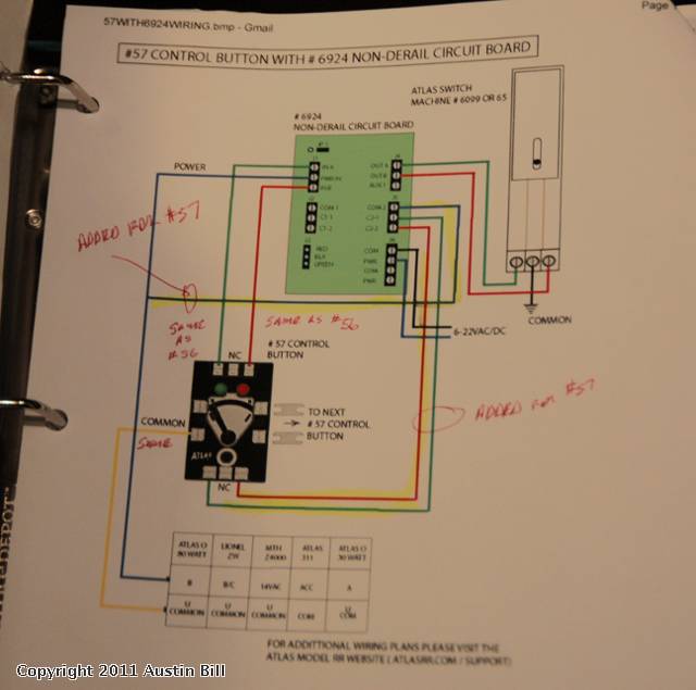
quote:Originally posted by Austin Bill:
Hi Guys, I just finished successfully installing my first #57 switch controller. Works great. Leds are bright and the lever and pushbutton action seem much more precise than with the old #56's.
If you use the #6924 Circuit boards to control your Atlas O switches and provide other functions such as non-derailing and dwarf signal activation -- as I do -- then the #57 wiring is different.
Below is the wiring diagram Steve Horvath sent me on how to do it. Please pardon the photo quality as I'm busy wiring new #57's!!
Access to this requires an OGR Forum Supporting Membership
