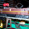
I recently acquired a single-motor Williams E-60 electric locomotive.  I run conventional and would like to add a second power truck but do not know how to wire the second truck so that they both pull in the same direction.  A step-by-step how to would be greatly appreciated.


Joe

Original Post

Replies sorted oldest to newest

Joe:  If you are able to get a second power truck with a motor, be sure that the two motors are identical.  Different motors have different RPM and torque characteristics which would cause problems if they were run together from the same electronics.  Williams engines tend to run and start at lower voltages than other engines and if you do have identical motors, you can connect the two in series rather than parallel and lower their starting speed.  I recommend this practice on all two motor Williams engines because it greatly improves their performance characteristics.  They start more smoothly and still have all the top speed characteristics that you could want.


The way to determine the wiring for two motors is pretty much experimental.  Take one of the leads going to the existing motor, connect it to one of the terminals on the new motor and simply connect a wire between the two open terminals on the motors.  If the motors are correct, the engine will run just fine in both directions.  If the motors are wired backwards, you will see the two motors "fighting" with one turning one direction the other in the other direction and the engine won't go anywhere.  If that happens simply reverse the two leads going to one of the motors.


If you are going to use TMCC or DCS on the engine, you might not need to wire the motors in series.  I still wire many of my engines with motors in series, simply because it makes for very smooth starts and excellent slow speed performance.


Hope this helps.


Paul Fischer

These are DC can motor units - like most modern locos use - and once you mount the second power truck, run two wires from the reversing unit from the same terminals/

connections on your board as the existing motor wires, or using wire nuts, splice your new wires into the existing motor's wires, put it on the track and try it. If the new motor runs the wrong direction, simply reverse your splices. DC direction is based on polarity (+/-) and has only two possible connection combinations; you can't hurt it.


These are neat locos, even if they aren't scale length (the girth is correct, I believe)

and have the wrong trucks. They look very convincing; I'd love to see one with Command. 

Just for info. I bought one of these when they first came out from Williams. This was about a thousand years ago. They were a kit then with no trucks. You had to supply the Lionel four wheel trucks. Other than the Trainmaster Lionel didn't make six wheel trucks at the time. The engine looked kind of silly with four wheel trucks but there was nothing else to use. As soon as the SD-9 came out I bought the new six wheel trucks as parts from Lionel and replaced the old trucks on my E-60. It looked much better. Don

C.W. you hit it right on the head.  It has a single 4-wheel MPC Lionel power truck.  I have an MPC Great Northern U36B that i was going to put the shell on a new Williams GP Frame so I may already have a donor power truck.  They look the same.  Would they have thew same RPM and torque characteristics that Paul was talking about?


Scale Rail, when I first got the E-60 I looked for some photos but didn't realize they were six wheel trucks.  If the U36B donor doesn't work out maybe I'll try to get some six wheel lionel trucks.


The kits came with an adaptor plate for use with the dummy truck when a single motor setup was installed.

I think the adaptor plate is held in by four screws.

Just remove the plate, and install a second motor.


Those motors have two flat mounting posts. These posts fit into slots in the chassis.

Place the motor on the frame. A cup washer is put over the posts (flat side towards the frame), followed by a spring, and finished with a tinnerman's clip to hold everything together.

I have a block that fits between the wheels to support the motor while setting the tinnerman's clip.

I use a socket of appropriate size as a tool to drive the clip in place.

I rap the back of the socket with a soft tipped hammer.

I like to put the clip on just enough to lock in place.

If you drive it further, that's OK as long as the motor swings and can rock.

If things are too tight, you may have issues with derailments.

(Not a big deal, just remove the clip and try again).

I don't try to reuse the clips.

The Train Tender sells them for 15 cents each when you buy a minimum quantity of twentyfive. 


Wiring should be straightforward.

Connect the power wires from rollers on both trucks together.

Connect a jumper wire between the fields.

Connect jumper wires between the brush holders.

The brush holder wires should go parrallel to the edge of the frame.

This will make the motors run in opposite directions when viewed from the coupler end of the motor (towards the coupler versus away from the coupler), but that is what you want.

If they don't run to work together, just exchange the wires on one brushplate.


One last thought:

I would try to find as close of a match as possible for the second power truck.

There are variations in the construction of the MPC Geep power trucks. For example, older trucks do not have a set screw on the brushplate. Some MPC power trucks have a pointed set screw, which can wear a dimple into the top of the armature shaft. When the dimple gets deep enough, it can slow down the motor a bit.

I've replaced those pointed set screws with flat ones to eliminate the issue.

Last edited by C W Burfle

I had no idea that you were dealing with a loco this old - a Williams body on a Lionel

frame, so my advice was useless, anyway.


Mine is the modern one with Williams E-7 diesel trucks and easy-to-handle DC

motors. They run pretty well, and can be found fairly cheaply sometimes. 


BTW, johnsgg1: being an electric, the E60 wouldn't have a "fuel tank", and I think that

these had HEP for car heating/cooling, rather than a steam boiler - which would have

indeed needed a smallish fuel tank of some kind, somewhere.

The Amtrak E60's were originally built in two versions:  some with HEP, some with steam generators for 'heritage' stock, especially through trains to/from "the South".  The plan was for the latter to be gradually converted to HEP as steam heat was "phased out" [ pun intended ].


I think the "large fuel tank" captures the look of either version rather well, generally speaking.


Best rgds, SZ

Attachments

Images (1)
  • 1987005
Last edited by Steinzeit

Hi:  Just a note of caution - in earlier times, MPC did not follow the wire color codes of old Lionel Corp. as regards placement on the e-unit finger boards. In some Lionel Corp. units, only yellow and black wires were used. In more rescent times LTI/LLLC have indicated that in production, wire colors were sometimes substituted, so it was necessary to trace out the wires to be sure that they were going to the place intended.


      As regards mechanical e-units: when looking at the side opposite the switch lever (backside) at the fingers themselves; From right to left reads as follows:

          extreme right finger - usually black or red - power feed from track,

          second/third finger  - usually  blue          - feeds one brush connection

          last finger/left         - usually  green         - feeds the motor field connection


          two finger on bottom - usually  yellow       -  feeds the other brush connection


MPC  during some production runs of e-unit finger wiring assembly would switch the colors of the Blue and green wire positions and have them in the opposite locations. The color of the wire is not important, but rather, what and when, current is passing through them.


       Another thing MPC did was to use white wire with a color trace line on it: right side would be  wht/blk trace, next wht/blu trace, next wht/grn trace, and lastly wht/yel trace.

If a color was run out then one of the other colors would be substituted, so placement by position is what is important.


       Some Lionel Corp.  three position e-units used in the sheetmetal alcos would only have two colors in their wiring: 2 yellows for the brushes and  2 blacks for the feed to the fingers and the motor field.  Again where the wire is going is what is important, not color.

Some GGI's had all black wire on their e-units, and jumpers to the second motor.


       Simple guide:  Right side - power feed,  two center wires (upper/lower) one to each of the brushes, and  left to the motor field.  With the exception of two or three special e-units , this guide is golden.


       When connecting a second motor to the first, their brushplates will sit back to back - mirror images. Just run extending wires, in a straight line, from one motor brush terminal to the other motor terminal, and connect the fields (middle wire). this will set the motors up to run: one forward and one reversed, so that they run together.


       Lastly, the mechanical e-unit has no default  to run position, it just cycles around in it's infamous  fwd.- neut.- rev.- neut.- fwd.  Amen. Hope this helps.   Dennis M.

PRRHorseshoeCurve: at the moment I can't remember what engine the trucks were for.  At the time I was doing repair work for a couple Lionel service stations in Fayetteville, NC and I ordered the trucks from Lionel's parts department.


I still have the receipt - somewhere.  When I get home I can look for it.


The steps on the front don't line up with anything, but still I liked the overall look.


Post

OGR Publishing, Inc., 1310 Eastside Centre Ct, Suite 6, Mountain Home, AR 72653
800-980-OGRR (6477)
www.ogaugerr.com

×
×
×
×
Link copied to your clipboard.
×
×