I have a two light, three wire signal tower with red and green lights that I would like to use with a Lionel FasTrack Remote Switch. Is there a way to connect the signal to the remote switch so that the lights switch between green and red? I just realized I left out the fact that this is a FasTrack switch.
Replies sorted oldest to newest
It can be done, with a couple of diodes and LEDs to mimic the switch controller indicators. I would have to experiment to get it right.
@ADCX Rob posted:It can be done, with a couple of diodes and LEDs to mimic the switch controller indicators. I would have to experiment to get it right.
The Signals that I have use AC since I tried a 9 volt battery and got nothing but when I touched the signal to an AC source they lit up. I'm wondering if I could use some sort of relay wired to the Fastrack Switch so that when you throw the switch it it also throws the relay which would switch the light that's being lit?
You could use latching relays activated(& released) by the trigger rails on the switch. A 022 switch machine mounted under the table would be simpler still.
I am sure you can do it with an Atlas 200 relay. I used these on my reverse loops and they should work for what you have in mind, not cheap, $12.00 -$15.00 each but pretty simple hook up.
Ray
I believe that the LEDs in the switch (turnout) controller receive a positive or negative 5 volts from the yellow and black wires to indicate the position. You should be able to tap into those to operate your signals.
Leo is correct, this could be done with a fairly simple circuit, a low current 5V coil relay and a diode comes to mind. For instance, I have some 5V coil relays that have a 10ma operating current, I'm guessing I could probably use the LED output directly to activate them, a diode would make them directional. In the worst case, I'd have to add a transistor or FET driver to provide more current if the LED output isn't up to the task.
@gunrunnerjohn posted:Leo is correct, this could be done with a fairly simple circuit, a low current 5V coil relay and a diode comes to mind. For instance, I have some 5V coil relays that have a 10ma operating current, I'm guessing I could probably use the LED output directly to activate them, a diode would make them directional. In the worst case, I'd have to add a transistor or FET driver to provide more current if the LED output isn't up to the task.
What would this circuit look like? I am fairly familiar with components but don't have to the skills to figure how things would go together to work. Could I tie the relays into the underside of the switch, connecting them to where the wires go in that are operated by the throw bar? I would like to have it work where I throw one switch and both the turnout and the signals change. I'm trying to find wiring diagrams but I'm not finding anything....
Just to be clear, your signal lights have incandescent bulbs (not LEDs)?
No one has posted (on this thread anyway) how much current the FasTrack yellow wire can provide and whether it can directly drive your two-light signal (if it's LED) or a "low-current" 5V relay if you need a relay to switch the higher-currents needed to drive incandescent bulbs.
There are low-cost relay modules (~$2 each on eBay) that have the transistor drivers already installed to activate the relay with low-currents - no soldering required but there are details. What is your intended power source for the switch and the signal?
The Fastrack yellow wire is a signal wire, I'm sure it's not capable of much current. That's why I suggested a low coil current, and perhaps even a transistor or FET driver.
@stan2004 posted:Just to be clear, your signal lights have incandescent bulbs (not LEDs)?
No one has posted (on this thread anyway) how much current the FasTrack yellow wire can provide and whether it can directly drive your two-light signal (if it's LED) or a "low-current" 5V relay if you need a relay to switch the higher-currents needed to drive incandescent bulbs.
There are low-cost relay modules (~$2 each on eBay) that have the transistor drivers already installed to activate the relay with low-currents - no soldering required but there are details. What is your intended power source for the switch and the signal?
The signal lights are LEDs. I opened up the throw bar switch with the two momentary buttons and touched the ground wire of the signal light to ground and one of the LEDs to one of the LEDs on the switch board and got no response but when I touched the wire to one of the wires going to the switch it worked but it doesn't work to switch the lights from green to red.
@Brendan posted:
Where does the wiring go for the signal?
@Roger Elliott posted:...The Signals that I have use AC since I tried a 9 volt battery and got nothing but when I touched the signal to an AC source they lit up.
I'm still not clear on what you have.
You have a 3-wire signal that has a red and green LED (not bulb).
You want to connect the 3-wire signal to a FasTrack Remote Switch to indicate switch position.
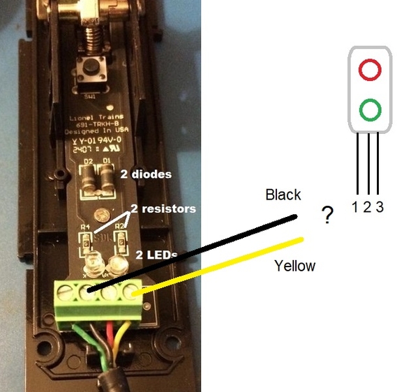
You are using a Controller (guts of which shown above left, photo from this OGR thread) with a 4-conductor cable to the FT switch.
The issue is how to connect the Yellow and Black wires to your 3-wire signal depicted above...and what components (relay, resistor, etc.) might need to be added.
Correct any of the above. Then here's my questions:
Did you open up the 3-wire signal and can you post a photo of the guts...or post a schematic if you have one...or give us a manufacturer item # if it has one?
You say you hooked up a 9V (DC) battery to the 3-wire signal and nothing lit up...but then you hooked up AC and "they" (both?) lit up. For these tests, which wires (call them 1, 2, 3) did you apply the voltages to and did you try all combinations in both directions when using DC? In other words, for 9V battery 1-2 and 2-1, then 2-3 and 3-2, then 1-3 and 3-1. For AC, it's OK to simply test 1-2, 2-3, and 1-3.
For the AC cases, I assume this was a train transformer and what was the voltage setting?
Attachments
@stan2004 posted:I'm still not clear on what you have.
You have a 3-wire signal that has a red and green LED (not bulb).
You want to connect the 3-wire signal to a FasTrack Remote Switch to indicate switch position.
You are using a Controller (guts of which shown above left, photo from this OGR thread) with a 4-conductor cable to the FT switch.
The issue is how to connect the Yellow and Black wires to your 3-wire signal depicted above...and what components (relay, resistor, etc.) might need to be added.
Correct any of the above. Then here's my questions:
Did you open up the 3-wire signal and can you post a photo of the guts...or post a schematic if you have one...or give us a manufacturer item # if it has one?
You say you hooked up a 9V (DC) battery to the 3-wire signal and nothing lit up...but then you hooked up AC and "they" (both?) lit up. For these tests, which wires (call them 1, 2, 3) did you apply the voltages to and did you try all combinations in both directions when using DC? In other words, for 9V battery 1-2 and 2-1, then 2-3 and 3-2, then 1-3 and 3-1. For AC, it's OK to simply test 1-2, 2-3, and 1-3.
For the AC cases, I assume this was a train transformer and what was the voltage setting?
The picture you have matches what I've got right now. I have the exact switch unit which which you have pictured and the signal has three wires. A red one for the red light and a green one for the green light and a black wire for ground. I am running 12v ac which runs the switch just fine. Someone suggested the Atlas snap relay tied into the switch for the turnout and then having the signal tied into the snap relay so when you throw the switch the signal will switch from red to green and back again.
OK. I understand that photos/diagrams/specs of your 3-wire signal may not be practical for you to post.
I'm still looking for more information about the signal itself. Previously I asked about your experiment. It's re-stated below with the wire colors BLK, RED, GRN for your mystery signal.
You say you hooked up a 9V (DC) battery to the 3-wire signal and nothing lit up. The battery of course has a + and - terminal and should even be labeled as such. So for the 9V test are you saying no light for:
a) BLK to -, RED to +
b) BLK to -, GRN to +
c) BLK to +, RED to -
d) BLK to +, GRN to -
But then you did get light for 12V AC:
a) BLK to common, RED to AC hot
b) BLK to common, GRN to AC hot
@stan2004 posted:OK. I understand that photos/diagrams/specs of your 3-wire signal may not be practical for you to post.
I'm still looking for more information about the signal itself. Previously I asked about your experiment. It's re-stated below with the wire colors BLK, RED, GRN for your mystery signal.
You say you hooked up a 9V (DC) battery to the 3-wire signal and nothing lit up. The battery of course has a + and - terminal and should even be labeled as such. So for the 9V test are you saying no light for:
a) BLK to -, RED to +
b) BLK to -, GRN to +
c) BLK to +, RED to -
d) BLK to +, GRN to -
But then you did get light for 12V AC:
a) BLK to common, RED to AC hot
b) BLK to common, GRN to AC hot
Yes basically any combo of wires to + and - on a 9volt battery got me nothing. But using AC with BLK. to common, red or green would light up just fine.
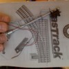
Here's a photo of the signal and the manual for the switch
Attachments
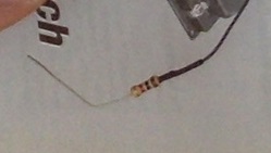
OK, we are making some progress! So that component shown in photo has 4 colored stripes that look like (right to left) BROWN - BLACK - something - GOLD. Is the something BROWN, RED, ORANGE, or ?
And is/was there any possibility that with the 9V battery test that the lights might have been on but VERY DIM? By very dim I mean maybe you need to turn off the room lights to see it.
Attachments
Do you have a multimeter and comfortable using it?
And, with absolutely no intent on being a wiseacre, do you know your 9V battery is good? I hope you don't say you did the "9V battery tongue test"! ![]() Google it for a good chuckle...
Google it for a good chuckle...


