Originally Posted by Mark B:
Originally Posted by Mike CT:

A good location for a fuse, it would protect just about every thing in this discussion. Try it, see how it works for your operation. You may want to revisit this thread and tweak the fusing/fuse location(s) later.

Thanks Mike.  Very helpful comments!!!.  Excellent thread. One the fuse's, I think I will try this....in the following order of installation:

1)  7.5 AMP Fuse at MTH BB Blue PWR line in form KW.  Is 7.5 correctThe Atlas boards are rated at 8 amps.   sounds like this will protect everything downstream.

2)  J5 COM 2: 3 Amp per atlas diagram. Yes, Derails and shorts can damage the 6924 relay board that is used for power routing.   Do I need this since I'm NOT using Power Routing wires on most of my switches  (036-054).

         ---2 Sets of 072 switches for moving trains from my A line/loop to B line/loop. Will these need power routing? It depends on the roller pick-up spacings of all your engines. Each engine is different. They may all work. You may have one or two that don't.  Try the switch combination first see what happens.   will of course be wiring them in pairs like your #17 & #18 switches.


Thanks Mike.

I picked up a 7.5 Amp fuse and housing today for the KW power line into MTH Buss Board. 

Since I'm not wired for Power Routing, I'm not sure if I need to install a 3 Amp fuse on J5 COM 2 for each #6924. Possible to use a 3 Amp in place of my 7.5 Fuse?  Would certainly cover things.....even though I might have to replace the 3A with every derail. Make sense?

Mark B.
Hi Mike/Steve:
 
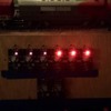
I've got 6 units hooked up.  Everything operates correctly.....most of the time....except a couple odd things (SEE 2 PICTURES below of #55 1-6 and the 6 NEW 6924's):
 
1)  As train goes around, ie., Loop B, switch 1/6924, will trigger to red and ie., also another one like switch 3/6924.  I quickly reset to green and it's fine for a awhile or happens soon again.  This doesn't effect anything in terms of shorts or loss/gain, of power.  
---------In wiring up #57's, some have different J4 or J5 arrangements on the red & green wires to get the #57 lights to line up with switch closed or open.  Perhaps this is the problem?  Something in the track electricity flow in either COMMON RAIL or MIDDLE RAIL could be spiking/interrupting flow and thus an event.  Ideas?
 
2) JP 1:  should the little black cap be off, on on e pin or both.  It doesn't seem to make a difference either way.  Pretty sure the JP 1 is for switch light operations.
 
3)  #57's 1 through 6.  3 to 6, the RED lights burn much brighter than 1-3.  Bought them for different OGR members. 3-6 appear to be a different 'set' than 1-3.  Could this be due to an upgrade or change in Atlas's RED LED bulbs being upgraded/changed at factory?
 
Thanks!!!!


Mark
 
 
Originally Posted by Mike CT:
Originally Posted by Mark B:
Originally Posted by Mike CT:

A good location for a fuse, it would protect just about every thing in this discussion. Try it, see how it works for your operation. You may want to revisit this thread and tweak the fusing/fuse location(s) later.

Thanks Mike.  Very helpful comments!!!.  Excellent thread. One the fuse's, I think I will try this....in the following order of installation:

1)  7.5 AMP Fuse at MTH BB Blue PWR line in form KW.  Is 7.5 correctThe Atlas boards are rated at 8 amps.   sounds like this will protect everything downstream.

2)  J5 COM 2: 3 Amp per atlas diagram. Yes, Derails and shorts can damage the 6924 relay board that is used for power routing.   Do I need this since I'm NOT using Power Routing wires on most of my switches  (036-054).

         ---2 Sets of 072 switches for moving trains from my A line/loop to B line/loop. Will these need power routing? It depends on the roller pick-up spacings of all your engines. Each engine is different. They may all work. You may have one or two that don't.  Try the switch combination first see what happens.   will of course be wiring them in pairs like your #17 & #18 switches.


6 Atlas 6924's

6 Atlas boards

Attachments

Images (2)
  • 6 Atlas 6924's
  • 6 Atlas boards
Last edited by Mark B

Mike/All......I'd like to use J3 on the Atlas Non Derail board for MTH Siding Signal-red, yellow, green. Problem is my boards have then pins to attach Red, Green, Black. J3 seems to lack solder less jack like J1, J2 etc.

Ideas? Not even sure above works. Simply avoiding having to wire up 12V Relays, Rectifier etc.

Mark 

Just ideas for connections here, I do not know if these will work with your MTH signals? But, Ebay has connectors with wires attached that will fit the 6924's pins. Same as connectors on computer fans. Wire colors probably won't match the 6924's markings as I think they are usually red, black and yellow wires. That is what I use for some things like this. You could connect wires to a terminal strip. Search for: 2.54mm 3 Pin Female Connector

Arduino type 0.1" female connectors will also work, but you have to solder wires to their pins. (0.1" - same as 2.54mm)

I don't have any of the MTH signals, so I have no idea how they operate.

Last edited by rtr12

A better choice would be to use J2 connector. As long as your not using this connector for another purpose it would work fine for your application. The J3 connector is the interface to use the original # 6931 dwarf signals if needed. For the J3 connector to be active JP-1 would be connected across the shorting pins. Unless you are using the dwarf signal I suggest you use the J 2 connector. If you have  a question you can reach me at  908-687-0880 Ext 7142 and I can explain in more detail.

Steve H


Steve Horvath posted:

A better choice would be to use J2 connector. As long as your not using this connector for another purpose it would work fine for your application. The J3 connector is the interface to use the original # 6931 dwarf signals if needed. For the J3 connector to be active JP-1 would be connected across the shorting pins. Unless you are using the dwarf signal I suggest you use the J 2 connector. If you have  a question you can reach me at  908-687-0880 Ext 7142 and I can explain in more detail.

Steve H


Hi Steve,

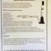
Attached is the Operating Instructions for the MTH Vertical Signal that I plan on wiring up to J2 (COM 1, C!-1, C2-1).  Signal operates, such as: Red turns to Yellow for 5 or 10 seconds and then to Green.

Need to confirm where Black (Common) goes......to Transformer U anywhere or U on #6924 wiring?

MTH Vertical Signal

Attachments

Images (2)
  • MTH Vertical Signal
  • mceclip0

Add Reply

Post

OGR Publishing, Inc., 1310 Eastside Centre Ct, Suite 6, Mountain Home, AR 72653
800-980-OGRR (6477)
www.ogaugerr.com

×
×
×
×
Link copied to your clipboard.
×
×