
Replies sorted oldest to newest

GG1 2340 posted:

I am in the process of wiring my Ross Switches (there's 9 of them). Is there any specific way to do this? Do I need a terminal strip or can I just run all the wires back to the power source? Any diagrams out there?

Thanks for any help.


Buzz

What are you wiring? the DZ switch machines?    You can use a common wire to feed the center  connection (hots) but then you need separate wires from the controllers that activate the switch. 2 wires.

you could use  2 terminal strips   one for the hot and and another for the  common (old term ground)  and locate it close to all the switches.... From the terminal hot strip you would feed the center connections on the DZ-1000. From the ground strip  you would feed the DZ -1002 .controllers.    The ground should be the same as the outside rail  if using the non-derailing feature.

   Ok what  are you using  to power  the layout and the switches?  That info would help a lot.

Last edited by Gregg

Hmm it would be so much easier if you could use the ZW for both... The U connection on the ZW  would handle the outside rail & be  the common for the DZ switch machines.   If you have a spare handle B 0r C that could handle the  hot for the switch machines. Dial the handle up to around 12/14 volts.  doable.

Now if the LW goes into the picture it has to phased together with the ZW. I'm not exactly sure how, so I'll leave that to someone else. 


Well that's up to you... Maybe get'em hooked up and get them working with the LEDs giving the correct indication of the  switch route  ( green  for straight and red for diverging), Then add the non'-derailing feature .  Just a couple more wires ) Sounds like a fun project and good luck... I don't use the non derailing feature  with tortoise machines but sometimes wish I had the feature.   Sure! hook them up.

Here are some pictures.  The switch motors are activate by a Lionel SC2 controller and two different sets of push buttons.   Power for the system is 18 volts AC. from a small HO power supply.

Seven push button sets for (7) sets of switches.  There are another (7) total of (14) pushbutton at a different location.

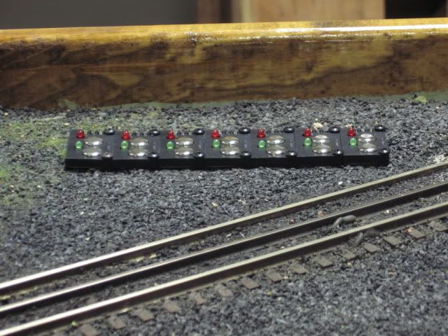
Each pushbutton has a green (through) and red (out) button.

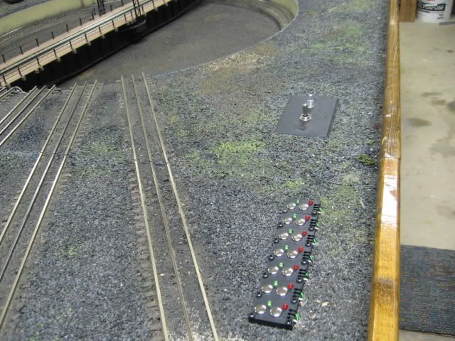
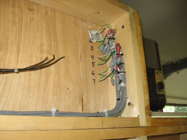
Note the push button wires under the layout, numbered 1 through 7.  Also pictured is the Lionel SC-2 controller.

The SC-2 controller will only accommodate (6) of the (7) sets of switches that I wish to control.

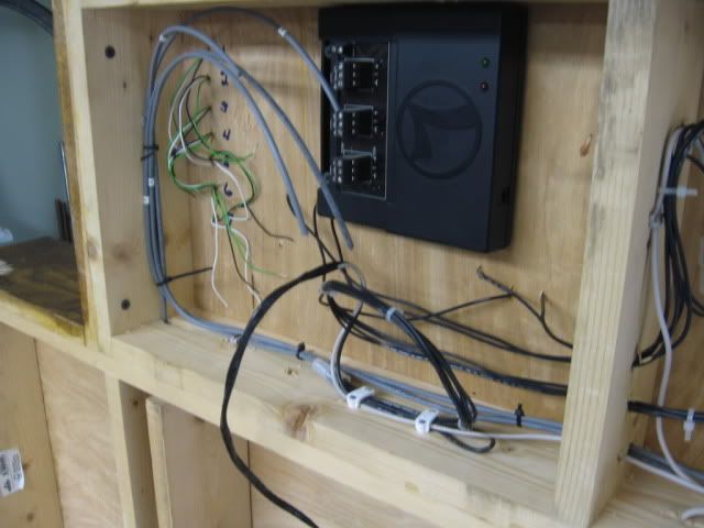
The other (7) pushbutton wires, right side of the turntable module.

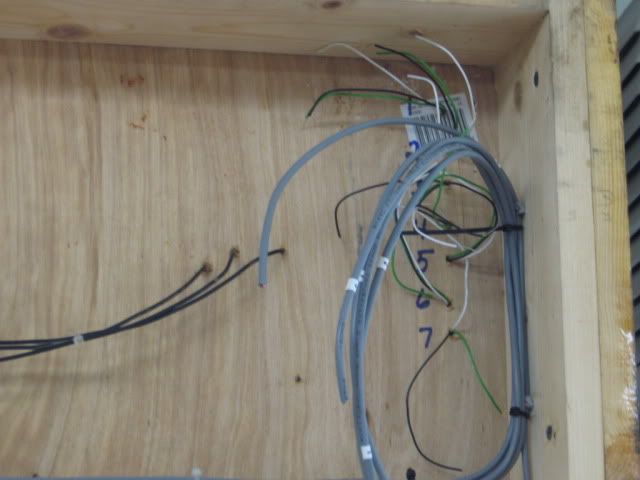
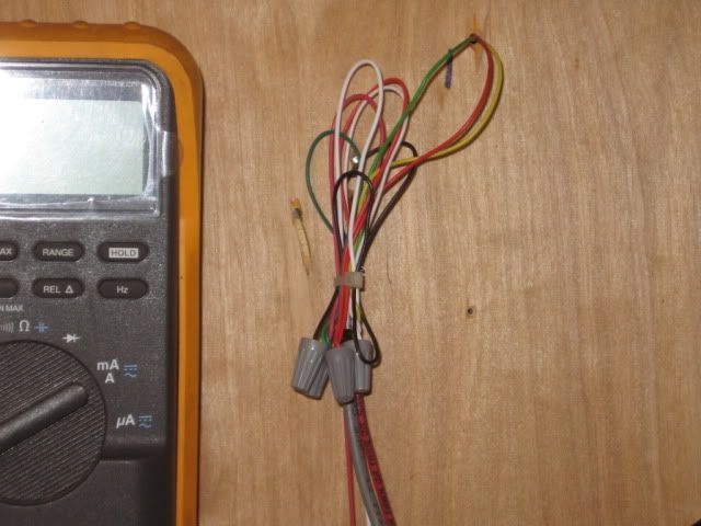
Each gray cable has (4) 22 ga. wires Black, Red, Green, and White.

Black is accessory and track common

Red is accessory power

Green is switch motor/push button lead (Through (Green). 

White/Yellow is switch motor/push button lead (Out (White/Yellow).

Accessory power is applied at this corner.  Note the red (power) and black (common) wires in this picture to the left.

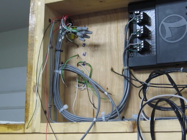
DZ 1000 switch motor leads under the table.  Keep in mind that most of this switching layout involves (4) cross-over pairs of switch motors. The double lead connection at this switch motor parallels power to the second switch motor of a cross-over pair.

Near the #1, Green from the switch motor to (2) greens from gray cables.

Red from the switch motor to (2) reds from gray cables.

Yellow from the switch motor to (2) whites from gray cables.

Black is capped off not connected at the Switch motor.  It is connected at the push buttons.

Completed push button and SC-2 wiring left side of the layout.  Accessory power is applied here.

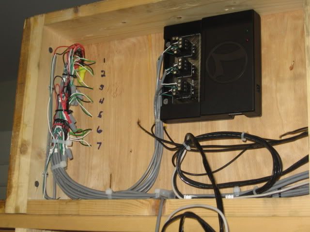
Completed push button wiring right side of layout.  Wiring from here is to the switch motors or switch motor pairs.


Last edited by Mike CT

WEST DISPLAY 006

Wiring your switch motors can be done many ways. I find the neatest and easiest method uses the still available 66M1-50 connector blocks. The display above shows how different switch motors and other components used in model railroading can be installed using the 66 block. You can also use the standard terminal strips , barrier type or European style to accomplish your goal. If you visit my website you will find drawings on how to wire the DZ 1000, DZ 2500, and DZ 1008 relays using 66 blocks. If you have many switch motors to wire you will see how to wire 16 Z1000 motors and controllers on one 66 block. Visit the site at www.montanarailpower.com


Attachments

Images (1)
  • WEST DISPLAY 006: Wiring switch motors with 66M1-50 Connector blocks
Last edited by Steve Horvath

Add Reply

Post

OGR Publishing, Inc., 1310 Eastside Centre Ct, Suite 6, Mountain Home, AR 72653
800-980-OGRR (6477)
www.ogaugerr.com

×
×
×
×
Link copied to your clipboard.
×
×