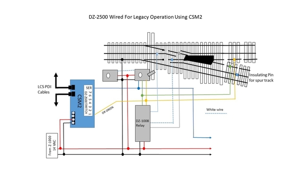
On long switches, like my Ross #6s and #8s, you need to power the closure rails to allow engines with short center rail pickup spacing to pass through them. Not sure how this is accomplished when using the CSM2 as part of the LCS.  Has anyone done this?

Here is how I was going to do it before the CSM2, not using the sensing function.  The yellow and green wires off the DZ-2500 were used to trigger the DZ-1008 relay. 

LegacySER2-DZ-2001-DZ2500

 Now here is the wiring diagram for the CSM2 from the manual.  The manual does not show how to wire the closure rails.

 DSC_0128

DSC_0132

Ideally I would use the Yel and Grn terminals on the breakout board (I have several from ERR) but they seem to be needed for switch sense.  I think I could also connect to the yellow and green wires where they connect to the board.

Any ideas/thoughts would be greatly appreciated.  Thanks.

Attachments

Images (3)
  • LegacySER2-DZ-2001-DZ2500
  • DSC_0128
  • DSC_0132
Original Post

Replies sorted oldest to newest

Tony H posted:

I use the DZ 2500 on all my switches and also use the CSM2, but don't use the break out board.  I already had the 1008 installed on two switches before I added the CSM2 and did not make any changes and it still works.  I did not see a reason to add the breakout board.

Tony  

Tony H posted:

The only thing I did when I added the CSM2, and I added 7, was attached the blue wire to to the CSM2.  I had the switches set up for a few years before adding the CSM2s

Tony

So basically you replaced the DZ-2001 Data Driver with the CSM2.  For sensing, it seems like you need to run either the green or yellow wire to one of the CSM2's switch positions.  It is that simple?  Here is what I think the wiring diagram would look like:

CSM2 Wiring Diagram-no board

I'll set this up soon on my test loop.

Attachments

Images (1)
  • CSM2 Wiring Diagram-no board

Ron-

I don't know if you're still dealing with the CSM2/DZ2500/DZ1008 but I just recently documented connection of all of that stuff so I can repeat it.  Long story short, you can connect the red/black/yellow/green wires to the breakout board in the spring-loaded connectors.  The BLUE 1008 wire needs to go to track power positive.  The Gray and White 1008 wires need to go to the appropriate closure rails; depends on direction. 

I'm also in the the process of testing the molex connector to the white connector on the breakout board to clean up wiring a bit.  I'm not sure if it will accomplish much but I'm just experimenting.  Jon Z gave me the connection part number and I picked up a handfull to try.


Tim

DZ 1008 latching relay is key.    As explained:  "The BLUE 1008 wire needs to go to track power positive.  The Gray and White 1008 wires need to go to the appropriate closure rails; depends on direction".

You may want to add a 5 amp fuse to this circuit.  O scale flanges and wheels rolling through any switch can be un-predictable at times.  A track power dead short on one of these small relays can be a problem.   

Contact Dennis Zander.    DZ for assistance.  

CAPPilot posted:

Tim,

Thank you!  I only experimented with two switches and could not get them to work properly.  I've taken down my test layout and now laying track for my "stage 1".   When I get back to the switches I'll take a look at this.  Can I get the part number for the connectors that Jon gave you.  If nothing else, I'll add them to my parts bin.

Ron-

My apologies for the delay in getting you the part number for the connector.  Here's the info from Jon Z.  I have yet to incorporate the connector and I don't have a wire color assignment code from Jon so there's some work to be done.

The 8-pin part number is digikey 455-1199-nd. Mfg PN is ZHR-8.

Tim

Add Reply

Post

OGR Publishing, Inc., 1310 Eastside Centre Ct, Suite 6, Mountain Home, AR 72653
800-980-OGRR (6477)
www.ogaugerr.com

×
×
×
×
Link copied to your clipboard.
×
×