I'm starting to plan a project for next fall, a train yard using the Ross 4 way 8 track yard set.  The idea is to have 6 yard tracks and use the two outer switches for a reversing loop.  The yard set has 7 turnouts  plus there is a turnout off the layout to enter the yard.  As a result there are 8 turnouts in total for yard operation.  Each turnout has two positions for a total of 16 possible turnout positions.   There would be 8 combinations of turnout positions to operate the yard:  a layout/non-yard position, a reversing loop position and 6 yard track positions.

I'd like to automate the 8 turnout combinations using a rotary selector switch.  For example, set the rotary switch to position 6 and the all the turnouts automatically flip to route the train to lane 6.  I have DCS and could us the routing function to accomplish this but at the moment I'm focused on the rotary switch idea.

Rather then reinvent the wheel, I thought I would ask the Forum for technical approach ideas ?  I'm thinking a digital solution, maybe a rotary switch encoder ?  I'm also trying to stay away from any programming.  The DZ1000 drivers would be one of those 8 gang relay boards from China.  Maybe electronic boards already exist to automated yard set ?

Thanks in advance

Original Post

Replies sorted oldest to newest

What he said.  Think "diode matrix."

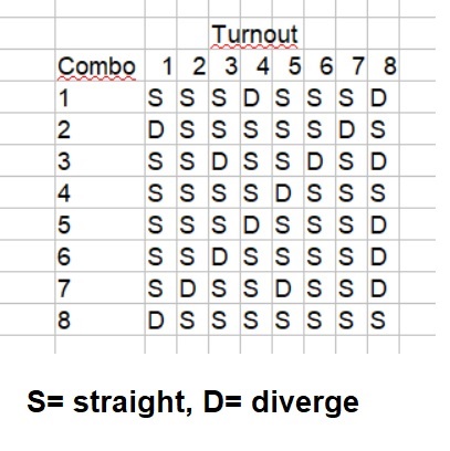
So you fill in a basic table showing the desired turnout positions for each of your 8 combinations.  Here's an obviously incorrect example but illustrates the concept:

rotary switch define matrix

For each of your 8 combinations, you specify what the position of the 8 turnouts (straight or diverge).

In this case, the "matrix" is 8 x 8 so you specify 64 positions.  Then you count up the "D"s which happens to be 16 in this case.  If I took the time to understand your yard configuration I could fill in the matrix for you but then I'd be doing all your work!

For each "D" you will need 1 diode.  So in my arbitrary example, you need 16 diodes.

Virtually any diode will work and are cheap - a penny or two a piece.  "We" can provide the exact wiring diagram once you define the matrix.  So you have a multi-position rotary switch, a diode matrix, your 8 gang relay board, and a 12V DC wall-wart (assuming your relay board is 12V DC).

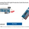
Actually what I think is more interesting is if you can find an economical 8-position rotary switch.  The switch is carrying minimal current (much less than 1 Amp).  But I notice for less than $2 shipped, you can get a 12-position rotary switch on eBay with knob!

rotary switch 12 position

In other words, you'd only use 8 positions of the 12.  Or, you could expand the matrix by 2 combos where combo #9 forces ALL turnouts to Straight...and combo #10 forces ALL turnouts to Diverge.  This would be just "for fun" to force all turnouts one way or the other as a contrived test mode.  This would "cost" you 8 additional diodes or about a dime!  Are we having fun yet!?

Attachments

Images (2)
  • rotary switch define matrix
  • rotary switch 12 position
Last edited by stan2004

Thanks guys !!!  I was considering a diode matrix and had started the truth table but was way laid by the thought of building a breadboard matrix.  I had delusions of grandeur of some type of encoder offering an all in one solution.  Now, thanks to you fine folks I'm back on the diode matrix.   I found this application primmer on-line for using a diode matrix to automate yard turnout control.   https://www.thehobbyshed.club/diode-matrix

Here is another article I found on the same diode matrix yard automation subject: http://www.circuitous.ca/StallMatrix.html

Also, I was delighted to learn, kits are available with a PCB to construct the matrix.

The Hobby Shed website offers an interesting array electrical/electronic "How To" articles for model railroaders.  https://www.thehobbyshed.club/how-to

This is turning out to be a fun project.

BTW, are you using coil switch-machines and if so did you note the comment in your first link about using a CDU?

You mentioned the DCS Route function.  As you know, the DCS AIU(s) go one by one thru the various turnouts to set up a Route.  So you hear click, click, click, repeated up to the number of turnouts under DCS control.  That is, if using coil switch machines which draw short bursts of current easily over Amp, you can overload your power supply if simultaneously driving multiple coils.  Hence the DCS Route function steps thru each turnout generating 1/2 second pulses so it can take many seconds to set up a route.

In the "fun" category, I was pondering how to perform this type of sequencing without a CDU and, to your point, without programming (such as with an Arduino or similar microcontroller).  So OGR being a discussion forum, I recalled the low-cost LED light chaser-sequencer kit that I believe was discussed on OGR as a way to build an inexpensive LED traffic light controller.

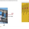
led light chaser kit for about a buck

The 10 LEDs on this board turn on one at a time in sequence.  So what if this timing could be paired with the diode matrix so that the 8 turnouts are activated in sequence rather than all at once.  In other words, if the 8 gang relay module is used, you would hear only 1 relay at a time change position rather than (up to) all 8 relays changing at once which would likely overwhelm the power supply for coil-type switch machines.

Ironically, when using this module as a cheap LED red-yellow-green traffic light controller, it too would use a diode-matrix!

Attachments

Images (1)
  • led light chaser kit for about a buck

It's true what they say about a little knowledge is dangerous.  So I have a rotary switch controlling turnouts through a diode matrix.  That works.  But I don't want the all the turnouts flipping or yard tracks powering up when I spin the rotary switch.   An orderly turn-on would be nice.  So maybe a momentary  pushbutton enable switch to set the turnouts after the rotary switch position is set ?  Then, I wouldn't want the train moving before the turnouts are set.  So maybe another momentary pushbutton to enable track power based on rotary switch position ?

Now the DZ1000 and track power are AC.  DZ1000 powered off fixed 14 VAC.  Tracks powered through single TIU channel.  Same channel as powering the loop feeding the yard.  So, going to need one bank of relays feeding the DZ1000s and another controlling track power ?

The next question is what happens after the pushbuttons are released or the layout power is turned off.  I would want the turnout states and yard power states to remain unaltered unless commanded by the operator abet the auto non-derailing feature.  Yard track relay will change state and turn off yard track power when the track power relay button is released.  Same with the DZ1000 relays.  Seems like latching relays are needed ?   Do those China relay banks come in the latching variety ?

@stan2004 posted:

BTW, are you using coil switch-machines and if so did you note the comment in your first link about using a CDU?

You mentioned the DCS Route function.  As you know, the DCS AIU(s) go one by one thru the various turnouts to set up a Route.  So you hear click, click, click, repeated up to the number of turnouts under DCS control.  That is, if using coil switch machines which draw short bursts of current easily over Amp, you can overload your power supply if simultaneously driving multiple coils.  Hence the DCS Route function steps thru each turnout generating 1/2 second pulses so it can take many seconds to set up a route.

In the "fun" category, I was pondering how to perform this type of sequencing without a CDU and, to your point, without programming (such as with an Arduino or similar microcontroller).  So OGR being a discussion forum, I recalled the low-cost LED light chaser-sequencer kit that I believe was discussed on OGR as a way to build an inexpensive LED traffic light controller.

led light chaser kit for about a buck

The 10 LEDs on this board turn on one at a time in sequence.  So what if this timing could be paired with the diode matrix so that the 8 turnouts are activated in sequence rather than all at once.  In other words, if the 8 gang relay module is used, you would hear only 1 relay at a time change position rather than (up to) all 8 relays changing at once which would likely overwhelm the power supply for coil-type switch machines.

Ironically, when using this module as a cheap LED red-yellow-green traffic light controller, it too would use a diode-matrix!

Stan, you are always amazing !!   The Yard turnouts are DZ1000 which I believe don't present much of a simultaneous current load or spike.  Although rotary switch contact current rating is a consideration, hence the need for relays I believe.  I don't have a lot of space in the control panel for a larger more robust switch.  I have a lot of NJ switch machines on other routes.  I have larger size stepdown transformers feeding the turnouts although CDU might still be a consideration for the NJ type in simultaneous operation.  I did overload at least one of the transformers illuminating all the incandescent lamps on the old fashion lever turnout controllers.  Switching to LEDs eliminated the overload.

I think we need to divide and conquer.

Issue 1. Track power control.  I did not give this any consideration.  So do you have some mechanism that detects a turnout's position (e.g., monitoring the LED indicator of the turnout itself) which then controls (e.g., via a relay) track power to a newly powered siding connected into the mainline?

Issue 2. The DCS Watchdog.  If your entire yard is connected to a single TIU channel, are you familiar with the so called watchdog issue?  In other words, when powering up a new block/siding from a TIU channel that has already been on for a while, the TIU does NOT generate the watchdog signal which keeps a newly powered DCS engine silent and in command-mode.  There are workarounds including the so-called DCS PBW (Perpetual Barking Watchdog) developed right here on OGR!

Issue 3. Turnout position between sessions.  If using the inexpensive relay modules, these are definitely the NON-latching type.  When you turn power off to the module, the relays turn OFF.  When you turn power back on, IF you are using the rotary-switch with diode-matrix, then the relays would immediately set themselves to the rotary-switch selection.  So you would hear a simultaneous "click" in unison of any relays that are to be set per the diode-matrix.

Yes, there are latching relay modules but they are quite spendy.  I occasionally look for inexpensive off-the-shelf latching relay modules as this would be useful for hooking up a DCS-AIU switch port to Tortoise type switch machines.  So far, no luck.  I found this photo I must have posted on OGR about latching relay options:
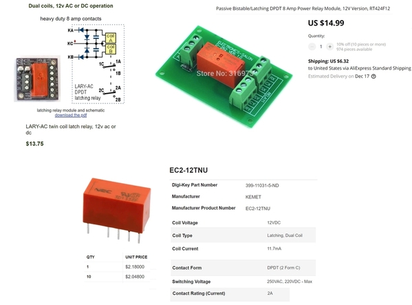
latching 12V DPDT dual-coil relay options

I just checked on eBay and you don't save much by going to a 2 or 4 channel latching relay module:

12v latching relay ebay 8 Amp

Now in your situation, since the DZ1000 switch machines are apparently relatively low power, you don't need an 8 Amp relay and you also don't need Dual Pole (DPDT) relays but that's somewhat moot if that's all that's out there!

So if the objective is to retain turnout position between operating sessions, and you choose latching relays as the "memory" mechanism, I'd suggest hand-wiring and soldering in the $2 latching relay.  IIRC the pins are on a 0.1" grid so would drop in to the perforated prototype board used for the diode matrix.

BTW. If searching eBay for latching relays, you will find many listings that use the term "latching" or "bistable".  But these relays revert to the "off" state when power is turned off to the module.  Buyer beware.

BTW #2.  Now this is getting fairly deep down the rabbit hole.  But there are complications when using typical latching relays with a diode-matrix as proposed.  I don't know the simplest way to explain it, but with non-latching relays or with the diode-matrix directly driving switch machines (as shown in the linked diagram), you only need to tell the relay or switch-machine when to turn ON (when to Diverge).  A latching relay must separately be instructed to turn OFF (when to Straight).  In other words, you tell a NON-latching relay to either DIVERGE or NOT DIVERGE.  You tell a LATCHING relay to either DIVERGE or STRAIGHT.  Seems like semantics but can have consequences in regards to the basic diode-matrix method.

Issue 4.  Rotary switch side-effect.

To your point, if panel space makes it impractical to install 8 individual switches then you must deal with what happens when you rotate thru intermediate positions, say from #1 to #8.  That is, as you go from #1-to-#2 the relays will instantly change to the #2 turnout pattern.  And so on until you get to position #8.  I guess you could turn the knob really quickly to hide the chattering relays!

But in the rotary-switch's "defense" note that it provides the memory to effect what amounts to latching relay behavior!  It is true that when you first power up the rotary-switch, diode-matrix, and NON-latching relay module it will take a fraction of the second for the 8 relays to go to their intended positions.  But this happens in a blink of an eye.  This needs confirmation but when a DZ1000 loses power, doesn't it maintain its position?

But getting back to the undesirable chatter of clicking relays attempting to track the rotary switch as it passes by intermediate positions.  I realize you've proposed some kind of "go" button that you press after you've set the rotary switch.  But in the spirit of OGR being a discussion forum, I think we can do better!  I can imagine methods but while not expensive (a couple bucks in parts) nothing simple that doesn't require soldering. This one has me stumped just now; I also think any solution might be tied into the track power control Issue above.  In other words, I'd like to hear more about how you want track power timed/controlled relative to turnouts changing position.

I'll now quit my rambling

Attachments

Images (2)
  • latching 12V DPDT dual-coil relay options
  • 12v latching relay ebay 8 Amp
Last edited by stan2004
@Junior posted:

This thread caught my interest. And as I started reading it and got to the discussion about a "diode matrix", I thought "OMG this is a "decision table"!" I used to use them writing COBOL programs (way back when)!

What goes around comes around...or I suppose never left in the first place!  Perhaps self-serving, but according to Cobol Cowboys :

-COBOL supports close to 90% of Fortune 500 business systems today.

-COBOL is 65% of active code used today; and runs 85% of all business transactions.

-200 billion lines of COBOL code are still in use today by various industries, according to IBM.

Note this is business software (COBOL = Common Business Oriented Language), not the software in your smartphone, laptop, TV, car, or...wait for it...model train

Oh my God!  I used to write COBOL code back in another life!

On to the OP’s question...why a rotary switch? Just put a single, momentary contact push button on each track in your diagram and use that instead of the rotary switch. You don’t want continuous contact in this application anyway. You want a momentary contact to throw the switches involved.

@Junior posted:

This thread caught my interest. And as I started reading it and got to the discussion about a "diode matrix", I thought "OMG this is a "decision table"!" I used to use them writing COBOL programs (way back when)!

I just love this forum....you never know what you're gonna learn next!

You must be a youngster, I was doing FORTRAN in the good old days.  And then there are those Karnaugh Maps.

I told you I was dangerous.   So, it will take me a while to sort this all out.  At least for now, I am familiar with the Azatrak LARY-AC latching relays, $13.75.  They work on 12 V AC or DC.  They mechanically latch, so no changing state when power is off.  I use these on my layout already.  The blocking and protecting diodes are surface mount.  I've fried a couple but easily fixed with jumper diodes.  The best part is the Azatrak owner is extremely helpful, just like yourself.

I've always found the diode matrix interesting and also been wanting to add capacitor discharge circuitry to my Atlas twin coil switch machines. The Hobbyshed site looks interesting, nice link! The www.circuitous.ca site is also a good one and has more model train related circuits to go along with the CDU circuit!  The time may have come to follow along here and give this a try myself.

@Rich Melvin posted:

Oh my God!  I used to write COBOL code back in another life!

On to the OP’s question...why a rotary switch? Just put a single, momentary contact push button on each track in your diagram and use that instead of the rotary switch. You don’t want continuous contact in this application anyway. You want a momentary contact to throw the switches involved.

Hi Rich,

Thanks for your thoughts !!  The rotary switch is a lack of control panel real estate solution.  It's also intended to make sure I'm not firing up more than one lane at a time in my yard.  I will not be able to see the yard since it is in another room.  Considering a remote camera.

And yes, I agree, the DZ1000 wants momentary contact.  I was thinking I would use the diode matrix to control relays and the relays control to control DZ1000.  The relays would have to be latching.  There would be one momentary switch to feed all the relay common contacts.  Only the DZ1000s selected by the diode matrix would flip.  The others would be energized but would remain in place.

Stan - Rotary Switch Side Effect,  I'm thinking the easiest way to eliminate the unwanted relay and/or DZ1000 state changes when selecting rotary switch positions is to add an automation on/off switch.  The switch would control primary 12 VDC, 14 VAC and track power to the automation electronics.  The sequence would be to shut automation power  off before changing rotary switch position.  Not ideal but it will work.  Upon power up, the latching relays will spring to their newly selected positions.  When I push the momentary switch, the diode matrix selected turnouts will flip to their new positions.  A second momentary track power button will close a non-mechanical latching relay which provides track power to the yard selected track.  The automation on/off process or layout shutdown will unlatch the non-mechanical relay and ensure no surprises upon power up.

I'm not sure I mentioned that the yard is in another room and I can't actually see it. I'm considering a remote camera.

@rtr12 posted:

I've always found the diode matrix interesting and also been wanting to add capacitor discharge circuitry to my Atlas twin coil switch machines. The Hobbyshed site looks interesting, nice link! The www.circuitous.ca site is also a good one and has more model train related circuits to go along with the CDU circuit!  The time may have come to follow along here and give this a try myself.

Thanks for the Circuitous link.  Turns out I had already bookmarked their Diode Matrix tutorial but failed to realize there is a whole lot more !!   I like the visuals of their tutorial since it make one realize the Diode Matrix is basically a bunch of diode OR circuits.

It seems we're changing tack here going to a momentary activation configuration.  I'm not familiar with the DZ1000 operation so a few questions.

dz1000 schematic

1a. Do you intend to install the Remote (with its 2 buttons and 2 LEDs)...perhaps to give manual local control for testing/troubleshooting?

1b. Does the LED "trickle" current in the Remote (in addition to indicating position) perform any kind of "holding current" to keep the switch machine securely in its intended S or D position?  For example, my understanding is the Tortoise switch machine motor is stalled with a holding current to keep it securely in its intended position.

2. How quickly does it change positions?  If going to a momentary model you'd obviously have to apply power for some finite duration.  For example, a 1/2 second relay closure is what the DCS-AIU provides on its SWitch port outputs.

Regarding the issue of Latching relays.  If going to the momentary activation model using a manually activated push-button, and if the DZ1000 remembers its position when unpowered, then I don't see why you need latching relays for the turnouts.  Previously, with the NON-latching gang relay module, it was always supplying S or D "power" to the turnout and hence had to have memory since interrupting power "resets" the relays.

Also, I still don't understand how and when power is applied to each block.  Is it a simple one-to-one correspondence between the 8-position rotary switch and which of the 8 blocks is powered?  In other words, can you "tap into" the diode matrix and (using the momentary model) identify a momentary pulse that corresponds to turning on (latching on) a particular block?  As mentioned earlier, a latching relay requires a separate trigger to turn OFF.

Addendum.  As you most recently proposed for TRACK POWER control, I see that removing power to a non-mechanical latching relay can be a proxy for a turn OFF trigger.

non mechanical latching relay 12V DC

Curious if you've found a suitable multi-channel non-mechanical latching relay module?  I've used the above 1-channel 12V DC non-mechanical latching relay module.  There's a 2-pin connector meant to go to a momentary push-button.  Press button, it turns ON.  Press it again, it turns OFF. And alternates thereafter.  When power is removed the relay turns OFF.  I think you might find similar widgets called "bi-stable" or "toggle mode" relays.

Getting into the details a bit, but for the relay module shown, you must provide a "low" trigger which in effect is DC- voltage.  The diode matrix example in your link illustrates a "high" trigger logic where the DC+ feeds thru the matrix to be applied to the turnout.  This is one of those dot the i's and cross the t's.  That is, you can reverse the diodes in the matrix so it generates a DC- trigger if you are sharing the matrix logic between firing the turnout and enabling track power.  Most multi-channel relay modules let you select LOW or HIGH trigger voltage.

Attachments

Images (2)
  • dz1000 schematic
  • non mechanical latching relay 12V DC
Last edited by stan2004
@stan2004 posted:

It seems we're changing tack here going to a momentary activation configuration.  I'm not familiar with the DZ1000 operation so a few questions.

dz1000 schematic

1a. Do you intend to install the Remote (with its 2 buttons and 2 LEDs)...perhaps to give manual local control for testing/troubleshooting?

1b. Does the LED "trickle" current in the Remote (in addition to indicating position) perform any kind of "holding current" to keep the switch machine securely in its intended S or D position?  For example, my understanding is the Tortoise switch machine motor is stalled with a holding current to keep it securely in its intended position.

2. How quickly does it change positions?  If going to a momentary model you'd obviously have to apply power for some finite duration.  For example, a 1/2 second relay closure is what the DCS-AIU provides on its SWitch port outputs.

Regarding the issue of Latching relays.  If going to the momentary activation model using a manually activated push-button, and if the DZ1000 remembers its position when unpowered, then I don't see why you need latching relays for the turnouts.  Previously, with the NON-latching gang relay module, it was always supplying S or D "power" to the turnout and hence had to have memory since interrupting power "resets" the relays.

Also, I still don't understand how and when power is applied to each block.  Is it a simple one-to-one correspondence between the 8-position rotary switch and which of the 8 blocks is powered?  In other words, can you "tap into" the diode matrix and (using the momentary model) identify a momentary pulse that corresponds to turning on (latching on) a particular block?  As mentioned earlier, a latching relay requires a separate trigger to turn OFF.

Addendum.  As you most recently proposed for TRACK POWER control, I see that removing power to a non-mechanical latching relay can be a proxy for a turn OFF trigger.

non mechanical latching relay 12V DC

Curious if you've found a suitable multi-channel non-mechanical latching relay module?  I've used the above 1-channel 12V DC non-latching relay module.  There's a 2-pin connector meant to go to a momentary push-button.  Press button, it turns ON.  Press it again, it turns OFF. And alternates thereafter.  When power is removed the relay turns OFF.  I think you might find similar widgets called "bi-stable" or "toggle mode" relays.

Getting into the details a bit, but for the relay module shown, you must provide a "low" trigger which in effect is DC- voltage.  The diode matrix example in your link illustrates a "high" trigger logic where the DC+ feeds thru the matrix to be applied to the turnout.  This is one of those dot the i's and cross the t's.  That is, you can reverse the diodes in the matrix so it generates a DC- trigger if you are sharing the matrix logic between firing the turnout and enabling track power.  Most multi-channel relay modules let you select LOW or HIGH trigger voltage.

1a)  yes I plan to install the 2 button controller with LED as an alternate in addition to the diode matrix.  The controller attaches at the latching relay contacts.  The turnout changes state in response to the diode matrix momentary push button OR the DZ1000 controller momentary buttons.  Not sure if isolation is needed here to prevent back flow ?

1b)  No, the trickle just illuminates the LEDs.  This circuit doesn't always play nicely with others.  For example, it doesn't like MTH Dwarf Signals.    Can't use a common isolated rail to trigger both the turnout and the signal.

2) Snap action, instantaneous  It's not slow motion like tortoise.

Latching Relays  - The Diode Matrix works on DC and the DZ1000 works on AC.   The DZ1000 also need the positive and negative portions of the sine wave to operate. The relays provide the interface.  The latching relays handle the power interrupts.  However, the turnouts do have memory and you do have a point.  Maybe I need to think more here.

Block Power -- Tap of rotary switch position to a DC non-mechanical (bi-stable) latching relay.  Use momentary switch to turn block ON and  latch.  Upon power loss, the block power will restart (reset) in the OFF position (your proxy).  The relay also provides the DC/AC interface.

Plan uses to momentary push button switches:  one to set the turnout position, the other to turn on block power.  i.e. train doesn't move until switches are set.

Triggers  - You're correct, the shown diode matrix provide + DC trigger.  If I use the LARY-DC latching relay, it uses either positive or negative DC triggers.

Also, my AC and DC ground/neutral are not common.

Stan, I'm not sure if you realize it, but you are being a BIG help.  It's making me think and hopefully uncover the pitfalls of my plan.  Thanks.  Keep telling me where the issue are.

As an aside, I don't have enough real estate on my control panel for all the DZ1000 controllers.  I'm one space short.  My plan is run the two reversing loop turnouts in parallel.  One controller for two turnouts.   Dennis the owner of ZStuff, says no problem as long as I keep wiring straight to straight and diverge to diverge.

I think (hope) I've absorbed your comments.  Here's my latest concoction:

shorling yard dartboard 2

This uses ONLY NON-latching gang relay modules...in this case the 8-channel 12V DC version which can be found for the insanely reasonable cost of about $1/relay.

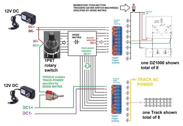
This builds on your general concept of separating turnout control from track power control.  It "works" as follows; in no particular order:

- One rotary switch, 1 Pole, 8 throw.

- TWO (2) 12V DC wall-warts.  These are a few bucks a piece.  Important that there be two DC adapters.  One provides 12V DC+/DC- for relay turnout control.  The other (electrically isolated)  provides 12V DC1+/DC1- for relay track power control.  This is kind of head-scratching but is explained below.

- The diode matrix is whatever it needs to be.  The "trick" is the same diode matrix is simultaneously generating the "truth table" for the turnout selection and the track power selection.  This possibly head-exploding concept works because of the two separate/independent 12V DC wall warts.  Neither wall-wart is "aware" of the other's existence.  This method does NOT constrain the turnout selection to exactly match the track power selection.  It may well be that there is a one-to-one correspondence between turnout and track power but this is not a requirement.

- The 8-channel TURNOUT relay module is non-latching.  As long as system power is on, the relays are set accordingly.  The key is the commons of the 8 relays are fed by a single momentary Push-button to 14V AC Accessory common (turnout AC common).  So when you push the button, all 8 DZ1000 turnouts get a momentary command to the Straight or Diverge as specified by the diode matrix.  Again, the diode matrix continuously provides the DC+ selection to all 8 DZ1000s.  But of course nothing happens until the pushbutton is activated.

- The 8-channel TRACK POWER relay module is non-latching.  In this case, there is a ON/OFF toggle (NOT momentary).  If the toggle is OFF, the diode matrix sends nothing to the relay module.  All tracks are unpowered.  If the toggle is ON, the diode matrix sends DC1+ to whichever relays the diode matrix specifies (can be more than 1 track).

- So in practice.  When changing rotary position, first turn the toggle switch OFF.  All TRACK POWER relays turn OFF.  All tracks are unpowered.  Then set the rotary as desired.  Then momentarily press the TURNOUT pushbutton.  This sets all the turnouts per the diode matrix.  Then turn the toggle switch ON.  TRACK POWER is now applied to the appropriate tracks per the diode matrix.

- When system power is lost, all relays turn OFF whichever state they were in.  Track Power is removed from all tracks.  The DZ1000's retain their position whatever they were.

- When system power is restored, the DZ1000's will be at their previous positions from their own mechanical memory.  Nothing happens with the turnouts until the pushbutton is pressed so all's well there.  IF the toggle switch is OFF when system power is restored, there is no track power to any block.  If the toggle switch is ON when system power is restored, the track(s) specified by the diode-matrix will go on.

- I do not think a special power-on pulse needs to be generated.  Yes, I suppose you could change the rotary switch position when system power is OFF.  In this case the rotary switch would not match the mechanical memory of the DZ1000s.  If this is really an issue, then of course a simple circuit could be added to provide this one-time startup pulse.

- This method uses two switches (one toggle, one pushbutton) and two 12V DC adapters.  What is given-up if you only use one switch and/or one 12V adapter.  Or, how much additional circuitry/hassle would eliminates one or both switches and/or one of the DC adapters.  Those are questions for another day.

This is a strawman starting point to see if we're even on the same page!

Attachments

Images (1)
  • shorling yard dartboard 2
Last edited by stan2004
@Rich Melvin posted:

You are over-complicating this. If you use the diode matrix solution, you don’t need any relays, latching or otherwise. You just need a capacitive-discharge power supply to power the switches. Set the rotary switch, push a button to energize the chosen path through the matrix, throw the switches, and done.

The diode matrix "solution" as described in the links can only provide "positive" or "negative" (choose one) control signals depending on which way the diodes are oriented in the matrix.  In techno-speak what the DZ1000 instructions call the "COMMON" signal has to be able to source or sink current.  I suppose there are exotic variants but garden-variety CD circuits use capacitors which are DC devices and provide bursts of current in one polarity.

Additionally, part of Shorling's application is to control TRACK POWER.  Again, as a diode matrix uses, umm, diodes it can only provide DC signals so some device (relay, triac, whatever) is needed to switch AC voltages per the diode matrix.  Additionally, irrespective of whether the track power is AC or DC, it would be bulky and expensive to use 3A, 5A, 10A or whatever high-power diodes when constructing a diode-matrix which might have dozens of diodes.  More practical to use inexpensive low-current diodes in the matrix and buffer the output with a relay or whatever to switch track power currents.

GRJ & Gilly -  I do realize that I can use either my DCS or Legacy systems to program routes.  However, this automation is for a yard not yet built to be located in another room in my basement on the floor.   Well, almost on the floor.  The layout and yard basement floors are on different elevations.  The plan is to build a tray.  In the summer I run a dehumidifier but will that be adequate especially if I put a cover on the tray to keep the yard clean.  A tray fan may help.  Block track power control is also a consideration.  In any case, there is some greater degree of control required due to the lack of visuals, not to mention the Grandkids.  A visual aide like a camera is necessary. The plan is to minimize the wire runs by keeping the electronics close to the yard.  It's 25-30 feet from the layout control panel to the yard.  Access to address derailments, etc is a PITA.

@stan2004 posted:

I think (hope) I've absorbed your comments.  Here's my latest concoction:

shorling yard dartboard 2

This uses ONLY NON-latching gang relay modules...in this case the 8-channel 12V DC version which can be found for the insanely reasonable cost of about $1/relay.

This builds on your general concept of separating turnout control from track power control.  It "works" as follows; in no particular order:

- One rotary switch, 1 Pole, 8 throw.

- TWO (2) 12V DC wall-warts.  These are a few bucks a piece.  Important that there be two DC adapters.  One provides 12V DC+/DC- for relay turnout control.  The other (electrically isolated)  provides 12V DC1+/DC1- for relay track power control.  This is kind of head-scratching but is explained below.

- The diode matrix is whatever it needs to be.  The "trick" is the same diode matrix is simultaneously generating the "truth table" for the turnout selection and the track power selection.  This possibly head-exploding concept works because of the two separate/independent 12V DC wall warts.  Neither wall-wart is "aware" of the other's existence.  This method does NOT constrain the turnout selection to exactly match the track power selection.  It may well be that there is a one-to-one correspondence between turnout and track power but this is not a requirement.

- The 8-channel TURNOUT relay module is non-latching.  As long as system power is on, the relays are set accordingly.  The key is the commons of the 8 relays are fed by a single momentary Push-button to 14V AC Accessory common (turnout AC common).  So when you push the button, all 8 DZ1000 turnouts get a momentary command to the Straight or Diverge as specified by the diode matrix.  Again, the diode matrix continuously provides the DC+ selection to all 8 DZ1000s.  But of course nothing happens until the pushbutton is activated.

- The 8-channel TRACK POWER relay module is non-latching.  In this case, there is a ON/OFF toggle (NOT momentary).  If the toggle is OFF, the diode matrix sends nothing to the relay module.  All tracks are unpowered.  If the toggle is ON, the diode matrix sends DC1+ to whichever relays the diode matrix specifies (can be more than 1 track).

- So in practice.  When changing rotary position, first turn the toggle switch OFF.  All TRACK POWER relays turn OFF.  All tracks are unpowered.  Then set the rotary as desired.  Then momentarily press the TURNOUT pushbutton.  This sets all the turnouts per the diode matrix.  Then turn the toggle switch ON.  TRACK POWER is now applied to the appropriate tracks per the diode matrix.

- When system power is lost, all relays turn OFF whichever state they were in.  Track Power is removed from all tracks.  The DZ1000's retain their position whatever they were.

- When system power is restored, the DZ1000's will be at their previous positions from their own mechanical memory.  Nothing happens with the turnouts until the pushbutton is pressed so all's well there.  IF the toggle switch is OFF when system power is restored, there is no track power to any block.  If the toggle switch is ON when system power is restored, the track(s) specified by the diode-matrix will go on.

- I do not think a special power-on pulse needs to be generated.  Yes, I suppose you could change the rotary switch position when system power is OFF.  In this case the rotary switch would not match the mechanical memory of the DZ1000s.  If this is really an issue, then of course a simple circuit could be added to provide this one-time startup pulse.

- This method uses two switches (one toggle, one pushbutton) and two 12V DC adapters.  What is given-up if you only use one switch and/or one 12V adapter.  Or, how much additional circuitry/hassle would eliminates one or both switches and/or one of the DC adapters.  Those are questions for another day.

This is a strawman starting point to see if we're even on the same pageI!

Thanks again Stan,  I'm thinking of a simpler solution for the Block Track Power.  Select each relay directly from the Rotary switch.  A momentary would prevent applying unwanted block power as the rotary switch is positioned and the toggle is ON.  Plus I already have a large  (33 amp) 12 VDC supply.   Do they make the relay bank in DPDT.  I can use the second pole to create a resettable latch. I could also use 8 individual China relay modules if DPDT.  The China "Bi Stable" latching relays will also work.  Grandkids rotating the switch is also needs a Murphy Proof.

Good point on Rotary switch position and actual yard state.  I've been thinking about that.  The camera will allow parking without slamming the bumper.  A bumper light will indicate block power status.  I was going to rely on the DZ1000 Controller LED for actual turnout position but that's a lot of wire ?

I am not aware of inexpensive multi-channel 12V DC DPDT relay modules.  Earlier I showed various multi-channel LATCHING DPDT relay modules but are around 10 times the price per relay as the non-latching SPDT type.  If I were going to "make" a non-mechanical latching relay using a double-pole relay, I'd simply co-opt 2 adjacent SPDT relays on a low-cost multi-channel relay module; so, for example, "make" a DIY 4-channel non-mechanical latching relay module out of your 8-channel non-latching module.

Understood on your monster 12V 33A power supply.  But I hasten to point out a 12V DC wall-wart only costs a couple bucks.  The purpose of the 2nd DC supply in your application is because it is electrically isolated which can be used to advantage; the 2nd DC supply is not because of the lack of power from one.  This is sort of similar to how isolated-rail triggering works in O-gauge.  But I digress.

So here's another variant that uses only a single 12V DC power supply.  I will address the rotary switch issue later and this configuration will be useful as a starting point.

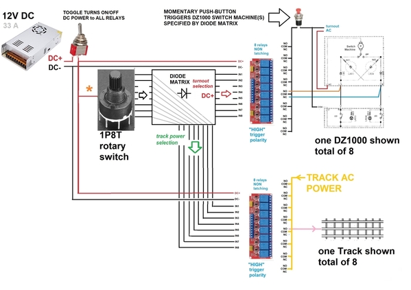
shorling yard dartboard 3

So, again, this uses ONLY non-latching relays.  There is only one (1) 12V DC power source.  The diode matrix is shown with direct connections from the 1P8T rotary switch output to 8 inputs for the track power relays.  So all 2 x 8 = 16 relays are always "live" following the rotary switch.  Of course the turnout relays will be not have any effect on the actual turnouts until the turnout pushbutton is pressed.

But for a disciplined user, I think this might be the simplest configuration.  So when you want to change yard position, you first turn OFF the toggle switch.  All relay power is lost so all relays turn OFF.  Nothing happens to the turnouts themselves and they remain where they were.  All track power is lost.  Then you set the rotary switch to the new position.  Then you turn ON the toggle switch.  All the relays go to the new pattern.  The new track block turns ON.  Then you press the push-button and the turnouts reconfigure to the new pattern.

So I get now that it is very important (grandkids fiddling) that the rotary switch do NOTHING until/unless you press the momentary button.  My first response was, but what if the kids fiddle with the DZ1000 controller(s) pressing the direction button(s) willy-nilly because it's cool to see the red and green LEDs change?   Anyway, just had to throw that in.

Back to above diagram.  When the toggle switch is ON, an un-disciplined user fiddling with the rotary switch will cause track power to jump around.  Note the orange asterisk * next to the rotary switch.  Insert a momentary push-button...AND change all 16 non-latching relays to non-mechanical latching relays.  Now, fiddling with the rotary switch has no effect.  To change yard position, turn off toggle; all relays turn OFF which resets any latched relay (since they are non-mechanical).  Set rotary as desired.  Turn toggle ON; nothing happens yet.  Then press the new asterisk push-button; the turnout and track power relays are latched per diode matrix.  Track power comes on to whichever track.  Then press the momentary turn-out button; the turnouts are set to the correct pattern.

Attachments

Images (1)
  • shorling yard dartboard 3
@shorling posted:

...

A bumper light will indicate block power status.  I was going to rely on the DZ1000 Controller LED for actual turnout position but that's a lot of wire ?

So bumper lights are viewed with your camera?  Where do the Controllers reside?  Can you really get enough resolution with your camera and screen size to see your entire yard and the bumper lights and the tiny red/green Controller LEDs?   Or by a "lot of wire" you mean to run the LEDs 30 feet or whatever to the control panel in the other room?

OGR being a discussion forum, here's yet another version of, To Latch or Not to Latch, that is the question.

I can't get past the cost penalty of latching relays...whether "true" latching or "fake" non-mechanical latching!

shorling yard dartboard 4

Apparently you will be soldering a bunch of diodes to make the diode-matrix...likely using a perforated prototyping board.  You can get a digital IC chip that is, of all things, called a Latch!  An 8-bit version is maybe 50 cents.  The "output" of your rotary switch is 8 lines which are binary (low or high, 0 or 1, etc.).  An 8-line digital latch (aka register, flip-flop) transfers the value of its 8 inputs to its 8 outputs upon command (when receiving a clock pulse) and then maintains that output value until the next clock pulse.  So let's say we can generate a one-time clock pulse when power is initially applied to the system.  The 8 lines from the rotary switch are now captured forever (until power is removed) and will not change even if the rotary switch changes.  These 8 latch outputs now drive the diode-matrix for turnout selection and track block power control.  No need for latching relays!

To be certain, there are i's to dot and t's to cross.

Attachments

Images (1)
  • shorling yard dartboard 4

As I ponder the techno stuff, I thought I would elaborate on my Grandkid's "fiddling".   The Grandkid's are keenly aware that it would not please Grandpa to "push buttons" unless Grandpa says so.  They enjoy running a train with their remote, blowing the horn, operating the milk car, etc.  However, they do believe that they are quick studies and are observant about layout operation.  So, when the adults are otherwise occupied, a Grandchild, particularly boys, might wonder off and try their hand at layout operation.  This is especially true with items new to the layout.

@stan2004 posted:

So bumper lights are viewed with your camera?  Where do the Controllers reside?  Can you really get enough resolution with your camera and screen size to see your entire yard and the bumper lights and the tiny red/green Controller LEDs?   Or by a "lot of wire" you mean to run the LEDs 30 feet or whatever to the control panel in the other room?

The yard is just for train storage.  I don't have any interest in having a prototypical operational yard.  The camera's primary purpose would be to guide the train to a safe stop before it crashed into the bumper.  Also, it would be handy to verify that the train is actually exiting the yard upon command.  The train might not be moving because of: DCS issue, no track power, dirty track, etc.

I'm not thinking of a train mounted camera.  It would be an IP, Wifi or direct connect camera which have excellent resolution.  Field of view might be a concern.    I have a small TV that I use as a monitor mounted over the layout.

I do have FM engine which I installed ERR TMCC and a camera.  The camera has terrible video.    I also have a couple of Lionel camera equipped cars which I have yet to take out of the box.  Projects for another day.

I may be rethinking using the DZ1000 controllers.  The controllers do provide feedback of actual turnout position.  So, there is a trade here.  Knowing the turnout positions would be nice.  Having a second way to control individual turnouts is a nice to have.  However, there are only 6 spaces left on the control panel for DZ1000 controllers.  Maybe these 6 spaces would be better used for future expansion.

The wire route distance between the layout control panel and the room where the yard will be located is approximately 25 feet.  6 controllers x 3 wires each x 25 feet is a bunch of wire.  Also, I don't know if the DZ1000 is dependent on the LED trickle.  The DZ1000 may use stall motors.

Not sure if we're sync'd on which version is under discussion.  In case not obvious, I'm no fan of using any type of latching relay in this application. 

Anyway, if referring to the "asterisk" version where you momentarily press a button to latch the chosen (1 of 8) track power relays...you'd also need latch the desired turnout configuration from the diode matrix.  Yes, the turnouts themselves will not change until you press the turnout momentary button.  But if the turnout relays were non-latching, they would all be OFF after you release the asterisk push-button.  I suppose you use a double-pole momentary push-button to activate the turnout; one pole would momentarily power up the diode-matrix (like the asterisk push-button) and the other pole would apply AC ground to the commons of the turnout relays.

If you were referring to other variants, I understand nothing happens to the actual turnouts until the push-button is pressed...but I can see a case to be made that the rotary switch should have zero effect period until some push-button is pressed saying "go,"  Chattering relays (even if they do not change the turnouts themselves) is arguably not zero effect...even if the relays are clicking 30 feet away sight unseen!  If a tree falls in a forest and nobody's around to hear it,  etc. etc.

Not sure what you mean by the track block transients at t=0+.

Stan -  Referring back to the strawman with 12 VDC 33 amp supply.  This seems closest to what I'm thinking, however it does not set the turnouts before applying block track power.  If a third push button is added to the track relays bank similar to the turnout bank than no turnouts flip and no block track powers until the operator chooses.    If the relays are non-mechanical latching, the block track power will be OFF after a power interrupt.

Operation is as follows:  Set the rotary switch to desired position, turn on the toggle, turnout and block track power relays move to position, press the turnout momentary, turnouts flip and remain upon release, press the block track power momentary, selected block turns ON latched and remains ON upon release.  If the rotary switch is moved, relays chatter but train operation is unaffected.  During power interrupts, turnouts do not change state and the block track power is OFF.

T=0+ refers to the instant in time immediately after applying power.  There is always a transient response but it can be orderly or don't care ?  In the strawman's where power is applied to the selected block track upon automation power up, my thought is: does any of the transient actually get applied to the tracks ?  This wouldn't be good for the engines.  I suspect the answer is no because the transient is to fast for the relay to respond ?  With the added momentary block track power switch, these transients are not a concern.

@shorling posted:

...

Operation is as follows:  Set the rotary switch to desired position, turn on the toggle, turnout and(a) block track power relays move to position, press the turnout momentary, turnouts flip and remain upon release, (b) press the block track power momentary, selected block turns ON latched and remains ON upon release.  If the rotary switch is moved, relays chatter but train operation is unaffected.  During power interrupts, turnouts do not change state and the block track power is OFF.

I may be missing something, but in your sequence of event, at (a) the block relays have already been set to position (and power will be applied to selected track).  So when (b) comes along, the blocks as already been turned on.

I believe by "block track power momentary" you are referring to what I called the "asterisk" push-button that momentarily feeds the rotary switch.  The problem is the turnout relays expect a continuously active signal from the diode-matrix indicating which turnouts would be activated upon pressing the turnout push-button.  If you have a push-button to the left of the rotary-switch, then the diode-matrix would only be active when the push-button is pressed.  I'm not sure I'm being clear.

But, going back to an earlier diagram, this is why I used two 12V DC supplies that are electrically isolated.

shorling yard dartboard 5

In the above configuration and in the previous configuration that had the two (2) 12V DC power supplies, the rotary switch is simultaneously provides the turnout and track power configuration.  The turnout configuration is from DC+ which is always active.  The track power configuration is from DC1+ which is only active when you press the track power push-button.

@shorling posted:

...

T=0+ refers to the instant in time immediately after applying power.  There is always a transient response but it can be orderly or don't care ?  In the strawman's where power is applied to the selected block track upon automation power up, my thought is: does any of the transient actually get applied to the tracks ? This wouldn't be good for the engines.  I suspect the answer is no because the transient is to fast for the relay to respond ?  With the added momentary block track power switch, these transients are not a concern.

I believe you're referring to a transient from the 12V DC supply?  If so, the relays will not respond so no AC track voltage will reach any track block.

Attachments

Images (1)
  • shorling yard dartboard 5

Stan - 

@stan2004 posted:

I am not aware of inexpensive multi-channel 12V DC DPDT relay modules.  Earlier I showed various multi-channel LATCHING DPDT relay modules but are around 10 times the price per relay as the non-latching SPDT type.  If I were going to "make" a non-mechanical latching relay using a double-pole relay, I'd simply co-opt 2 adjacent SPDT relays on a low-cost multi-channel relay module; so, for example, "make" a DIY 4-channel non-mechanical latching relay module out of your 8-channel non-latching module.

Understood on your monster 12V 33A power supply.  But I hasten to point out a 12V DC wall-wart only costs a couple bucks.  The purpose of the 2nd DC supply in your application is because it is electrically isolated which can be used to advantage; the 2nd DC supply is not because of the lack of power from one.  This is sort of similar to how isolated-rail triggering works in O-gauge.  But I digress.

So here's another variant that uses only a single 12V DC power supply.  I will address the rotary switch issue later and this configuration will be useful as a starting point.

shorling yard dartboard 3

Stan -  OK let me try again.   Referring to the above diagram.  Add wiring from each rotary switch Lane terminal (DC+) to the corresponding block track relay.  Change the Block track relays to non-mechanical latching type.   Add a third momentary switch to ganged Block track relays ON state terminal (DC-).

Starting with the toggle power switch off.  The turnouts are at their previous state.  The block track relays are unlatched due to the power interrupt.  The rotary switch position is unchanged, let say Lane 6 for example.  Turn the toggle power switch ON.  The turnout relays move to their previous Lane 6 positions.    Only DC+ is applied to Lane 6 block track relay.  No power to any Lanes.  Push the turnout Momentary switch and no turnouts change state since they are already in the Lane 6 position.  Push the block track relay momentary switch which applies DC- to all block track relays.  Only Lane 6 relay turns ON and latches track power to Lane 6.

Repeat the same scenario, only change the rotary switch to a new position lets say Lane 7.  The sequence should be identical except turnout relays move to Lane 7 positions and the turnouts move to Lane 7 positions.  DC+ would be applied to Lane 7 block power relay.  Power to Lane 7 is latched ON when the momentary track power switch is pushed.

Add Reply

Post

OGR Publishing, Inc., 1310 Eastside Centre Ct, Suite 6, Mountain Home, AR 72653
800-980-OGRR (6477)
www.ogaugerr.com

×
×
×
×
Link copied to your clipboard.
×
×