
We have a modular setup with 3 loops of track. Can I run all 3 loops off one ZW4000 variable post. We are talking about around 200 feet of track per loop.

While most of the time we would be running command on all 3 tracks off one ZW handle, I would like to install a rotary switch for each track so I could easily change each track to run conventionally off the other handle.

Ahny suggestions would be appreciated.
Original Post

Replies sorted oldest to newest

As a member of the Independent Hi-Railers, MidWest Division, we have learned to use a separate Z4000 for EACH mainline track. Why? We found that if a derailment occured on one mainline which shorted THAT side of the Z4000 transformer, the WHOLE transformer shut down (obviously killing the other mainline too).

We now use just one side of each Z4000 transformer, totalling three transformers, for the whole three track mainline layout (about 55 feet by 79 feet, in an L shape, but we have had as big as 75 feet by 92 feet also). Separate transformers are used for the big engine servicing terminal, the Union Station passenger terminal, and the stageing freight yard. Thus if anyone shorts out his train/track, the whole modular layout doesn't go down.
We would like to do that, but we are a small club working on a budget (or at least trying to!). It took us 2 years to afford 1 Z4000.

The problem we have had with using multiple transformers is phasing. About half the transformers we have access to are phased one way, the other half are phased opposite. That's why I wanted to use a single transformer. When we are setting us we like to follow the KISS principle. (Keep it simple, stupid.)
Well the alternative might be to use your Z4000 to power two of the three main lines, and purchase a Lionel 180 "brick" to power the third main line. Since the 180 bricks are a constant out-put of at least 19 VAC @ 180 watts, you could use that third main line for TMCC operations only.

Concerning phasing of transformers, if your MTH Z4000 is a much older serial number, IT may be the "backwards" transformer. You can contact MTH Service Dept. and have your Z4000 serial number handy. They should be able to tell you if your Z4000 is one of the "backwards ones", then send it into them, and they will correct it for you. That is exactly what happened to me; one VERY early Z4000 for half my layout, and one very NEW Z4000 for the other half. MTH fixed my early model Z4000 at no charge, as they could tell by the serial number it was incorrect.
Phasing need not be a problem as long as you mark the plugs so that the transformers are plugged in in-phase consistently. Also, it would be best to have a 10 amp, fast acting fuse in line for each of the non Z4000 feeds.

For my main lines, I use a Z4000 and an old ZW, each feeding 2 channels on a new TIU that is auxiliary powered. I use another ZW and a second TIU for the engine service area. All are in-phase and properly fused. No problems.
Even if the transformers are in phase with each other and they are plugged into different outlets that are originating from opposite sides of the 240 volt breaker box power supply, it will put them out of phase with each other.

To avoid this, plug into the same outlet or make sure the outlets are originating from the same side of the breaker box.
In keeping with Dick Richard's KISS process, I take 4 sections of old Lionel track with the center pin pulled from the middle rail at the center; attach a lockon to each of the two halves and wire one to each transformer being phased; set each at about 8 volts and see if my old 0-4-0 switcher will cross from one half to the other without shorting. If it does, the transformers are in phase, If not, I reverse the wires on one of the transformers. Obviously, if you have a modern transformer like a Z4000, that would be the best to match phase with.

There have been a bunch of threads on how to phase and whether to replace plugs, grind plug blades, etc. If I had a phase problem with a polarity plug, I would just grind the blade, but many others take a more purist approach.

Hot Water, I understand the memory thing. In my case memory was the second thing to go, and I can't remember the first.
As to changing or filing the plug, it would be wise to first learn how the transformer is wired internally. Stated otherwise, does the wire from the wide blade (which should be the white or neutral on the 120-volt line) in any way connect to anything but one end of the primary coil? I would not assume that it does or does not, but would want to know how it is in a particular transformer. If there is no way it could connect to any parts of the transmofrmer other than the end of the coil, it's probably safe to reverse the polarity of the two wide blades by replacing the plug.
There is an old trick to reversing the way a 3 prong plug is inserted. Get yourself to a good hardware store and get a 3 prong plug adapter. These were used in the old days to allow you to insert a 3 prong plug into a 2 prong socket. Insert the 3 prong plug into the adapter and reverse the adapter and plug it into the socket. Be sure to connect the ground wire to the center screw on the outlet. If one of the prongs on the adapter is two big you may need to file it down. Do this with caution, I do not think you will have any problems with the newer transformers as usually only isolated parts and connections are accessible. Never, Never remove are modify a 3 prong plug, use an adapter.
quote:
Never, Never remove are modify a 3 prong plug, use an adapter.

Actually, it is safer to remove a 3-pole plug and replace it with another, because the box screw may or may not be properly grounded & because the clip may slip off. IN either case, rewired plug or adapter, if the device being powered is wired with one side of the line (coming from the wider blade)connected to the frame of the device, either way is dangerous.

I would strongly suggest that if your not knowledgeable in electricity, you neither change the plug nor get an adapter, but seek knowledgeable help.

quote:
Rather then changing the plug, could I simply switch the red and black wires running from the transformer to the track is one transformer is out of phase?


Not really, because the wires connected to, for want of a better term, the sliding internal finger of the transformer on the secondary winding, should go to the center rail.
quote:
Originally posted by Hot Water:
OK, you're correct, my bad memory. However, upon checking all my transformer plugs, they are all "phased", i.e. one fat prong and one normal prong. Do you just grind down the one fat prong then?


Instead of grinding down a plug to reverse the transformer input. I used old two prong adaptors which would fit either way. My 180 watt Lionel bricks did not match with either of the (2) Z 4000 that we use for the club layout.


I reversed the plug using this adaptor. All warranty remain intact.

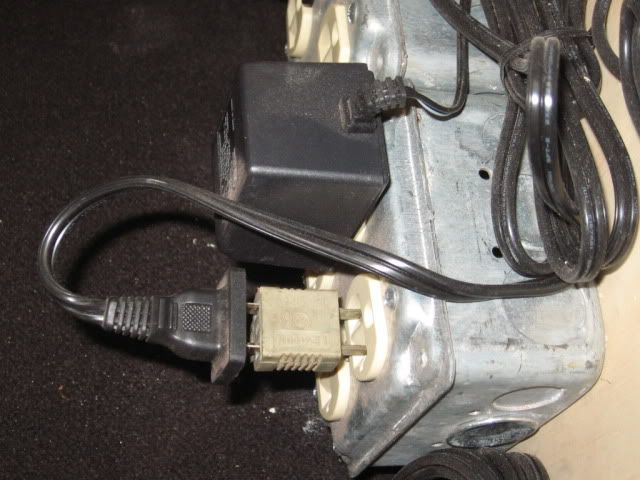
If you can find these adaptors new you may have to grind down the larger prong. These were old, at the shop, took some time to find them. The prongs were the same size.
In our case reverse phasing was obvious. Move an engine from the engine facility, powered by a PH 180, to main line, powered by a Z 4000 and one or both overloads on both transformers would open. Power check from one block, powered by the PH 180, to the other block powered by the Z 4000. Center Rail to Center Rail, which should show 0 volts or at most a few millivolts was 36 volts. Eek Reverse the plug as shown above and all was well Smile

For any set up that we do, one power cord from one wall outlet is used for all layout power. It first comes to the multiple quad-outlets shown above and then to all other power needed. As was state previously power from different 110 volt outlets can also cause phasing problems. That is KIS.

Most recently the input power board looks like this. From here at least one extension cord goes to the transformer module that has (2) Z 4000 powering the (4) main tracks.

The visible DCS TIU only powers the engine facility. Another TIU powers at least (2) of the (4) main lines. Both TIU's have to operate in Super TIU mode.

I don't know how well the 200 ft loop will handle DCS signal. If you have trouble with this on one channel, example: Fixed input #1, you may have to split a loop into two blocks from your TIU location and use Fixed input #1 and possibly Variable input #1 set to fixed voltage. Both TIU inputs could be feed from the same handle of the Z 4000 since you are not really increase track load, it is still one loop, but you have increase signal capacity ability. This would give you two signal generators for such a large loop and the signal circuit is 100ft, still large, v.s. 200 ft. I would see how well the DCS works on this large loop before you go on.
Mike .
Last edited by Mike CT
See Z4000 Phasing (MONK) MTH didn't have a clue. I fixed it by reversing the primary windings. The first clue was that the line cord was backwards, the grouned side was on the switch (common wire)that is a big no no.
quote:
Originally posted by Hot Water:
Well the alternative might be to use your Z4000 to power two of the three main lines, and purchase a Lionel 180 "brick" to power the third main line. Since the 180 bricks are a constant out-put of at least 19 VAC @ 180 watts, you could use that third main line for TMCC operations only.

Concerning phasing of transformers, if your MTH Z4000 is a much older serial number, IT may be the "backwards" transformer. You can contact MTH Service Dept. and have your Z4000 serial number handy. They should be able to tell you if your Z4000 is one of the "backwards ones", then send it into them, and they will correct it for you. That is exactly what happened to me; one VERY early Z4000 for half my layout, and one very NEW Z4000 for the other half. MTH fixed my early model Z4000 at no charge, as they could tell by the serial number it was incorrect.
Last edited by MONK
Post
The DCS Forum is sponsored by

OGR Publishing, Inc., 1310 Eastside Centre Ct, Suite 6, Mountain Home, AR 72653
800-980-OGRR (6477)
www.ogaugerr.com

×
×
×
×
Link copied to your clipboard.
×
×