
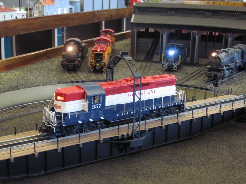
I have a modest size layout and am starting to add electricity to my buildings, stations, etc.   I have already added electric to my lighted engine house (Atlas....I added the miniature lights inside), the MTH station plus 5 extra station platforms, a yard building (small) and a double track cross over people bridge with 8 tiny lights that I added!    Today, I wired in one of my "cities' which consists of 7 MTH buildings, some with add on floors.  After about 2 or 3 minutes of seeing everything lit, the circuit breaker trips.  If I take the city buildings out of the circuit, everything remains on.  Apparently I have reached the capacity of the transformer auxiliary power.  (I am using the 14V tap for everything except the wired bridge which uses the 10V tap)  I know that changing over to LED lighting would probably solve the problem, but I prefer to leave that alone and add another transformer for running the electricity to my cities.  (I still have another city to wire!)

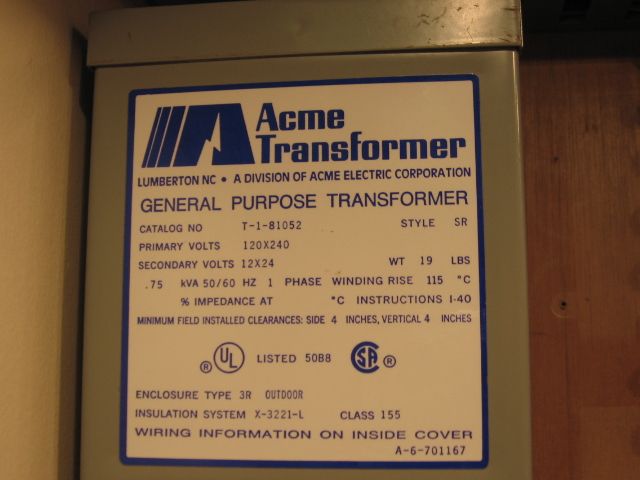
What is a recommended power supply for just adding power to operate cities and accessories.  I run convention, and don't plan on adding DCS or whatever.  Thank you in advance for your assistance.

Original Post

Replies sorted oldest to newest

I'll never forget the first time I saw photos of the famous Lionel 1949 Showroom Layout.  (I wasn't around yet to see it in person. )

Anyway, that jewel of a layout (in its day) used FOUR 275-watt ZW transformers for trains, accessories, track switches, and lights!!!

Best overall advice is to tally up your electrical needs, and perhaps "divide and conquer" so you can safely power various accessories and lighted buildings without exceeding the transformer(s) ratings.  Even the 4 handles on today's ZW-L can deliver 180Watts each, but overall the transformer cannot exceed 620 Watts in total.  So plan accordingly.

David

You want lots of cheap ac power go get yourself a 12v AC landscape lighting transformer from Home Depot or even better, Menards. Ive got one that's dangerously huge at 600 watts. Some will say theyre unregulated and blah blah blah but if you just run accessories with em they work awesome

Accessory transformer upper left in picture. Wired for 12 volts, can be wired for 24 volts.  Input voltage 120 volts, can also be wired for 240 volt input.  .75Kva (Kilo volt amps)  a more than adequate 750 watts.   Transformers like this are normally used as machinery, control voltage, transformers, or as buck/boost transformers, ( to correct voltages as needed, up/down).  Transformer, pictured, was on the shelf at the shop, not used on a larger electrical project. 

To do this properly, you also need a fused (over current protection system) 

Most accessory fuses should not exceed 1 to 3 amps Blue crimp on connector is power-in, from the transformer to the fuse block assembly, (down).  Note the daisy chain solid 14 ga. wiring on the right.  power through the fuses back out to the left, each different accessory. 


Top fuses pictured are 18 volt accessory fuses.  18 volts is power from parallel PH 135's pictured lower left, also used for track power, which has an additional set of track fuses, (no more than 7.5 amps per track circuit).  Most of the 18 volt accessory power is used for Atlas switches, which work well at 18 volts, IMO.  

More Power, Tim.

Be careful out there, Safety meeting of the day. 

You might note that a lot of the low voltage, garden/landscape, lighting systems, using the Malibu transformers, also mentioned in this thread, are done with #10 wire.  

Mike CT


Last edited by Mike CT

The MTH web site indicates that the Z4000 can put out 3amps on the fixed 14v, 3amps on the fixed 10v, and 180 watts each on the adjustable arms. The 14v capacity is a little more than 40 watts, no wonder it tripped. Does anyone know what the four breaker ratings are?

I like mine, it powers only accessories and gives a ton of options to group them at the voltages they like.

I recently switched my accessory wiring over to ATM size fuse/distribution blocks as pictured below. Most of the fuses are 5 amp and the sub feeds then go to distributed terminal strips at several key locations around the layout. The feeds from the power supplies to these fuse blocks are 12 AWG and fused right at the power supply accordingly. So far this has worked really well.

IMG_1365

And if a fuse blows it shows up like so for easy identification.

IMG_1354

Rod

Attachments

Images (2)
  • IMG_1365
  • IMG_1354
Rod Stewart posted:
Matt Makens posted:

If I remeber correctly the accesory breakers are 6 amp and the variable channels are 12 amps

Actually the accessory breakers are 4 amp each and the handle breakers are 10 amp each on the Z-4000.

Rod

Looks like the accessory breakers are 4 amp and the handle breakers are 12 amp. I stand corrected on the latter!

IMG_1405IMG_1408

Rod

Attachments

Images (2)
  • IMG_1405
  • IMG_1408

Prof, the internal circuitry shuts the output off at 10. Something has to be really wrong to trip the breaker.last time I had an issue it had been do long since I'd had one trip I totally forgot they were there. I had bad fets on the green side that would trip the breaker luckily shipping cost more than the parts. I pulled my z4000s off the layout in favor of the Lionel bricks and I use a 600 watt landscape transformer for accessories 

PLCProf posted:

There is no law that says maximum current capability needs to coincide with maximum voltage out. That is a standard assumption with "variac" type transformers, but the switching type stuff is completely different. Using the commonly quoted figure of 10A for the track outputs, 165 VA would occur at 16.5 volts, which is not unreasonable. It may be that 16.5 volts is where the output capability is highest, and that is what is advertised.

I don't have a Z-4000, but it would be interesting to load it up a little above max and see what happens. I would suspect a thermal shutdown would occur without tripping the breakers, but that is just a guess.

I agree. A few years ago I conducted some quasi-scientific research on a Z-4000. I loaded up all four outputs using surplus car headlight bulbs as loads. I was able to pull a max of 12 amps at 13 volts on each track handle output before the breaker tripped. This is about 156 VA x 2 = 312 total VA. Then I loaded the two accessory outputs the same way only I used a handheld meter to read volts and amps. I pulled about 90 VA total from these two outputs, for a total of pretty close to 400 VA; or 400 watts. (This is approximate since the Z-4000 voltmeters and ammeters read only to the nearest volt above 10) As soon as I increased either track output to raise the load the whole transformer crowbarred and shutdown. All lights went dark. Then a slight reduction in the track handle and she came right back online. So the 400 watt output is real. I used a wattmeter to observe the input all the while and it peaked at about 535 watts.

My only real beef with the Z-4000 is the voltage sag with increased load. When you set the handles for 18 VAC with little load, then load it up with a couple of engines running with smoke units, the voltage sags 2-3 volts. To maintain the 18 VAC you have to nudge the handles open a little more. Since they are electronically controlled you would think MTH could have designed it so that the voltage would remain constant with load up to the 165 VA rating of each track output, about 9 amps or so @18 VAC, or until the 12 amp breaker tripped at lower output voltages.

Rod

Last edited by Rod Stewart

hello guys and gals..........

Does anyone have or can part a pot controller for the z4000 (left handle side) I can use with the gear and wire harness already on it so I can fix mine.  Its the only transformer I have to run my trains.  I see some of you guys in this tread seem to be not happy with their Z4000.  I cannot afford to buy new big transformer and mine z4000 is 5 years old.


Tiffany


Last edited by Tiffany
Rod Stewart posted:

I recently switched my accessory wiring over to ATM size fuse/distribution blocks as pictured below. Most of the fuses are 5 amp and the sub feeds then go to distributed terminal strips at several key locations around the layout. The feeds from the power supplies to these fuse blocks are 12 AWG and fused right at the power supply accordingly. So far this has worked really well.

IMG_1365

And if a fuse blows it shows up like so for easy identification.

IMG_1354

Rod

The indication light is a wonderful idea.  As I age, even with lighting, above my control system, it is hard to see the blown fuse/links. 


Last edited by Mike CT
Tiffany posted:

hello guys and gals..........

Does anyone have or can part a pot controller for the z4000 (left handle side) I can use with the gear and wire harness already on it so I can fix mine.  Its the only transformer I have to run my trains.  I see some of you guys in this tread seem to be not happy with their Z4000.  I cannot afford to buy new big transformer and mine z4000 is 5 years old.


Tiffany


You may be able to send it back to MTH for repair.  Both of the Fort Pitt Highrailer Z4000's have been back for repair.


Basic electric.  Volts X Amps = Watts (power), or (a close), VA (va).  It would be nice if they would list the Input amps also. Transformers are relatively efficient machines when comparing input energy to output.   

Another consideration is initial engine(s) start up.  The Fort Pitt Highrailer  Roundhouse/Turntable display has the ability to power as many as 12 engines at one time.  The in-rush or surge when you power on a PH 180, trips the breaker on the brick.  Parallel PH 180's can handle the surge.  Once powered the power consumption, just lights and electronics is relatively low. 


Power supply.


Mike CT posted:

Basic electric.  Volts X Amps = Watts (power), or (a close), VA (va).  It would be nice if they would list the Input amps also. Transformers are relatively efficient machines when comparing input energy to output.   


Mike, How do you interpret the back panel? Also Amps x Volts equal VA. It the Watts that are alway less than VA due to power factor. 

Pete

Another vote for ‘divide and conquer’, but with a slightly different approach.

In order to minimize the length of the wire runs, I installed six remote controlled outlets around my layout, and these supply power to five terminal strips that have a variety of ‘wall warts’ (a fuse added to each) – I have 20 wall warts altogether. The sixth remote outlet supplies power to the track transformers (two ZW-L's) and the turnout power. This allows me to turn on/off sections of the layout, and to the track, which is handy when working on the wiring.

For the operating accessories and lighting, I use 14vAC and 18vAC wall warts, as well as 3vDC, 4.5vDC, 5vDC and 12vDC, according to the accessory requirements. Remember that DC works fine for the incandescent lights.

Alex

Last edited by Ingeniero No1
hokie71 posted:

Rod conducted a neat experiment, is efficiency like 550w in and 400w out typical for small transformers? Seems a lot of loss, a 150w bulb.

I rechecked my notes from the testing I did in 2009, and the peak input wattage just at the verge of shutdown was actually only 535 watts. (I fixed my earlier post) So 400/535 gives about 75% efficiency; which doesn't sound too bad. During the testing the cooling air flow temp increased about 30 deg F above ambient. This represents the 135 watts or so of power loss. Also the Z-4000 pulls about 24 watts of power at ambient, with no output loads at all.

Tiffany; please don't read my discussion about the voltage sag under load (earlier) as a real issue or a negative with the Z-4000. All transformers do the same as far as I know. All in all the Z-4000 is about the best value for the dollar in toy train transformers IMO.

Rod

Last edited by Rod Stewart

Note sure term efficiency can be applied in the same way here. A simple two winding transformer is typically 95-98% efficient. Power going into a Z4000 also is used to power readouts, electronic circuit breakers, horn-bell circuits, and programming and reset circuitry. Also is it a sine wave out or chopped sinewave. The latter requires additional circuitry. Then how is it isolated from the input power. Post War transformers were basically autotransformers connected to the mains. UL doesn't allow that anymore so is there an isolation transformer now feeding an autotransformer?

I don't have a Z4000 or any modern transformer for that matter otherwise I would take it apart to find out.

Pete


Last edited by Norton

Hello All.  Thank you for your responses and advice!  I decided to go with a power supply sold by Radio Shack.  19 amps, 12 volts...(actual voltage is 13.7  VDC).  Regulated, fused and an internal fan to keep things cool.  Small in size and only $69.00.  Had to change some  wiring so that the transformer (Z4000) does not conflict with the power supply.  In other words, the cities and train stations, etc.,  which all use incandescent lamps, are wired only to the power supply.  Works perfectly!  Thanks all again.

Add Reply

Post

OGR Publishing, Inc., 1310 Eastside Centre Ct, Suite 6, Mountain Home, AR 72653
800-980-OGRR (6477)
www.ogaugerr.com

×
×
×
×
Link copied to your clipboard.
×
×