I am in the process of rebuilding a 275 watt ZW transformer and want to replace the whistle rectifier disc with diodes.

I saw some for sale on eBay a 16 amp and a 40 amp by the same seller. I sent aa question asking what the difference was and the reply was the 40 amp was a little more heavy duty.

I remembered a while ago reading about the Zener diodes and how good they were.

I am confused on which way to go. The 16 amp cost less than the 40 and I have no idea which would work best and of course the Zener cost the most but have had good reviews on the forum.

I am leaning on going with the Zener but just would like some feedback here to see if I can make sense out of all this

Thanks!

Dave


Original Post

Replies sorted oldest to newest

PDG,

    You can also drop Jim Lawson, here on the OGR, some private e-mail and ask him exactly what he uses when he rebuilds all the ZW's.  Jim is a great guy and will probably help you with any questions you might have on the full rebuild/upgrade.  I know his choice of Diodes works perfectly, I own several of his rebuilt/upgraded Transformers.  They work better than brand Spanking New.  I recommend his work 100%.

PCRR/Dave 

Last edited by Pine Creek Railroad

Greetings, I actually joined this forum to reply to this thread and share some insight into restoring these.

In the interest of full disclosure I do have a train shop that remains from our antique businesses so there are a couple thousand pieces in my life, and of course I ran into my share of ZWs.

This is not my real job, nor even my real hobby - I restore audio equipment as a hobby and as such generally know which wires not to lick.

that being said, I have 6 zws and found this page when googling info on the copper disc diodes and what people use to replace.  I know its a 3 year old thread, but when I fix a stereo, if there is an old thread I append to it for a simple reason:  I found it thru a google search for info so some day, somewhere, someone else might as well.  new or more info is always good.  The 'net can have good uses too.  ;-)

So, onto the tech data:

The expen$ive replacement$ using the 16A stud diode is fine and good if you want to throw those bones, but not needed.

MOx diodes (metal oxides, like the target copper or the seleniums I see far more of) have very limited voltages and even far more limited currents.  its hard to find any tech data on our copper discs, but using similar seleniums, we can glean:  the single disc is able to withstand the wide open 19.xx OC voltage of the zW.  however, consider the 1 inch 6 plate selenium.  while it can handle the 120+voltages, a 1 inch selenium is good for roughly 150ma of current.  lets say our discs have 2sq inches of usable MOx, I would estimate they pass 300ma of current but suspect more like 200.

the posts by martin above using the NTE 8515 (fwiw I rarely use NTE parts - too generic and questionable sourcing) is very interesting and I essentially copied him.  squeezing the anode in a crimp spade or lug and tying to the metal plate was a REAL GOOD idea.  you can then just ditch the wire from the old disc retention 'nut' and simplify things.

I use on smaller transformers (like the 1033) the 1N5405 (500v, 3a) and I just ordered a passel of OA60 6 amp diodes from parts express at about .46 cents each.

This should appease anyone that buys my refurb ZWs but in reality, I have a ton of 1N4007s that should do just fine.

Why?  the DC offset triggers a specially wired solenoid in the tenders which then powers the whistle or whatever from track current.  ya, the ZW can source a lot, but the reality is, the whistle will run all day on a few hundred mA.  To draw AMPS would require an air raid siren in the tender.  and the newer digital stuff draw almost nothing to detect the whistle signal.

we have breakers in the ZW which are a thermal type, they require a lot of current for a lot of time to activate and we all know, in the meantime wires can and do catch fire.  IIRC the wisdom years ago was to use a 3-5 amp breaker inline with the track wiring and loco, lit cars, caboose, whistle, never tripped it.

The last zw I just did used 2 5405's in parallel I an have no doubt it would live long and prosper.  What about a derailment short while blowing the whistle?  the 5405 has a 200 amp surge rating EACH.  so I should survive at 400A.

Also consider, MOx diodes have a crap ton of resistance.  I use as a rule of thumb when doing for example a tube radio with a 6 plate Se rectifier, replacing the (usual) 22ohm inrush resistor AND the Se with a 120-150ohm 5-10w cement, then this teeny tiny 1N400x diode.  That being said the resistance of the Se is 100ohms plus, or about 16+ ohms per place.  Our copper should be similar.  when the whistle is running the wires from the throttle has for all intents and purposes 0 ohms and the whistle control 16ish.  meaning all the running current will come from the throttle.

I have 4 more Zws on the shelf to do and I will do the next one with 1N4007 and blow the whistle all day just to test it...


thats all for now.


ps:  does anyone know how to start MTH PS1 equipment that will make idle sounds but when you try to leave neutral on the electronic E unit, they make a single 'tink' noise and repeated trys will go tink-tink up to 8 of them, then cycle back to 1.  what sort of state is it in ?  I have 4 never run locos doing that....

Quaddriver posted:
...the whistle will run all day on a few hundred mA.  To draw AMPS would require an air raid siren in the tender...

How about the current draw through the rectifier on a ZW when blowing the horn at full throttle on a 2343 A-B-A with 6 illuminated 2500 series passenger cars? What do you estimate that to be? With remote switch's bulbs and their controller bulbs on the layout, it could be 7-9 amps pretty easily.

that is an interesting point....if I am reading the zw schematic correctly (and it is written HORRIBLY) the 5v compensating winding is put in parallel with the fixed 8 and variable 12 and is dc - it is a popular, old fashioned way of doing signalling (like ringing a phone for example.  the Cu rect has a 1.5 ohm resistor in series with it which means the absolute current on a shorted rectifier is 3.33 amps.  BUT, the working Cu rect has its own resistance.  I cannot find a spec on it, but its at least 1 ohm.  (simply because the old general electric test was to forward bias it with .5v and read .5a and reverse bias it with 2m and read at most .0025a (2.5 mA)

a silicon rectifier removes this internal resistance to one that is negligible.  I need to think a minute what this can mean when the AC voltage is low but Im thinking since the fixed secondary is always 8, its not a problem.


keep in mind the piv of the Cu rect is 8v.  apply more than 8v on the reverse and it burns up...

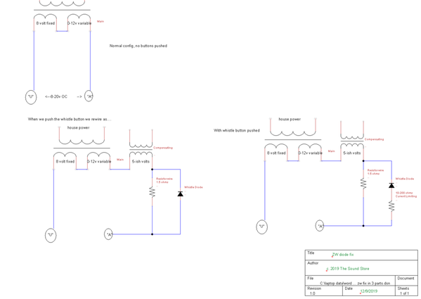
I had to poke and probe another 'virgin' zw with the lionel service data to understand the schematic.  you are right, the compensating oil is in series, its the diode itself that is in parallel with the resistor.  I am going to try and import an image of 3 schematics, 1st is ZW in normal mode, 2nd is ZW with whistle button pushed, 3rd is what we should convert them to...

here goes...

zw fix in 3 parts

hopefully that shows up, I can send the souce 'photo' or the tinycad file.

But anyways, I am measuring between 200 ohms and 800 ohms fwd or rev across 2 Cu discs I have, both measure a Vf drop of 1.7v dropping quickly to .8v then slowly dropping... and reversed biased about 70mv Vf (meaning it leaks)

So we can now conclude that a stock factory Cu disc has small current flowing across it.

The problem is the Si diodes we now use have no current limiting.  if you follow the second schematic and impose an AC signal across it we find that when A+B+C transformers (8v, variable, compensating) are pushing the positive sine wave towards terminal "A", the diode is reversed biased and supposedly no meaningful current flows across it and all the current flows thru the shunt resistor.

However when terminal "U" has the positive part of the sine wave, with the internal resistance of the Cu Disc, a small DC current flows and the majority of the positive sine wave flows thru the shunt.  classic line signalling.

Replace this with silicon and part 1 is the same, when the sine wave is positive going to the A terminal the new silicon is reversed biased and zip flows and all current flows thru the shunt up to 16 amps as set by ohms law. 

But when the opposite is true and the sine wave is positive at the U terminal, then the current divides nicely down the shunt and the biased diode.

The value of the current flowing is going to be determined by the effective resistance seen, the motor in the loco, all the lights in cars, track etc.  On the 90 watt? 1033s with a 3 amp diode - likely safe. 

from my 3rd schematic, to avoid all of this we need a resistor anywhere from say 10-200 ohms to start, to find the largest resistor you can use to activate the weakest whistle solenoid you can find.  (If you run modern equipment like MTH PS, they require so little to fire off...

I need to find a whistle tender to glean what the solenoids require to fire - that would be the easiest way

One last thing, pay attention to the ORIENTATION of the diode.  I lifted this from the lionel service data.  the A+B+C output AND the 1.5ohm wire attach at the cathode, which, is the metal frame it is mounted to.

Anode cased 16amp diodes and the NTE 8515 and my 1N5405/OA60 diodes...we have hooked them ALL up backwards!

(but no one is complaining stuff has blown up!)

lastly, from the condition of contacts I see, there is no arcing.  Im betting with silicon in there, no inrush resistor, you get some great sparks when engaging the whistle.  No one is making replacement contacts anymore - just sayin....stay tuned.

Attachments

Images (1)
  • zw fix in 3 parts

Add Reply

Post

OGR Publishing, Inc., 1310 Eastside Centre Ct, Suite 6, Mountain Home, AR 72653
800-980-OGRR (6477)
www.ogaugerr.com

×
×
×
×
Link copied to your clipboard.
×
×