
Here's a little board I am thinking of releasing, it's a fairly simple relay based signal driver for insulated rails.  This gives you a reliable method of using the insulated rail to trigger a variety of signals and eliminates any chatter due to poor contact as the train enters and exits the zone.  This comes up repeatedly, I figured maybe there's room for a cheap solution.  It adds a choke for DCS compatibility, and the power draw is only around 20ma from the track.  The resistor offers inrush protection so that you don't get arcing and electrical noise when charging the capacitor.  The board footprint is less than 1" x 2" and it has mounting holes to attach it under the benchwork.  It also has two sets of SPDT contacts for maximum flexibility for signals, etc.

Track Presence Sensor Schematic

Track Presence Sensor 3D View

Attachments

Images (2)
  • Track Presence Sensor Schematic
  • Track Presence Sensor 3D View
Last edited by gunrunnerjohn
Original Post

Replies sorted oldest to newest

I think that's a good idea. I don't recall seeing much (or anything) like this for 3 rail. I do think it would fill a need and would be worth a try. Of course, if you posted the gerber files and parts list I would certainly try this one myself at the inexpensive PCB maker you found (forgot the name).    It just might be too good of an idea to do that with though.

We are discussing the IR detectors in another thread (ITADs and Making Your Own) and the IR devices are, so far, having some problems, but more things to try are in the works. Your input is welcome, BTW, if you haven't been there already. 

Last edited by rtr12

John

Looks like another winner. I have been using the SPDT version based on input from you and Stan 2004  in the past with no problems. I have also been looking at A DPDT version using the same relay with terminal boards for ease of connection as shown above. I'm sure this will go over big wheather it be in kit form or completely assembled for those who are adverse to assembly and soldering.

Gerry

I have a couple of prototype PCB's coming, and I am trying to line up cheap components.  Note that I used all thru-hole stuff as that's typically easier to get cheaply and also makes it easy to build.  Maybe there'll be some low cost kits in the future.   It's a basic circuit, and one I've been using on our club layout hand building them.  I figured I'd like to have about 15 of these myself to replace the hodgepodge of stuff we use.  I did find some nice terminal blocks for a very good price and ordered a bunch of them.  I know I can use them somewhere if not here.

That thought crossed my mind, but I've been using this relay in a similar lashup for a long time with no ill effects.  It has a 15ma coil, so any kickback seems to get lost in the cap.  I've had them running several years running signals, still running.

In the off chance that it should prove to be an issue, I left provisions for an SMT diode at D2 on the left.

Attachments

Images (1)
  • mceclip0
Last edited by gunrunnerjohn
gunrunnerjohn posted:

That thought crossed my mind, but I've been using this relay in a similar lashup for a long time with no ill effects.  It has a 15ma coil, so any kickback seems to get lost in the cap.  I've had them running several years running signals, still running.

Thanks John. Perfect timing. I had a call today from a friend asking about IR devices and I said there were better ways. Will look forward to your new product introduction.

Lou N 

Well, I have to get some parts in and actually assemble a few for final tests.  Since it's a circuit that I've been using, I really just want to see the boards and make sure the components like the terminal strips and the like actually fit with the current layout.  I've been burned too many times buying a bunch of boards, only to find out I made some spacing error!

Lou, see previous post, I added a SMT diode on the end in case for any reason I deem the diode should be there.  I didn't want to make the board any larger for the full sized diode.

I would definitely take some too. Kinda what I was getting at at my earlier post referring to the gerber files and trying it myself. Assembled, kits, boards with parts list, any way is fine with me. I do like the idea of the through hole components for the kits though, I think many other will too. But I do need to try that SMT stuff one of these days.

Also, I still haven't forgotten trying the Watchdog devices. I'm still missing some parts for the layout changes I want to make. If I don't get them pretty soon I will go ahead and try them and rework things later on.

John:

Am I reading the diagram right as you show the relay being powered by the “center rail”?  If so, that means it can be powered from an AC transformer thereby eliminating the need for a separate DC power supply, which is another selling point. 

But why connect it to the center rail?  Why not an accessory power terminal instead because in conventional layouts the power to the center rail is quite variable. 

Bill

gunrunnerjohn posted:

There's no reason at all why the unit couldn't run from any aux power source, AC or DC for that matter.  I confess that I'm always thinking command operation and I always have 18 volts handy on the center rail.  It just needs a voltage that has a common with the outside rail.

John:

Thanks for verifying that as it will greatly reduce the complexity.  Be prepared to sell out at York!

Bill


BruceT47 posted:

Nice job John!  Is there any provision or perhaps add-on module that would add time delay to this. Thanks.

Bruce

I'm surprised it took so long for someone to suggest this.   I confess that thought crossed my mind.  The attraction of this design is that it's simple in concept and execution.  If I started adding features, I don't know what would make the most sense.

mike g. posted:

Nice John, if you get around to selling them are they going to be as easy as these?

20100 Passenger Car LED Lighting Kit

Even easier, all screw terminals for the connections.

Bobby Ogage posted:

I need a gizmo like your circuit to trigger Rail King crossing gates, Rail King crossing flasher signals, a K-Line shanty signal man, and the signal man inside a Rail King boxcar. If your circuit is rugged enough to handle these loads individually, I will be a customer.

The relay contacts on these are rated at 2 amps.  It was a tradeoff on price/size/power handling.  Higher capacity relays are larger and, have more coil current, and are typically more expensive.  I suspect most of the stuff you mention shouldn't need 2 amps, but I'm not sure of everything.

DSC_0024DSC_0025I have been using these similar boards. Unfortunately, the company no longer exists. With the jumpers they have endless possibilities: timers, flashers, one on one off combos, etc. I have four and one for lighting also. They still need an isolated rail input, so that is why I was looking into the ITAD possibilities for track I didn't want to rip up. They make hooking up signals and gates much easier, as would John's. With diodes on the inputs, I can hook more than one on the same relays, like a signal bridge and crossing gates for two track operation. Great idea, John. Your little gray cells are always at work.

Attachments

Images (2)
  • DSC_0024
  • DSC_0025
Last edited by John H
gunrunnerjohn posted:
rtr12 posted:

But I do need to try that SMT stuff one of these days.

SMT boards can be a lot smaller, but it is more trouble to assemble them.  Obviously, for stuff that I sent out to an assembly house I use SMT, things like the Super-Chuffer would be impossibly large with thru-hole parts.

Probably just a try would be sufficient for me, don't think I would want a steady diet of SMT to assemble. Sending those out sounds like a good plan to me. I am amazed at how small things can be made with SMT.

I think the time delay suggestion above might open the door for another module, but I think you are right to keep these simple and as they are. I think there would be many more users that way. You could add the time delay, larger relays, flashers or whatever in separate modules later if the demand is there. A modular system so to speak. 

I finally figured out how to set up individual relays and you have to go and make something simple.  For those using Command, while John is setting these up to draw track power I like to use AUX 14 volts to power the relay(s) and signals.  The reason being I sometimes forgot to shut down the layout, having all of the signals lite up is a visual que to me to shut things off before going to sleep.  Also, if I have an un-powered but occupied section of track (hidden return loop) I don't want any surprises when I power up that section.  A red signal is a sure sign that something is under there.  

Henry

clem k posted:

I have never done isolated rail thing, how long does the isolated rail have to be and how far from the grade crossing protection can it be ? Also will this work with Z Stuff?

The insulated rail can be any length, and it can also be in any position.  It really depends on what you're using the signal capability for.  We have some on the club modular layout that are 20-25 feet long or more, they protect a couple of long tunnels that otherwise we could have issues if someone stops or gets stuck in there.  There's a signal at the entrance, and right past the signal, the insulated rail starts until the tunnel exit  We have some insulated rails that are shorter and are for crossing signals.

rtr12 posted:

Probably just a try would be sufficient for me, don't think I would want a steady diet of SMT to assemble. Sending those out sounds like a good plan to me. I am amazed at how small things can be made with SMT.

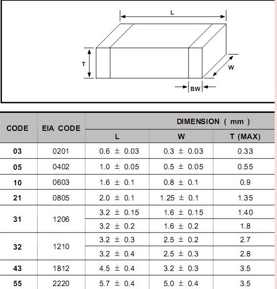
 Yep, I only assemble what I need for prototypes or small low count projects.  I also have learned quite a bit about laying out a design for easier hand assembly.  Positioning the parts for easy soldering, and also picking sizes that are reasonably easy to handle are key.  I did one design early on and I specified a size 0201 resistor!  I don't don't know if you realize how small a 0201 resistor really is!  Check the table below!  I couldn't even see to position it using my desk magnifier, and forget about soldering it!  I've since set a self-imposed lower limit of 0603 parts with a preference for 0805 or larger.  I also steer clear of any multi-pin part at a spacing of less then about .095mm between pins.

rtr12 posted:

I think the time delay suggestion above might open the door for another module, but I think you are right to keep these simple and as they are. I think there would be many more users that way. You could add the time delay, larger relays, flashers or whatever in separate modules later if the demand is there. A modular system so to speak. 

 There's always room for a future product that does much more.  If I went that route, I'd probably consider a uP based project to give me a lot of flexibility.  A uP with a nice big jumper field for options would provide lots of flexibility, but it would also carry a higher price tag.  There are always tradeoffs...

Oh goody.  Now I don't have to use your LED lighting module to control a 99 cent eBay relay module for insulated rail sensing!   Now it's all on 1 board!     Video of GRJ's LED board drafted for insulated rail duty in this post.

ogr%20block%20relay%20experiment

Looking good GRJ!   BTW take a look at R1 for 14V Aux power operation.  If using the HK19 relay with 400 ohm coil that 620 ohm divider may not provide the minimum 9V spec to trip the 12V relay.

Not sure how many applications need the 2nd pole but just wondering about mixing the 6-position terminal screw strip connector with a 3-pin header.  For the average guy those 0.1" square-pin sockets are a nuisance if you don't have the crimp tool, soldering iron, whatever.

Also, in the creeping-features category, as mentioned earlier one sometimes useful feature of ITADs is the settable time-delay.  Like that optional SMT diode you tossed in for coil flyback (I concur it's not needed), I'm "imagining" a 50 cent optional SMT circuit to insert a settable time-delay.  Would require continuous power so would add another terminal to "ground" (outer-rail).

Attachments

Images (1)
  • ogr%20block%20relay%20experiment

The three pin header was just to allow use of the second set of contacts.  My feeling was that a vast majority of the users would not need or use them.  The resistor is indeed sized for 18 volts, for a lower voltage, the resistor would also be changed in value.  I suppose I could leave that one unsoldered and include a couple of choices in the package for various input voltages.

Stan, I thought about an "enhanced" model, but I've found this to be pretty useful in our own setting, so I figured I'd float this one first.

I just realized I didn't address the last part of your comment Stan.  I'm using the HK19F-DC12-SH2C with the 720 ohm coil.

Last edited by gunrunnerjohn

Holy mackerel, those 0201 items are only .001" x .002" according to the Google mm to inch calculator. That is TINY! I wouldn't want to try one of those, I will take your advice on that one and stick to the 0603 minimum. I think those little square chips with lots of little tiny fingers on all four sides would be pretty ugly as well. It's amazing they can get the robots to do that stuff. Probably have to pay them more, TINY duty pay. 

I guess on the good side those would certainly allow some very small PCBs.

rtr12 posted:

Holy mackerel, those 0201 items are only .001" x .002" according to the Google mm to inch calculator. That is TINY! I wouldn't want to try one of those, I will take your advice on that one and stick to the 0603 minimum. I think those little square chips with lots of little tiny fingers on all four sides would be pretty ugly as well. It's amazing they can get the robots to do that stuff. Probably have to pay them more, TINY duty pay. 

I guess on the good side those would certainly allow some very small PCBs.

You read that wrong. 0201 is .024 x .012. Inches!

Thats still big. We use 01005 in cochlear implants at work. Thats .016 x .008. There is now a size smaller!

We have to use solder stencils that are .003 etched stainless so that the solder paste isn't higher than the part. 

Lou N


A bit off topic of the thread, but he entire process of using solder paste and pick and place machines is completely fascinating to me.  Here's a good walk-through of the process used for machine-assembled boards: 

For anyone that is interested in electronics, btw, the EEVblog is a wonderful youtube channel with countless hours of content on all aspects of electronics, including basic components and theory, product tear-downs, in-depth theory, and BS-gadget-debunking.  Oh and in case anyone's interested, the circuit being built in the above video is a device that allows more accurate current reading at micro and milli amps when using a digital multi-meter.  

JGL

John,  great idea!  I built several relays using a design that was published in CTT several years ago,  the parts were available from Radio Shack,  your design would be a big upgrade and easier to use.  Since the Radio Shacks near me are no longer, sourcing parts are not easy either.  I like the idea of having kits available for those that need several.

Best wishes,  Dave

JohnGaltLine posted:

A bit off topic of the thread, but he entire process of using solder paste and pick and place machines is completely fascinating to me.

JGL

Those are big parts and really slow machines.  But it demonstrates whats happening. 

Let me know if you ever come to cleveland. I'll show you machines that put down 17000 parts an hour. 

I work here:  www.valtronic.com

Lou N


Hey John,

Great idea to provide this feature in a plug-n-play (of sorts) module. To keep cost down, could you use one of the many 2-relay modules from the bay, which already have LED's, isolation, CONNECTORS (!) and are priced at a little over a dollar ($1.10, $1.35 . . )?

Like this one - and just add your smaller board with a few components and a two-screw terminal block

Relay x 2 module

Good luck and keep us posted.

Alex

Attachments

Images (1)
  • Relay x 2 module
Last edited by Ingeniero No1
Lou N posted:
rtr12 posted:

Holy mackerel, those 0201 items are only .001" x .002" according to the Google mm to inch calculator. That is TINY! I wouldn't want to try one of those, I will take your advice on that one and stick to the 0603 minimum. I think those little square chips with lots of little tiny fingers on all four sides would be pretty ugly as well. It's amazing they can get the robots to do that stuff. Probably have to pay them more, TINY duty pay. 

I guess on the good side those would certainly allow some very small PCBs.

You read that wrong. 0201 is .024 x .012. Inches!

Thats still big. We use 01005 in cochlear implants at work. Thats .016 x .008. There is now a size smaller!

We have to use solder stencils that are .003 etched stainless so that the solder paste isn't higher than the part. 

Lou N

Thanks. You are right, I entered .06 & .03 mm instead of 0.6 & 0.3, was looking right at GRJ's chart when I did it too...duh. I thought that was awfully small.  Those implant parts really are small! I saw some automated PCB manufacturing in the late '80s. Boards were much larger and so were the parts, but still impressive. I can only imagine what they have now. I am going to watch JGL's video to find out.

Last edited by rtr12

Tons of stuff you could add to it, but I have to stop somewhere.  

I know that there are smaller parts, but when you're trying to put something together with tweezers and a soldering iron, the 0201 is 99% impossible, and smaller stuff gets to 100% impossible.   I find that 0603 and larger are fairly easy to deal by hand.  I'm getting to be an old fart as well, so maybe someone with 22 year old eyes and rock steady hands might be able to use the smaller parts, I'll leave it to such folks to try.

Alex, I've done things that depend on eBay products, but it seems I frequently get burned as they fade out and aren't available anymore.  I'm depending on such modules less and less and sticking to parts that I should be able to source for the foreseeable future.

Ingeniero No1 posted:

I agree. I have bought a number of 'modules' of different types from the bay, and when I have gone back for more, the same one I bought may no be available, but a similar one is. I understand how this may be a problem for any sort of production runs that me be done at different times vs just one single run.

Exactly.  If you're just creating a one-time solution, then the eBay modules are certainly the way to go as they're dirt cheap, far cheaper than I could ever do similar functionality.

Chugman posted:

John, I'm pretty ignorant as to exactly what your board can or can't do.   Presently I am using  one outside rail for a common and the other is isolated for signal detection.  If I make both outside rails common, can I use this board to detect train presence?

Nope, it uses the insulated rail.  The board is very simple, it's just there to eliminate any chatter and also provide totally isolated and sets of contacts to operate signals and accessories.

I did some "thinking" and a brief bench test of my design and came up with a couple of improvements.  I decided to add a low value resistor and the cap, then the larger resistor to drop the voltage for the relay coil.  This allows the capacitor to charge much quicker, and the 100 ohm resistor limits the inrush current to avoid arcing at the wheels.  The capacitor also has a higher voltage so that it has a larger delay before allowing the relay to drop out.  I also used more reasonable sizes for the discrete components and changed the relay flyback diode into a thru-hole part since there was room to do so.

Track Presence Sensor For Insulated Rail 1.2 SchematicTrack Presence Sensor For Insulated Rail 1.2 PCB BottomTrack Presence Sensor For Insulated Rail 1.2 PCB Top

Attachments

Images (3)
  • Track Presence Sensor For Insulated Rail 1.2 Schematic
  • Track Presence Sensor For Insulated Rail 1.2 PCB Bottom
  • Track Presence Sensor For Insulated Rail 1.2 PCB Top

I'm giving thought to leaving out the one resistor and including a couple different values in the package, so you can "tune" it for the voltage you have.  Being a thru-hole design, it's simple for most anyone to solder the correct value resistor into place for the specific voltage you're running the relay coil at.  Obviously, I don't care what voltage you use on the relay contacts.  The values in the schematic are good for 16-22 volts AC on the track, but if you had 12 VAC, you'd probably want a lower value resistor.

I'm hoping the Chinese get my terminal strips and relays here so I can put a couple together.

gunrunnerjohn posted:

I'm giving thought to leaving out the one resistor and including a couple different values in the package, so you can "tune" it for the voltage you have.  Being a thru-hole design, it's simple for most anyone to solder the correct value resistor into place for the specific voltage you're running the relay coil at.  Obviously, I don't care what voltage you use on the relay contacts.  The values in the schematic are good for 16-22 volts AC on the track, but if you had 12 VAC, you'd probably want a lower value resistor.

I'm hoping the Chinese get my terminal strips and relays here so I can put a couple together.

Well, let's see, 12 volts divided by 720 ohms is about 17 mA.

Why don't you just feed the coil with a CL2 at 20mA and it will adjust itself!

PLCProf probably has a much better idea (I didn't know where the CL2 would go?), but I was thinking of maybe having both resistors with a jumper to switch between them for the different voltages desired, like high or low (resistors are a little easier than the CL2, more my speed).

After looking at the maximized use of space on the board, I imagine that would probably make the board bigger and wouldn't be so desirable? Anyway, just a thought, but I defer to you and PLCProf (and Stan if he stops by).

Last edited by rtr12

As a card-carrying member of the Peanut Gallery, I concur with PLCProf's idea of the board taking care of the voltage difference.  I think the CL2 is a sole-sourced component so I'd go with a voltage regulator rather than a current regulator using, say, the widely available 78L12 12V regulator (10 cents) which is half the cost of the CL2.  I don't know what percentage of customers would run this with 18V AC command voltage vs. 14V AC aux/acc voltage vs. 12V DC...but I think shipping multiple resistors is a logistical rabbit-hole.  But it's GRJ's party and it's rude to insult the host! 

Actually, the peanut gallery is curious about the Ground terminal that presumably connects (optionally) to track outer-rail Ground...but then goes nowhere (N/C) on the board. 

I like the CL2 or regulator idea, it simply never occurred to me!  This is why I post, someone always comes up with a great idea at the last minute  Since I only ordered a couple of prototype boards, I think I'll make the change.  Thinking about it, Stan's idea of the regulator is probably a bit cheaper, something to be said for that.  FWIW, since I'll have to wait for boards anyway, the 78L12 is only a little over 3 cents shipped from Hong Kong.  The regulator should allow operation down to 9-10 volts AC, the low current draw of the relay will allow the cap to charge close to peak voltage.  Ding...ding...ding... we have a winner!   I'll still leave a small resistor in front to limit the inrush current, maybe cut it down a bit, 47 ohms or so.

The ground terminal is really just to allow you  to have a junction point.  I had given some thought to a .1" jumper that would connect the ground to the common of one set of relay contacts, but I didn't do it.  That would probably make it more useful.  Let me mull that one over...

Just waiting on the terminal strips to come from China so I can do a trial fit and insure the layout is good.  When that happens, I'll order a batch of boards.

I did add a couple of options, might as well while it's still only on paper.

I expanded the ground center common to ground or power to the common of the #1 set of relay contacts.  If you want to power something like an LED signal directly, you don't need any aux power, just use track power with a diode and resistor.

I also added an off-board expansion capability for the capacitor.  This will allow you to extend the time the relay stays closed after the train leaves the insulated rail.  I got to thinking that maybe someone would want a longer delay...

Track Presence Sensor 1.2 Schematic PCB BottomTrack Presence Sensor 1.2 Schematic PCB TopTrack Presence Sensor 1.2 Schematic

Attachments

Images (3)
  • Track Presence Sensor 1.2 Schematic PCB Bottom
  • Track Presence Sensor 1.2 Schematic PCB Top
  • Track Presence Sensor 1.2 Schematic

That's the goal.  I have all the parts except for the terminal strip, I'm using the Euro style terminal blocks.  In order to keep the price of parts reasonable, I ordered a bunch of these from China, they're not here yet.  All the other parts are in.  I want to get the terminal blocks and verify fit for sure before I order 100 or more boards, it would really bum me out to have another fiasco like the WD Generator issue where I had to scrap the first batch of boards because I was in a hurry to get them.

Attachments

Images (1)
  • mceclip0

John:

Great product!  I may buy one to use a spare for my 40-year 12-volt AC DPDT relays now in use for the last 20 years on their 3rd layout.

But following up on my comment from a few weeks ago, assuming that you're going to provide a copy of the schematic with each sale, I think it would be helpful to change the nomenclature on the J1 #5 terminal to not say “center rail” for those that run in conventional mode.

I run both command and conventional but some of the conventional-only runners may not understand that it should not be connected to such a variable-voltage source as the center rail of a conventional layout.

Bill


John:

gunrunnerjohn posted:

That's the goal.  I have all the parts except for the terminal strip, I'm using the Euro style terminal blocks.  In order to keep the price of parts reasonable, I ordered a bunch of these from China, they're not here yet.  All the other parts are in.  I want to get the terminal blocks and verify fit for sure before I order 100 or more boards,it would really bum me out to have another fiasco like the WD Generator issue where I had to scrap the first batch of boards because I was in a hurry to get them.

John:

Take your time and avoid the stress of "fiascos".  All of us are currently operating without these boards so we can all wait a little longer.

That said, when all the parts are finalized, if these units are still in the ballpark of $10 -- and they help to avoid chattering -- you can sign me up for 5 to start.

If you need help writing an installation manual that can be followed by most users, I'd be happy to volunteer to proofread whatever you come up with.  I wouldn't know a "CL2" if it walked up and handed me a grilled cheese sandwich, but I do know how to write procedures that anyone can follow...

Thanks for taking the initiative on this.

Steven J. Serenska

Dan Padova posted:

So if I understand the device correctly, will it operate trackside accessories like a crossing gate, etc. ?  I run strictly conventional.  I use an insulated outside rail to operate such accessories.  

Great minds, Dan, as I just saw this thread and your post anticipated my question.

Same for me. PW style layout with gateman, switch tower, & the usual signals (block, semaphore, etc.) all activated by insulated track sections. They work OK but the action can be balky at times. Also lots of rail sparking.

So wondering if these devices would be suitable for that purpose.

johnstrains posted:
Dan Padova posted:

So if I understand the device correctly, will it operate trackside accessories like a crossing gate, etc. ?  I run strictly conventional.  I use an insulated outside rail to operate such accessories.  

Great minds, Dan, as I just saw this thread and your post anticipated my question.

Same for me. PW style layout with gateman, switch tower, & the usual signals (block, semaphore, etc.) all activated by insulated track sections. They work OK but the action can be balky at times. Also lots of rail sparking.

So wondering if these devices would be suitable for that purpose.

Judging from the first post in this thread that is the designer's (GRJ) intended purpose for this device.  I made a similar one from an article in CTT, parts from now mostly defunct Radio Shack.  Works well but it's kinda bulky and not as sophisticated as John's version (no choke, no inrush protection).  I'm hoping a kit will be made available, I could use a few more.

Pete


My Version

Attachments

Images (1)
  • My Version
Dan Padova posted:

So if I understand the device correctly, will it operate trackside accessories like a crossing gate, etc. ?  I run strictly conventional.  I use an insulated outside rail to operate such accessories.  

Yep, that's the intended audience.  It will provide bounce-free activation of anything triggered by the insulated rail.  It will be powered by the track or by an aux power supply, your choice.  For command, it's obviously easy to power it with track power, for conventional, you will likely want to use an aux fixed supply.

A key design target is to minimize the arcing at the wheels when activating the attached accessories.

Last edited by gunrunnerjohn
gunrunnerjohn posted:
Dan Padova posted:

So if I understand the device correctly, will it operate trackside accessories like a crossing gate, etc. ?  I run strictly conventional.  I use an insulated outside rail to operate such accessories.  

Yep, that's the intended audience.  It will provide bounce-free activation of anything triggered by the insulated rail.  It will be powered by the track or by an aux power supply, your choice.  For command, it's obviously easy to power it with track power, for conventional, you will likely want to use an aux fixed supply.

A key design target is to minimize the arcing at the wheels when activating the attached accessories.

It looks like I've misunderstood the purpose.  

I know yours works with an insulated rail, but to put this in Lionel contactor terms, it seems like your device would be a substitute for a 145C contactor where the passing train completes a circuit (e.g., to activate a gateman).  This would be versus a 153C contactor where the passing train either interrupts a circuit and/or diverts the current from one circuit to another (e.g., from the green bulb to the red bulb on a 153 signal).

Or am I completely misunderstanding and your device can do both?

Please advise.

Thanks.

Steven J. Serenska


gunrunnerjohn posted:
WftTrains posted:

I run both command and conventional but some of the conventional-only runners may not understand that it should not be connected to such a variable-voltage source as the center rail of a conventional layout.

Valid point, I can certainly cover that in the instruction sheet as well.

Well, as long as you didn't choke on the regulator idea.....

I didn't work the math all the way through, but if you were to use a 6 volt relay and 6 volt regulator, or a 5 volt pair, you would have a truly universal design that would work on 6 - 24 vac, both conventional and command. You would need to go bigger than a TO-92 regulator to handle the dissipation at the higher end of the voltage range. I would expect a TO-220 package would handle it without a heatsink, you need about 1 W rating for continuous operation of a 6 volt 180 ohm relay with 24 VAC in.

Just sayin'

I would take at least 4 of these! Kit or assembled, either way is fine. Just in case I haven't said that already, I don't want to miss the boat with all the requests coming on so quickly. 

Also, no hurry on my account either as other have said, I can wait until you are ready at your leisure. I know you have a lot of other things to do too.

Serenska posted:

It looks like I've misunderstood the purpose.  

I know yours works with an insulated rail, but to put this in Lionel contactor terms, it seems like your device would be a substitute for a 145C contactor where the passing train completes a circuit (e.g., to activate a gateman).  This would be versus a 153C contactor where the passing train either interrupts a circuit and/or diverts the current from one circuit to another (e.g., from the green bulb to the red bulb on a 153 signal).

Or am I completely misunderstanding and your device can do both?


It will certainly replace the 153C contactor, it has both a normally-open and normally-closed set of contacts.  In point of fact, there is actually another set of contact on the board to a second header so you get even more functionality.  Also, there is a jumper option to allow you to apply either power or ground to the center common contact, or you can isolate it and connect your own.  It more than replaces the 153C.

PLCProf posted:

Well, as long as you didn't choke on the regulator idea.....

I didn't work the math all the way through, but if you were to use a 6 volt relay and 6 volt regulator, or a 5 volt pair, you would have a truly universal design that would work on 6 - 24 vac, both conventional and command. You would need to go bigger than a TO-92 regulator to handle the dissipation at the higher end of the voltage range. I would expect a TO-220 package would handle it without a heatsink, you need about 1 W rating for continuous operation of a 6 volt 180 ohm relay with 24 VAC in.

How does this look?  I took it a step farther.  Since I already have the components for the first run, I left the TO-92 regulator in place, but I put a TO220 regulator in parallel with it.  I can use either one, so if I find the 5V relays, I can drop them in, all other functionality remains the same.  The only thing that changes is the regulator and the rating on the relay coil.

Track Presence Sensor 1.2 Schematic

Attachments

Images (2)
  • mceclip0
  • Track Presence Sensor 1.2 Schematic
Last edited by gunrunnerjohn
gunrunnerjohn posted:
Dan Padova posted:

So if I understand the device correctly, will it operate trackside accessories like a crossing gate, etc. ?  I run strictly conventional.  I use an insulated outside rail to operate such accessories.  

Yep, that's the intended audience.  It will provide bounce-free activation of anything triggered by the insulated rail.  It will be powered by the track or by an aux power supply, your choice.  For command, it's obviously easy to power it with track power, for conventional, you will likely want to use an aux fixed supply.

A key design target is to minimize the arcing at the wheels when activating the attached accessories.

Thanks John.  It sounds like something I can definitely put to work.  By the way, your signature mentions Hennings.  Will you be selling these through them or directly ?

It will certainly replace the 153C contactor, it has both a normally-open and normally-closed set of contacts.  In point of fact, there is actually another set of contact on the board to a second header so you get even more functionality.  Also, there is a jumper option to allow you to apply either power or ground to the center common contact, or you can isolate it and connect your own.  It more than replaces the 153C.

John:

Thanks.  All understood. The way people were talking about using it to run gatemen, semaphores, and gates, I got confused.

Using this for block control (like a 153C or an insulated rail connected to a chatter-y old fashioned relay) is what I'm after.  I'll take 5 whenever you finalize the design and production.  Like RTR12, there's no rush on my part.  Please take the time to get it right at a pace that's enjoyable for you.

Thanks for doing this.

Steven J. Serenska


Last edited by Serenska

Add Reply

Post

OGR Publishing, Inc., 1310 Eastside Centre Ct, Suite 6, Mountain Home, AR 72653
800-980-OGRR (6477)
www.ogaugerr.com

×
×
×
×
Link copied to your clipboard.
×
×