Older post but here ya go. Just did the one Im about to show pictures of....so for posterity....
First here is the schematic of the unit...just to have a reference...

we are gonna be replacing what is in the shaded area with a 1000piv, 6A soft recovery diode similar to "6A10". You can go lower in amperage to a 1N5405 (3A) but I just bought a ton of these, so we are using them. They are under 50 cents each from Mouser.
Take off the knobs, and the wire nuts, remove the 4 screws holding the cover on and there you are.
Remove the keeper nut for the copper disc and using gentle pressures and perhaps some needle nose pliers, get the copper disc, stud and insulating washers out. both connections in a 1044 are mechanical so no soldering required. discard everything.
Now, with the guts sitting in front of you, wire posts away from you note the black wire to the left and the yellow wire to the right? desolder both.
Then using said needle nose you can gently unbend the tabs that hold the throttle plate on and lift out of your way.
It will look like this:

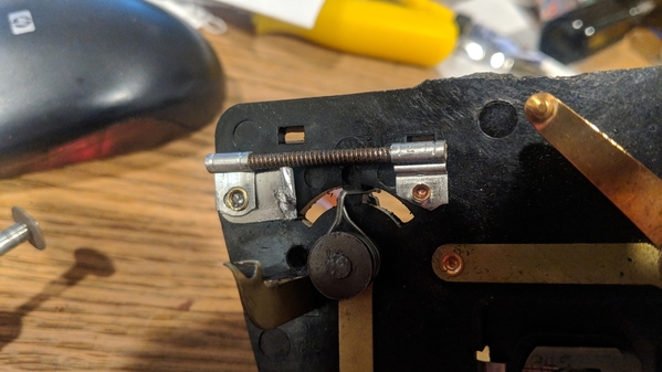
See the silver metal piece to the left? that is where the cathode of the diode will go, and that little brass tab with a hole, right next to the hole in the silver metal? that is where the anode will go. (this gives you a center rail positive dc pulse which I am told is most desirable.)
The silver piece of metal to the left again....remove it. You do not want to hurt the rivet that retains it up by the wirewound resistor, so notch it with a dremel and while holding the tab, rivet and plastic throttle plate with say , a close crescent wrench, back and forth it off until you get:

Now the last bit of prep...the compensating coil wire went up THRU this rivet, the silver inside is solder. using something, hog out the solder. I used a soldering pencil and a small screwdriver... to get:

Why do we do that? you are going to be reinserting the black wire from the compensating coil AND the cathode end of the diode.
Then since we removed the silver piece of metal, the diode sits down the side and we attach the anode to the brass tab, using the hole in it. Take a look at this to see orientation:

Please note, I am not the biggest fan of 'bare wires everywhere' so I cover the conductors in heat shrink. I even insulated the brass tab with the blue you see. Reattach any unsoldered wires and set the throttle plate back down over the straightened tabs and gently give the tabs a twist to retain it.
Nice, neat compact.
And lastly...

...swap out the power cord. These old lionel transformers are 50-60-70+ years old with aged, ozone attacked westinghouse rubberized heater cord. *anything* modern will do. I yank the cords off the electronics I dont fix and scrap out. note the molded in stop? Aint tying no knots in this cord.
once you get this far, clean, reassem and play choo choos.