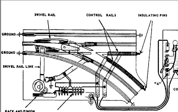
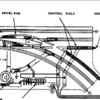
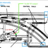
I have two diagrams from an O27 switch similar to yours, one unmodified, one has the modification you are working on.
Here is the unmodified switch
Here is the switch showing the modification you made
The modification pic depicts in red where you cut the wires. The green represents the wire you added and show in your pics connected to the "D" output of your ZW. As you can see in the pic, the wire you added feeds power to the two solenoid coils. Each coil requires a ground path back to a ZW "U" output (the ZW has four "U" outputs, also labeled COMMON, as shown in your pic) . Each coil's ground path is independently controlled by the controller shown on the right side of the pic. As depicted in the pic, pushing the controller arm up completes a ground path from the right coil, whereas pulling the controller arm down completes a ground path to the left coil. We have to get the ground of the O27 switch back to a ZW "U" output. Internal to the O27 switch, the two outer rails and one of the controller's connections are all connected together - thus whatever you connect to one outer rail of the O27 switch is fed to the other outer rail and the controller ground connection. So connecting one outer rail via the lockon shown in your pic to the a ZW "U" output will get ground to the switch controller. I indicated in Blue the O27 grounds that are internally connected together.
Hope I made things a bit clearer.


