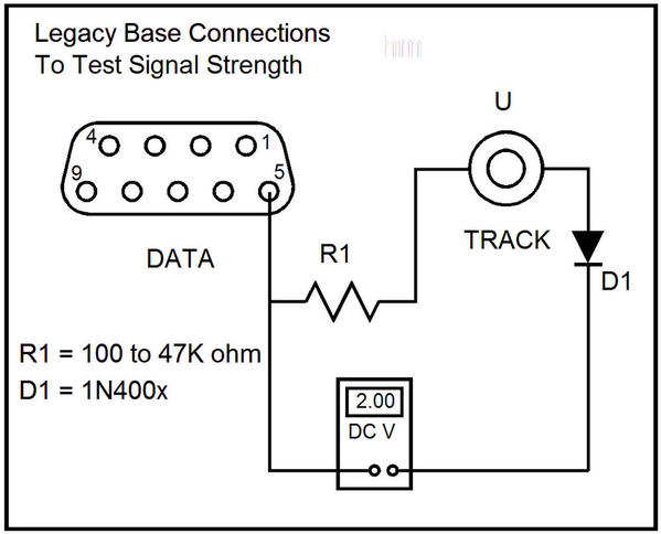
As part of my work with Lyle Dumont in Iowa to solve his TMCC signal problems, I developed an easy technique to measure the strength of the TMCC/Legacy signal going to the track (http://www.trainfacts.com/trainfacts/?p=436). 

Recently Lyle made some measurements on his 2 layouts that were very interesting.  First, he measured the Legacy base on his big layout (40'x90') without anything connected except the metering circuit connected to the Track stud and Pin 5 of the 9-pin.  He got about 1 volt, which is only half of what he should get for a good Base.  (Interestingly, when I visited Lyle over a year ago, his Legacy Base was defective, clipping off half of the sinewave Track signal.  He sent it to Lionel for repair, but now I doubt that it was ever really repaired since his voltage reading agrees with a half-clipped sinewave output.)

Lyle then connected the Track wire to the stud, and the signal dropped to about .3V.  We expect to see a lot of capacitive loading with a large layout and we don't have any numbers that determine go/no go for the Track signal.

Next, Lyle brought the Legacy Base from his smaller layout onto the big layout.  The unloaded reading was the full 2 volts that is expected, and the loading dropped things to about .63 volts, twice what the other Base was outputting.  He was able to run his balky steam engines without problems using the good Base.

Lyle was also able to make signal measurements on the smaller layout to confirm that he was getting a stronger Track signal, which was to be expected with the reduced capacitance of the smaller layout.

The moral of this story is that you can't beat having something that quantitatively measures the actual Track signal.  As a result, I am going back into the "TMCC/Legacy" accessories business by offering a complete metering unit that includes a volt/ohm meter, the rectifying circuit and the proper connectors (feed-thru 9-pin and forked lug) for attaching to a TMCC or Legacy Base.  The price is $60 plus shipping.  Contact me at dmanquen@msn.com for more details or to place an order.  Please do not try to order through this Forum.

Original Post

Replies sorted oldest to newest

I strongly recommend using a 1N914/1N4148 if available, but the 1N400x will work.  Other than that, the schematic is correct.

I would appreciate receiving results from anyone who uses this circuit so that we can build up a database.  Please measure unload voltage and voltage with Track wire attached.

Dale, I have found your website to be a great resource, and it saved my 1st impression of command.  Using the info on it I was able to retune a base and thus enjoy command on all my TMCC locomotives.  And I like that you are providing a way to measure the signal.  I have a question, will your kit be including a special type of meter?  I ask because I already have a couple Radio Shack and Harbor Freight specials, and thus wouldn't really need a new meter.  Have you thought of selling a version of the kit that uses the buyer's meter?

I've found two base outputs with weak signal outputs. I using a Tek scope, i find the same signals for healthy base outputs as shown above. I think the problem bases were something like a volt or less pp on the scope. Since this is apparently a more common than isolated incident, I wonder if the output device is being damaged by track shorts, etc.

And, if using a scope, what is the reason to include the diode Ingienero? Include it's drop?

Dale,


Using a Craftsman 82141 multimeter set a 2000mV, and through a 1N4004 diode, I read 1.4V unloaded, and 0.7V loaded (rounded). My layout has about 900 feet of track and 58 turnouts, and occupies a 33x38-ft room.


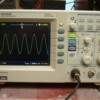
Then I used my Rigol oscilloscope, and had very interesting readings. I have the traces and was going to post them, but I am not sure if they are relevant.


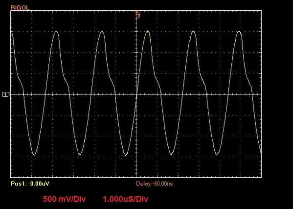
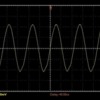
When connected across Pin-5 and Term-U directly, the unloaded peak-to-to peak signal has an amplitude of 6V, and it drops to 5.6V when loaded; the signals in both cases are clean, 2.2uS period or ~455KHz.


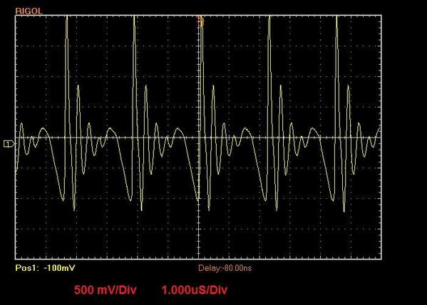
When the diode is in series with the scope and Term-U however, noise is introduced and while the peak-to-peak unloaded is still about 6V, the loaded drops to 2V p-p.


I then substituted the 1N4004 with a small, glass case signal diode (don't have the number) and the signal was clean throughout, but the amplitude I was getting made no sense, and then I could not get consistent traces, so I stopped.


Comments?


Alex

When I was touring around in 2012, I found a couple of Legacy Bases with clipped or distorted waveforms using my oscilloscope.  This is one reason why I am offering the Track signal meter.  If the signal is good, the unloaded reading is 2 volts, but a bad output reads around 1 volt - day and night difference. 


My personal Legacy Base is one that I got in "damaged" condition, and I repaired it.  I substituted a beefier output transistor than the original damaged one.


I am suspicious of nearby lightning strikes.  Maybe we should have a TVS directly at the Base output.

Dale, John -


Yes, a 10K resistor. Diode is 1N4004.


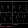
Here are the traces: [PLEASE, LOOK INSTEAD AT THE TRACES I POSTED FEB 4 AT 1:34PM]


Track not connected to base, scope connected to Pin-5 and U-Term (across 10K R) 

LegacySignal Unloaded no diode


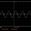
Track not connected to base, scope connected to Pin-5 and diode, which is in series with U-Term (10K R still in place, Pin-5 to U-Term)

LegacySignal Unloaded with diode


Track connected to Base U-Term, scope connected to Pin-5 and U-Term (across 10K R)

LegacySignal Loaded no diode


Track connected to Base U-Term, scope connected to Pin-5 and to diode, which is in series with U-Term (10K R still in place, Pin-5 to U-Term) 

LegacySignal Loaded with diode


These OK? Still want them emailed?


Alex

Attachments

Images (4)
  • LegacySignal Unloaded no diode
  • LegacySignal Unloaded with diode
  • LegacySignal Loaded no diode
  • LegacySignal Loaded with diode
Last edited by Ingeniero No1

Chuck,


[PLEASE, LOOK INSTEAD AT THE TRACES I POSTED FEB 4 AT 1:34PM]


Your are correct, and it was my mistake when I wrote 6V p-p. You see, the 6V p-p is what I read when I used the signal diode instead of the 1N4004. The amplitudes I was getting did not make sense, so I tried it several times, but the results kept varying, so I gave up on that test. However, when I wrote that post, I looked at the 'last' setting I had on the scope, and it was 1V/Div, which was correct when I was using the signal diode, but not for the 1N4004. I re-posted (below) the traces with the scope connected without the diode.


Dale,


I know what the diode is for, but I thought I would see how the signal looked on the scope with the diode in series with the U-Term; that is, between the scope and the U-Term - just as if the scope were the multimeter. The signal was distorted, and it is not what I expected, so I used a signal diode instead. With the signal diode the signal was not distorted, but the amplitude was about twice as it was with the 1N4004. I have not posted those traces.


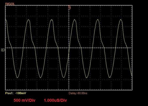
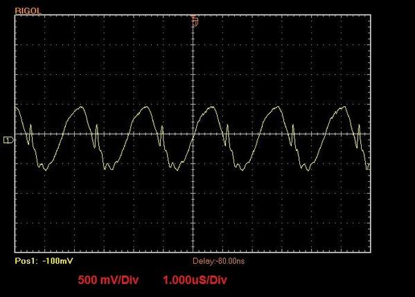
The signal is not distorted when the scope is connected directly to the U-Term and Pin-5 (with the resistor across Pin-5 and U-Term) whether the track is connected to the U-Term, as shown by these two traces. 


Track NOT connected to the base.

LegacySignal Unloaded no diode


Track connected to the base.

LegacySignal Loaded no diode


Sorry about the confusion.


Alex


Attachments

Images (2)
  • LegacySignal Unloaded no diode
  • LegacySignal Loaded no diode
Last edited by Ingeniero No1

I guessed that about the diode...to see what it looks like when it is included and what you might expect with it when you use just the multimeter.

Anyway, thank you Dale and Alex for addressing this problem, I had encountered it but put it aside.

I like the idea of the tester. 

Alex, I don't know how good your 'scope is, but when I view my unloaded Track signal, there is absolutely no distortion of the sinewave, with or without my metering circuit attached.  Your waveform has significant even-order distortion without anything attached.  That type of distortion won't do much to the FM signal, but it shouldn't be there.


My amplitude on my 'scope is 5V p-p, which is reasonable for a circuit that has a +5V power supply.


I just tested my first batch of five metering circuits, and they all indicate 1.95-1.99V on the meter.  The Base signal may be sagging slightly as the Base warms up.

Last edited by Dale Manquen

Ok. I did the Legacy base not connected and connected to the layout outside rail. I have a 1K across from the DB9 pin 5 and the U terminal. And the scope(s) connected across the 1K resistor (the 454A has a little trigger stab issue...sorry, but it's still informative). There is a little distortion in the second photo which has the base connected to the layout outside rail.

BaseOutput

BaseOutput2

Attachments

Images (2)
  • BaseOutput
  • BaseOutput2
Originally Posted by cjack:

Ok. I did the Legacy base not connected and connected to the layout outside rail. I have a 1K across from the DB9 pin 5 and the U terminal. And the scope(s) connected across the 1K resistor (the 454A has a little trigger stab issue...sorry, but it's still informative). There is a little distortion in the second photo which has the base connected to the layout outside rail.

Oh, both scopes are on 1vdc/cm and .5 uS/cm timebase

BaseOutput

BaseOutput2


I got it. In trying to keep the scope leads securely attached across the resistor, I had attached the ground clip to the U-Term and the probe to the Pin-5 side. Duh, this obviously does not properly capture the signal from the U-Term. 


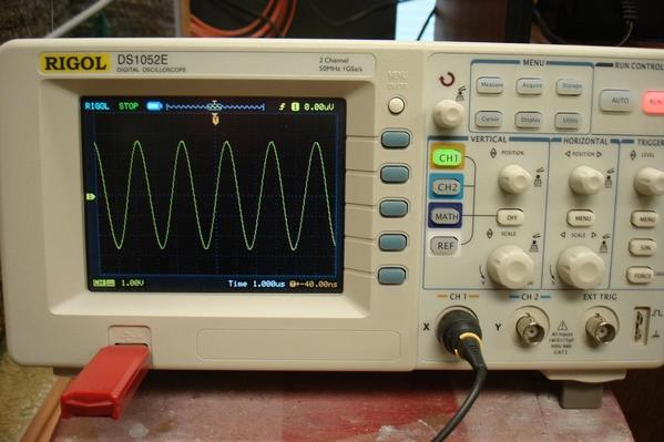
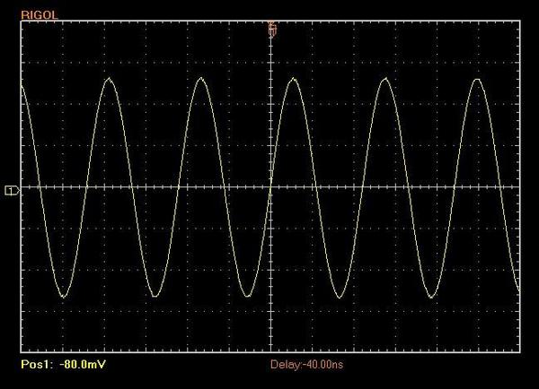
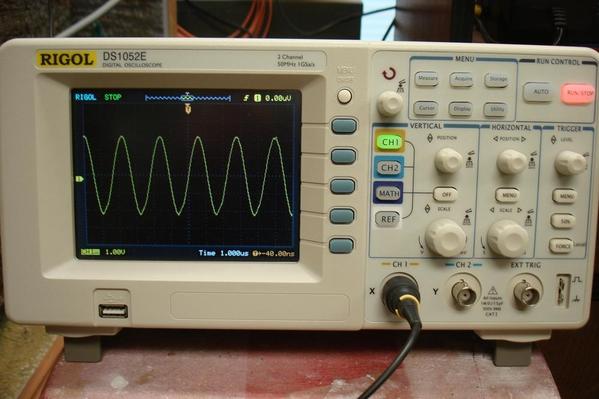
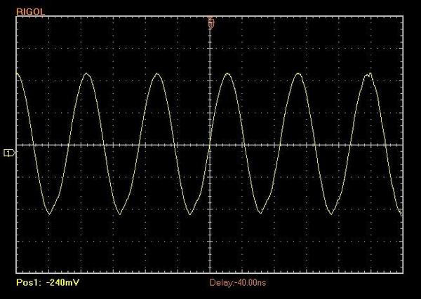
Anyway, by switching the connections; i.e., the scope ground clip to Pin-5 and the probe to the other side of the resistor, U-Term, I get the traces that 'Dale will like'!


Unloaded (track not connected) All below are 1.0V/Div and 1.000us/Div


LegacySig Unoaded PropConnSCOPE

LegacySignal Unloaded PropConn


Loaded (track connected)


LegacySig Loaded PropConnSCOPE

LegacySignal Loaded PropConn


I'm enjoying this . . . and thanks to all who are participating!


Alex

Attachments

Images (4)
  • LegacySig Unoaded PropConnSCOPE
  • LegacySignal Unloaded PropConn
  • LegacySig Loaded PropConnSCOPE
  • LegacySignal Loaded PropConn
Last edited by Ingeniero No1

Chuck and Alex, you get gold stars!  Can you give a description of your layouts to help us judge how hard the Base is working?


I wish I knew how much capacitance at the terminals would produce the same amount of distortion.  I don't think there are necessarily nonlinearities on the layout, but rather how the Base can drive positive vs. negative current into a large capacitor.  The Base output stage is a single-ended one-transistor stage.

The capacitance at the terminals of my layout is 0.1026uF as I just measured with a good LCR meter. It uses a 1KHz measuring signal. So about .1 microfarad measured with the base hooked up.

The layout is 12 by 14 ft, 3 big loops, 4ea 8 ft sidings, and a yard with say 20 feet of track if you stretched it out. 21 switches, all FasTrack.

Originally Posted by cjack:

The capacitance at the terminals of my layout is 0.1026uF as I just measured with a good LCR meter. It uses a 1KHz measuring signal. So about .1 microfarad measured with the base hooked up.

The layout is 12 by 14 ft, 3 big loops, 4ea 8 ft sidings, and a yard with say 20 feet of track if you stretched it out. 21 switches, all FasTrack.

I disconnected the base and the layout itself measures 0.0022uF. Not so much.

Seems like most of the hooked up capacitance was the output of the base.

Originally Posted by Dale Manquen:

Chuck and Alex, you get gold stars!  Can you give a description of your layouts to help us judge how hard the Base is working?


I wish I knew how much capacitance at the terminals would produce the same amount of distortion.  I don't think there are necessarily nonlinearities on the layout, but rather how the Base can drive positive vs. negative current into a large capacitor.  The Base output stage is a single-ended one-transistor stage.

One wonders if you couldn't add a booster stage to the command base.  Of course, I believe that's what you tried to do at NJ Hi-Railers, right?


Originally Posted by Dale Manquen:

I use a common digital VOM.  By including the meter, I know exactly what the user has, and that allows me to be very explicit with my instructions.  Read "turnkey"!

I will consider you suggestion for a meterless version.

Dale,


If you could, please consider a "Meterless" Version, as I have several Fluke and Simpson DVM's already.


Thank you in advance!

Originally Posted by Dale Manquen:

Chuck, do you have an "ground planing"?

You mean a ground plane under the track? I do have a single wire running around under the table connected to ground pin #5. Roughly about the perimeter of say 10 by 12. Probably about 4 inches below the plane of the track.

Not sure I remember why...I probably added it when I had all the issues with the SC-2s under the table. But that was solved with connecting COM on the SC-2s, (powered with a separate transformer), to the outside rail U terminal which I had not done initially.

The SC-2 is like an engine I began to see. It needs to be "on the track" just like an engine I think. Anyway, the SC-2s work flawlessly now and very fast for route switching.

Last edited by cjack

My layout room is 33 x 38 ft and the layout occupies most of it. I have about 900 feet of Atlas track, 46 Atlas turnouts, and 12 RCS turnouts. There are four levels altogether, but the dual mains run on two just two levels. If I were to 'unravel' the dual folded dog-bone and had Ø108 curves at each end, the dual track oval would be about 120 feet long.


I have two Z4000's supplying TIU-1 and a ZW-L supplying TIU-2. I have five AIU's to run some accessories and all the turnouts (some are crossover and are connected in parallel), and in addition I have run parallel wires to all the turnouts and can operate them from the control panel as well. 


Each of the four outputs from each TIU is connected to a terminal or relay block, and each block supplies power to six tracks, for a total of (2-TIU's * 4-Term/Rel blocks * 6-Tracks =) 48 blocks altogether. The Legacy base is connected to an outside rail on one of the mains next to the main control panel.


Everything runs very well, and I run up to four trains at a time, whether DCS or Legacy or both. Since just before Christmas we have had over 40 guests look at the layout, and I have run the trains many times 'for the guests' without any control problems, whether DCS or Legacy.


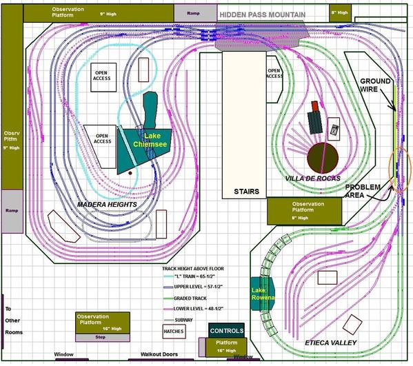
However, since Dale brought it up, in July 2012, when I first started using Legacy, I had a problem spot where the one or two Legacy engines I had at the time would simply shut down. I posted this thread here, and you guys gave me the solution. I ran a ground wire (about 8 feet long, under the upper level) as shown below, and problem solved. 


What I find interesting is that my mains run over each other many places, and for over 60 feet at one stretch, and yet, I had only one small problem area!


RODDAU 28 - Combined View 06B GrndPln


I hadn't received a gold star in a long time - Thank You, Dale!


Alex

Attachments

Images (1)
  • RODDAU 28 - Combined View 06B GrndPln
Last edited by Ingeniero No1

This all seems nice, but it is only a go no go on the Legacy or TMCC base, which in theory should be working fine.


Isn't the real issue determining the signal along the track, where all the variables are?


Didn't someone post earlier they build a receive to measure signal strength on the track, based off the R2LC radio receiver?   Isn't this what is really needed?  G

Originally Posted by GGG:

This all seems nice, but it is only a go no go on the Legacy or TMCC base, which in theory should be working fine.


Isn't the real issue determining the signal along the track, where all the variables are?


Didn't someone post earlier they build a receive to measure signal strength on the track, based off the R2LC radio receiver?   Isn't this what is really needed?  G

What you say is all true, but one needs to know the health of the source of the signal before investigating reception issues. I helped one forum guy who went in circles trying to improve reception, even sent the base back to Lionel who pronounced it fine. And it had a very small output...something like a half volt instead of 3 volts pp. Not dead, just weak. That was the source of all his problems. I advised him to send it back to Lionel and state what we found, which he did, and they fixed or replaced it. I just got a thank you email from him after a solid year of good running.  

Alex, what is the nature of the room construction - basement, attic, etc.?


An airborne signal detector would be the next step.  I have worked on that problem, but it is tough.  What do you use for a "standard" antenna?  How do you account for the variation from board to board in the R2LCs?


Another possible product is a "locomotive calibrator".  This would be a shielded test box with a variable TMCC signal that would allow the user to determine how sensitive his locomotive is to the TMCC track signal. 


Often it is hard to determine who is the culprit - Base, layout, locomotive or static in the environment due to faulty electrical devices.  My metering scheme is helpful with the first two links in this chain.

Originally Posted by Dale Manquen:

Alex, what is the nature of the room construction - basement, attic, etc.?


An airborne signal detector would be the next step.  I have worked on that problem, but it is tough.  What do you use for a "standard" antenna?  How do you account for the variation from board to board in the R2LCs?


Another possible product is a "locomotive calibrator".  This would be a shielded test box with a variable TMCC signal that would allow the user to determine how sensitive his locomotive is to the TMCC track signal. 


Often it is hard to determine who is the culprit - Base, layout, locomotive or static in the environment due to faulty electrical devices.  My metering scheme is helpful with the first two links in this chain.

You use the Lionel basic small antenna, then test how much variation antenna size makes.  Don't need to worry about the R2LC as long as you use one that seems average.

The point being precision isn't required.  You just need knowledge of a Satisfactory signal.


Chuck, to answer your question, I always like to trouble shoot something by jumping into a problem at the halfway point.  If I ran the in air receiver and had a good signal all around the layout I than know the base and the track and wiring are fine.  If I have a problem loco I know the loco is the issue.  I can swap the loco R2LC into the air tester and now I know if the R2LC is not sensitive enough.  Done.


I have had a few where the LCRX or the R2LC were the issues.  Even after trying to tune them.  Replace and the problem loco was fixed.


A few years ago I read an article from the RC helo guys.  Apparently the R2LC radio chip is the same.  They found in their application some of the resistor value where not sufficient, and the sensitivity of the chip was effected.  I always wondered if the same applies to the R2LC.   G

Dale,

Here are my results.

Without the Layout attached -

IMG_1055


And with the layout attached -


IMG_1056


The layout causes a slight distortion in the wave but it stays at 2.0 volts. I have 30 switches , about 300 feet of track and a multitude of control boards connected to the track.


I'm having fun doing this but I am not sure what it tells me other than my base signal's strength is good.   

Attachments

Images (2)
  • IMG_1055
  • IMG_1056
Last edited by Don M.

Dale wrote, in part:

"Alex, what is the nature of the room construction - basement, attic, etc.?"


It is in our 2300 Sq-Ft walk-out basement, Dale, of which the train room takes about 1250 Sq-Ft. The basement is concrete on three sides, stud wall & drywall on the fourth side, and I added stud walls and drywall to the bare concrete walls except for the back in the train room, which I just painted. I divided the basement and in addition to the train room it have a workshop, study, full bathroom, exercise room and utility room.


I did all the wiring myself also, and added several 20-amp circuits and outlets no more than 10-ft apart. It is a 9-ft pour, so I built the ceiling at 8-ft to use standard drywall. In addition to wiring in the walls, there is a lot of wiring above the dropped ceiling, so the basement is well surrounded with ground wires. I now suspect that this contributes to no issues with the Legacy anywhere in the room. The only problem is if I 'hide' the remote from the base, but when this happens I just hold the remote slightly higher and the problem is solved.


Thx.


Alex

Last edited by Ingeniero No1

Add Reply

Post

OGR Publishing, Inc., 1310 Eastside Centre Ct, Suite 6, Mountain Home, AR 72653
800-980-OGRR (6477)
www.ogaugerr.com

×
×
×
×
Link copied to your clipboard.
×
×