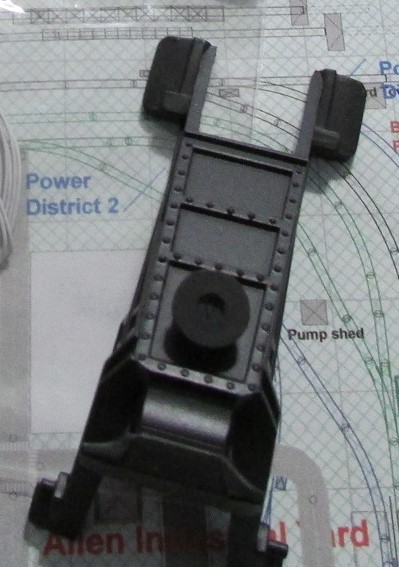
Just received the Lionel Gantry crane last night. I think it is going to work out well with the custom built crane.
Looks great Joe!!
Wonderful Joe! I am seeing all this great work and want to have stuff up now! LOL![]()
I purchased a cinder hoist a while back from Crescent Locomotive Works. Since it involves cutting a hole on the layout base plus modifying track I am going to tackle this project next on the entrance to the Allen Yard (the Timesaver module).
Crescent Locomotive makes an awesome looking hoist in which the spout moves up and down along with a bucket that starts at the bottom and can be raised to the top of the hoist.
Joe, that sure sounds interesting!! Cant wait to see it!![]()
The cinder hoist is in and looks pretty good if I do say so myself. It wasn't too hard to install.
A template comes with the hoist. The instruction sheet says how to place it.
I drew an outline with a black magic marker.
I cut the the sand mat out
Then drilled four holes in the corners big enough for my jig saw. Then I made a mess.
Next up was removing ties form the track that will go over the hoist pit. This is needed to make the track fit into the slot on the hoist.
The hoist is inserted into the hole
The track is placed into position
I use cork roadbed so I needed to place some under the hoist to make everything look good.
This is one beautiful cinder hoist.
Joe
Attachments
Very interesting Joe, I will b e fallowing along to see how this goes! Looks fun!![]()
Was thinking on how to identify turnouts other than placing stickers on the machine or the lights and came up with a modification of a sign post I made for a customer a few years ago. Those were rectangular and identified mainlines and sidings (N, E, S, W) for the customer.
I just bought a disc punch from Ebay which can make discs from 1/8 to 1/2 inch ( I have one that will go from 1/2 to 1 inch that is in transit). I punched 1/2 inch discs, printed the decal using Avery Clear mailing labels and mounted them on a U-Post I bought from Innovative Hobbies (Ultra Sign Posts).
I really like these U-posts. I have a line of sign posts on my web site. I have been using 100 mil sq styrene but am going to switch over to these posts.
Joe
Attachments
Joe, that's very clever! what program do you use for printing and how do you go about it?![]()
Mike:
Nothing exotic - I use Open Office Presentation (free clone of MicroSoft Presentation) to make the drawing. Simple circle / bar and text. I can post a PDF if you want later today. Just copy and paste into your presentation or drawing software and I think you can resize to what you want.
Joe
Hi Joe, that would be great! I can check it out after I get home from work!![]()
Mike:
I posted 3 files
1 - PDF
2 - Open Office Presentation
3 - Microsoft office Presentation (hopefully this will work)
I realized that with the pdf you can not change any text or numbers. Hopefully one of the other files will work.
Attachments
Thanks Joe! I was able to open the ppt. file and the pdf file. The odp only opened it MS Office!
Can you tell me where to get the free Office Presentation?
mike g. posted:Thanks Joe! I was able to open the ppt. file and the pdf file. The odp only opened it MS Office!
Can you tell me where to get the free Office Presentation?
I call it Open Office from force of habit but it is Libre. Open Office was the original but Libre is a better quality software.
mike g. posted:Thanks Joe! I was able to open the ppt. file and the pdf file. The odp only opened it MS Office!
Can you tell me where to get the free Office Presentation?
Mike, if you have Microsoft PowerPoint, you don't need Open Office. PowerPoint is also useful in making graphics for printing images to mount on thin board for buildings, walls and such. Former forum member Lee Willis introduced some nice uses of the graphics tools in PowerPoint.
Joe,
You are really making headway after solving the 4-way switch wiring issue. I appreciate the effort in switch ID and position awareness.
Hi Carl, I just checked and I do have Power point, I guess I will have to spend some time and play with it!![]()
Thanks for the link Joe! I guess I don't need it as I just found out I have Power Point already! LOL![]()
Did a little more work today.
I connected power and ground to the gantry crane. I soldered wire to two Ross pins then ran one outside rail to ground and the other to a toggle switch on the control board. I programmed the crane as accessory 1. To rotate the crane one selects ACC 1 and uses the red throttle knob on the Legacy remote. To move the crane along the track select '2' on ACC and use the red knob. To move the 'hook' up or down use the boost button. To turn the magnet on and off use the brake button. It takes some getting use to but this accessory is going to be a lot of fun.
I also changed around the position of my gantry crane. Last post I had the crane straddling the Gargraves track. I changed it so the crane now rides on one Gargraves rail and on its own track on the opposite side. The reult is a lot more room on the one side for crates.
I wired track out to the main line - finally - (where the UP caboose is)
I also tried a new approach for power for my custom built bumpers on Ross track. I have been soldering the lamp wire to Atlas O rail joiners and using them upside down on the Ross / Gargraves track but the rail joiners interfered with proper seating of the bumper plus the joiners were very loose. So I soldered the wire to Ross track pins. The fit of the track pins is a lot tighter but they do stick out a little.
Next week it is the approach track to the double crossover then the real fun begins.............
Joe
Attachments
I just purchased a little Lionel yard shack that has crane sounds. It is supposed to act in concert with the movements of the crane. Lionel also has a small shed that has steel mill sounds. I am not sure if both are the same sounds or not.
Did some more work on the layout. I have one main line section that goes up to 1 inch then back down again on a 2% grade. I first laid down the track then using a magic marker traced out the edges.
I then removed the track and installed Woodland Scenics foam risers using hot glue.
I used pink foam for the straight sections since it is less expensive then the Woodland Scenics foam.
Next W/E I am going to cut since foam walls I bought from Scenic Express a few years back and glue them to the pink foam. Woodland Scenics plaster cloth will go every where else.
I am thinking about using foam to raise the area behind the track and the wall with the window to 2 inches, install some industrial flats and track. The track won't get any power but I can park box cars there.
Attachments
Nice progress Joe!
Joe, you sure have been busy! Things are looking great! I like how you traced out your track for the road bed, nice idea! I know I will be using it in the future! Thanks for sharing!![]()
Have not done much. Things went down hill real fast with my back - upshot lower back surgery on Nov 20 (T12 down to L5). Never did anything in a small way...............
I am filling in some space in the back. My plan is an elevated section with an industrial building front (got a bunch of old Korber flats) plus a straight track not connected to the layout. I figure it would be a good place to store box cars rather then in a closet. I have enough room for a 3 inch side wall, docks plus the track.
Attachments
I'm back (no pun intended). Surgery was Nov 22. It took a bit to get into shape enough to start bending over the layout. Fortunately doc only needed to scrape bone on all 6 discs. My legs don't hurt anymore and that is a blessing.
I am trying something new for me on an elevated section of the layout. Jury is till out on how it will look. I had some Woodland Scenics vinyl sand mats left over so cut them into sections to lay over the foam inclines. I used a heat gun to bend the mat into place then hot glue on the edges to glue into place. I went over the edges with the heat gun again to remelt and flatten any rough sections. There is a seam I need to cover up. The plan is to place cork roadbed then ballast. Hopefully more sand over the seams plus scenery will work.
Guess we will see what happens
Joe
Attachments
Joe, Welcome back!! I'm glad you got relief, but that sounds nasty what the doctor had to do. I only have one bulging disc, but it is pressing on the sciatic nerve. The doctor hopes a steroid shot will cause the disc to not bulge as much and get off that nerve. We will see.
As to the layout, I think the vinyl sand mats looks great covering the foam risers. So far, so good I would say!
Hi Joe, I am with Mark! I think they look great! nice and easy to use with the inclines, who could complain. ![]()
I hope your recovery for your back goes smoothly! Take it easy and don't rush things!![]()
Thanks guys
I was getting epidural shots. They work great until they stop working (that's why the surgery). I still get them - once every three months for my neck which affects my right arm.
I had some sand I purchased from Hobby Lobby a while back. I spread wallboard putty over the seam in a small section and poured the sand over it. It worked good except the sand is the wrong color. I have an email into Woodland Scenics asking if there is a fine ballast or some other product that has the same color as the sand mats.
Joe
Did a little work on the layout - actually backwards. As shown below my original intent was to glue the Woodland Scenics vinyl mats across the foam risers.
It was a neat idea that did not work out. No matter how hard I tried to glue the mat down it was always loose. Screwing the track down through the track bed and the foam risers will not work unless I could find #4 screws over 1 1/2 inch long. Plus I found out when placing the track bed the risers were too narrow (so much for planning ahead).
So I removed the vinyl, cut some pink foam and glued it to the sides of the risers. I then used a wire foam cutter to bring the pink foam down roughly to the height of the riser. By the way lay some painters blue tape on the riser when using the foam wire cutter otherwise the wire will go right through the foam riser. I finished off by hand sanding with 60 grit paper to smooth everything out.
I also cut away some of the vinyl mat on both sides of the riser (not shown below). I will tape in some paper next week to create an 'embankment' then try plaster cloth.
Attachments
Finally did some more work. I am going to try plaster cloth. I spent the last few weeks setting up for it. I found that if I spread foam glue between the paper and the risers it holds the paper better while I use tape.
I have come to the conclusion I don't know what I am doing but I am having fun not knowing...........
Attachments
Finally bit the bullet and applied plaster cloth. I started out by cutting the cloth wide enough to just cover the top of the incline then went back with more cloth to cover the sides. I will have to do some sanding where the track bed will go before I paint.
Attachments
finally got back to laying track and promptly ran into a proble hopefully some one can help with. fist the update then the problem.
I laid all the track from the start of the incline all the way to the back of the layout at the end of the incline. As you can see I have feeder wires every where - probably overkill but I sure don't want to find 'dead spots' down the road. I usually use split jaw connectors but did not want to drill through the plaster cloth and foam inclines so I am going back to the rail joiner method for this portion of track.
Now the problem - I usually simply screw the track through the road bed to the plywood using Atlas O track screws. I even bought some longer 1 in screws from ACE. However these are not long enough. The screw will not hold down the track and road bed on the plaster cloth / foam incline (figure about 1.5 inches). I have foam tack glue I can use don the road bed to plaster cloth but what about the track????????????? ALL SUGGESTIONS WELCOMED!
What ever method is recommended I will try drilling the hole for the screws and filling with super glue then using the screws.
Joe
Attachments
Some progress
I ran an experiment. I know Woodland Scenics foam tack glue will work on cork roadbed to the plaster cloth but I was not sure about Atlas O plastic ties to the cork. Fortunately I also have Mod Podge Matte I use for other purposes. So I glued some spare track down to scrap pieces of cork, let it dry overnight under weight. The next day I tried peeling the track from the cork. That glued with foam tack glue came right up. That glued with the Mod Podge stayed put.
I have glued down some road bed and will keep working on it. The track is not glued down. I used it to align the road bed especially on the curves. At first I stuck Woodland Scenics foam tack pins through the roadbed and into the plaster cloth so the roadbed would not move. Then I placed the weights on the track. After about an hour or so I move on to the next set of road bed.
I am using MidWest cork. I like this stuff. It stays pliable even after paint. I don't remember the other brand I used but it turned so stiff after paint that it would break when one tried to use it on a curve.
Joe
Attachments
All the cork has been glued down to the plaster cloth. I have just started gluing the track to the cloth using the Mod Podge. I also dripped some super glue on a track screw and drove it into the foam. I'm not too sure how this is going to go.
I thought about dropping in ballast while the glue under the track was wet but decided against it since the track is fairly loose and needed to be weighted down as soon as possible.
Once I finish gluing track U will be going back to wiring. I have three independent power districts each with its own power brick and powermaster (I am only running Legacy). The basic wire scheme consists of running power and ground from each power brick through the powermaster. The grounds from the three powermasters are connected to one terminal. From there I have wires running to various terminals under the layout. In effect all track has a common ground. Power goes from each powermaster to its own terminal board. Power is then routed to other terminal boards within each power district. For spurs I want to control power to I run power to a toggle switch on a control board to a dedicated terminal then to the track. It's overkill but I am using 10 watt SPST toggle switches.
Attachments
Finally got run some trains in a circle - for me an event!
I will start wiring for the inside loop next week. This is mostly Atlas O track so I am reserving the Splitjaws for this track. I bought some Ross pins / pigtails and spent the afternoon soldering extension wires on them. These will be used for the various yards where Ross track governs.
The white wires on the track are for non-derail of Ross turnouts.
Took an aside and photographed a small diorama I have on the layout. This is a scrap yard sort of. I purchased a Lionel tool shed that has a crane sound package inside. I also bought a couple of Preiser packaged figures I will place in the diorama. The gantry crane is a Lionel command control. I thought I was not much on motorized accessories but this crane is a bunch of fun to run and it works/looks great on the Gargraves gantry track! The traveling crane, wood water tower, maintenance shed and inspection stand are my designs.
Attachments
Looks like a good plan Joe!
Remember that old saying "if it ain't broke don't fix it". Well I decided to fix it. There are some O54 Atlas O turnouts is hard to get areas so I decided to replace them with Ross O54. Only I forgot that Atlas O are 22.5 degrees and Ross O54's are 30 degrees. So out went all the Atlas O O54 curves - I could recover by using two 1/3 O81's but decided against it. I also did screw up and ordered a O64 Ross turnout which turned out to be fortunate since it is a 22.5 allowing me to use Atlas O stock.
I did some reconnoitering and came up with a fix that involves no new purchases and also solves an issue I had with a siding (no way to bring in or remove cars - I wanted a resident locomotive there). I put the Atlas O turnout back where it belongs and am using the three Ross turnouts in the siding are to the left. Down the road I will start replacing the Atlas O switch motors with Z-Stuff DZ1000's. This way one isolated rail and one wire will control non-derail.
Attachments
I wired in one siding over the weekend that consisted of all Ross track. I used something new for me to connect track power and ground. Not sure if these are Gargraves or Ross product. They are track pins with wires soldered to the bottom. The jury is still out on these. If the pins are pushed too hard into the rails the solder joints shear and break. If one pulls too hard on the wires after installation some of the joints fail. However once installed since the wires go straight down they are almost impossible to see.
I also place these pins at the ends of the spur where they excel. I can also attach the bumper lights to the pins. I will hide the wires later with ballast and scenery.
Attachments
I have tried some of those pins with jumpers soldered and have had the same experience. If you don’t manhandle them, they seem like they will be quite reliable. Mine came in packages with GarGraves name and logo.
No problem with these GarGraves pins. I used them for my layout and have had zero trouble with them.
Thanks guys - I was a little worried about longevity.
Joe Fauty posted:Thanks guys - I was a little worried about longevity.
About the pins, I hope. ![]()
Richie C. posted:Joe Fauty posted:Thanks guys - I was a little worried about longevity.
About the pins, I hope.
LOL
Mark Boyce posted:Richie C. posted:Joe Fauty posted:Thanks guys - I was a little worried about longevity.
About the pins, I hope.
LOL
The pins the pins!!!!
Well - no good plan goes unpunished. I have to decided to move. Will be having a home built so the model RR layout is now defunct to be re-built starting in about 6 months..................
Do you plan to move what you have built, or start over? Either way, I'll look forward to seeing the building start up again!
Mark:
I will be starting over. The new train room will be narrower but longer.
Thanks for staying with me in this.
Joe
Yes that makes sense with a different size room. Sure I'll stay with you on it. A similar thing happened to me, except a different room was allocated to me by my wife. I had no problem, as the room is larger than the first very small room.
As it turned out I did not move so it is back to the existing layout!
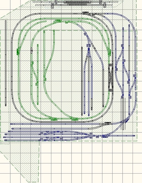
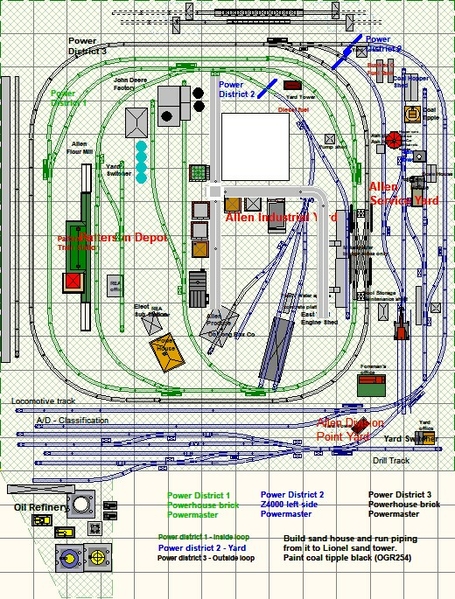
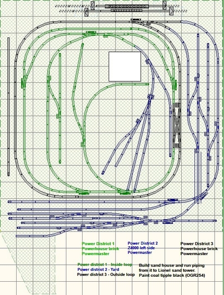
I made some design changes
I added a spur at the bottom which will go into a refinery yard. I also opened up the middle of the layout to allow for more buildings.
Attachments
Joe, It sounds good that you can move forward with this layout. We have moved too many times to suit me.
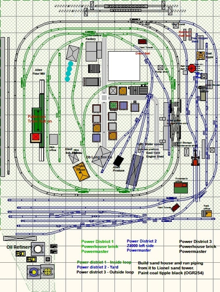
Finally got the track placed - still need to wire four studs but at least the track is down. I deviated from the plans I posted earlier. I ended up curving one track into the back end of a little town. I hope to set up some track side businesses with road work on the other side.
The new design looks like below. I hope to have all track wired next Sunday.
Attachments
Wow, Joe! Once you get moving you really get a lot done. I hope you get the wiring done by Sunday. I never seem to come close to any goals, so I just do things as I have time!
Finally finished wiring power to tracks - only took 2 years! (I have only Sunday afternoon to work on it). I will clean track then run a locomotive around to make sure I have adequate voltage in all sections. If I need to add wire I will most likely solder power (middle rail) in those spots since I use a 'double ground' (both outside tracks) every where.
One advantage to being slow is that I ended up trying different methods of attaching wire to track. I started out using the Atlas O wired connectors (see below) then discovered split jaw connectors. These are iron clad once connected but you need to be very precise where drilling the holes as there is a crimp connect that needs to sit straight down into the hole. when I started using Ross track I tried the wired connecting pins but soon discarded them. Two issues - if I inserted the track too tight I sheared the solder joint and if I pulled too hard when running the wire under the table I pulled the wire off the connecting pin. For the last series of connections I reverted to the tried and true method of soldering wire to the track rails. among other things I could solder the track on a bench, insert it on the table then drill holes where ever I wanted them.
In the end I would say soldering followed by the Atlas O connectors were the way to go.
Atlas O soldered rail connectors
Split Jaw Connectors - originally developed for outdoor G scale track. As you can see the location for the hole for each crimp connect has to be precisely drilled
I have 13 spurs that are connected to toggle switches - next up is to make some lighted bumpers so I can tell when the track power is on.
I bought a bunch of Lionel bumpers a few years back and am using those for now. I did have a few of the lighted bumpers but discovered the bulbs were rated at 12 volts which is incompatible with the 18 volt track voltage so I bought 18 volt red lights (Circuit Concepts - see photo) and depending on which track Ross or Atlas O soldered the wires to the appropriate connectors and attached them to the track ends. I have designed both wood and plastic and built my own track bumpers which eventually I will replace for the Lionel.
Lionel bumper with the Circuit Concepts light. I had to drill a larger hole on top so glued a Plastruct SX-4 which stops the bulb from falling through the hole. I solder the wires to the appropriate connectors while installed in the bumper.
This a the wood bumper design. There are two posts in the back that fit between the track ties that hold it in place. this design would be no good for Fastrack.
This is the plastic version. You can see the two pins that are inserted into the Ross track.
Attachments
All Spurs now have power indicator lights (aka lighted bumpers).
I had Lionel lighted bumpers however the bulbs were rated at 12 volts which to me made no sense since typical command control track voltage is 18 volts. I popped out the light sockets from these bumpers and bought more unlighted bumpers at a swap meet a while back. I painted all the bumpers black.
Next I found 18V red lights from Cir-Kit Concepts
To make these work in the bumpers I drilled a hole in the top to fit a Plastruct SX-4 'stand' and glued it in upside down.
Since I use both Atlas O and Ross track I needed to solder the leads for the lights to the appropriate terminal joiners. To start the process I threaded each light through the top of the bumper, added electrical tape on the bottom to hold the light in place and cut the leads to length.
Once that was done I soldered the leads to the appropriate terminal joiner.
The leads for each bumper were attached to the ends of the spur tracks.
Next week I start wiring turnout switch motors. I am using both Atlas O and Ross turnouts. Where I have Ross turnouts I will wire non-derail. I have both Z-Stuff DZ-1100R detectors (which when black tape is placed over the IR sensor can be used as an position indicator) and MTH dwarf signals I will be using to indicate turnout position. These indicators will be connected to the switch motors through two different relays I have - Z-Stuff DZ-1008 electronic and Atlas O 200 electro-mechanical.
All turnouts are powered with a Lionel CW-80 transformer. At first I had the turnouts powered through the programmed accessory port. I started out with all DZ-1008 relays but kept blowing them up. I found out from a friend with a fast oscilloscope that at transformer turn on the accessory port spiked to 32 volts before settling down the the programmed voltage. The DZ-1008 relays rated for 25 volts kept blowing up. This is when I started buying the Atlas O relay. I have also switched the power connection to the handle of the CW-80 so now I turn on the transformer with the handle in the off position then raise the handle to the desired voltage thereby bypassing the issue of the voltage spike.
I have all the turnout motors connected through momentary toggle switches to power. Yea I am one of those guys who uses 10 amp toggle switches for both spur power and turnouts. I really like the size - they are big and easy to handle. To protect the Atlas O relays from burnout I use a diode in line with the power connection to the relay. Note the diode will not work with the DZ-1008 due to internal electronics.
Bottom line as turnout 'things' wear out or blow up and get replaced I will be using the following - (kind a like 'if I knew then what I know now".........)
Ross Turnouts - DZ-1000 motors
Atlas O 200 relays
DZ-1100R detectors
DZ-1000 motors as replacements for Atlas O switch motors until the turnout goes south then Ross as a replacement.
Attachments
Started wiring turnouts. I have two types of turnout machines on the layout - Ross and Atlas O so have both DZ-1000 and Atlas O switch machines. I have all switch machines connected to momentary toggle switches (center connected to track ground). All switch machines must be connected to track ground to make the non-derail function work for the DZ-1000 motors.
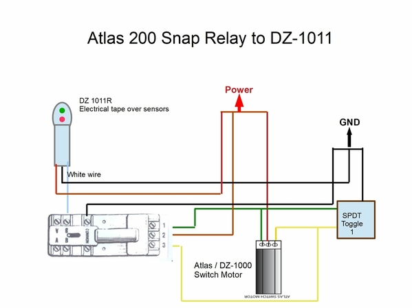
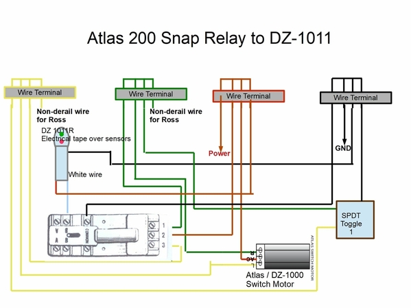
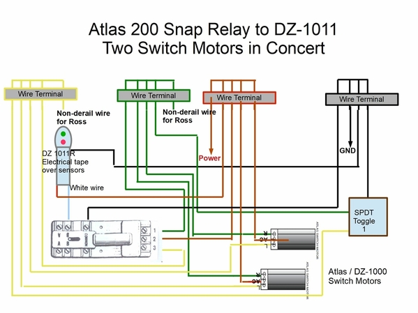
Right now I am wiring the switch machine with DZ-1011R detectors (electrical tape over sensor) and Atlas O 200 snap relays. The switch motor controls the position of the snap relay which controls the red/green position of the DZ-1011R's. While the LEDs on the Ross motors are momentary the DZ-1011R lights are 'constant on' so they indicate which position the turnout is in.
The diagrams below show the wiring schematic for this set up.
Above is the overview of needed connections
Above shows interconnections to European style terminals under the layout. The snap relay will also be under the table.
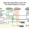
This diagram is for controlling two switches whose position will always be in tandem. Only one relay and detector are needed.
Attachments
Below are photos showing the process of connecting a DZ-1000 switch motor to a DZ-1011R detector and Atlas O 200 snap relay.
Below shows the European connectors. I used 20 / 22 gauge wire and wire ferrules from Ferrules Direct
DZ-1000 connected to 22 gauge ferrules
I used a crimp splice to extend the switch motor wires. I crimped the 22 gauge into an 18 gauge ferrule then crimped the assembly into the splice connect.
This is a shot of the complete circuit for one turnout under the table. The red / white / black wires on the right are from the DZ-1011R.
Success - sort of. The detector is green however it should be red. easy switch of wire connection the the Atlas O snap relay.
Attachments
@Joe Fauty posted:Since a forum member expressed interest in the split jaw connectors I thought I would add a little more info on how I make connections to them. the spilt jaw connectors come with a ring crimp connect. The normal method is to crimp a wire into the ring connect then attach the connect to the jaws. I want to make absolutely sure the wire never slips out of the crimp connect so I use ferrules. I first crimp the wire into the ferrule then I crimp the ferrule into the ring connect. Using this method the wire is not going anywhere.
Also if anyone is interested in building their own bumpers from wood or plastic see the attached file. If I install lights into the bumpers I use a Plastruct SX-4 flange upside down. I drill a hole to fit the top of the flange then glue it in place. The light bulb fits nicely inside the flange.
Joe,
Thanks for posting this. I have always had trouble keeping wires connected to Split Jaws. Now I know the solution.
NH Joe
Joe, Very nice progress!
Would you know if the split jaw connectors still made for O gauge track?
NHJoe - you are welcome sir!
EMD - it has been a while but starting info is below
Splitjaw Products, Inc
The guy to talk to is Jerry.
Power Supply Connectors (Standard)
SKU B-250-PSC-5.0
Weight 0.02lbs
Material: Brass
Code: 250 - 5.0mm
Type: 16-14 Gauge
Note - if you use Gargraves track because of the flange at the bottom the clamps are too shallow to fit properly. I am not sure if Jerry has modified any clamps to fit Gargraves since that was two years ago. The standard clamp will fit Ross track perfectly. If you are using Atlas O track Jerry will need to shave off about 1/32 from each piece so they will fit. He has done this for me and other people so it won't be an issue.
I am still wiring turnout switch motors. I had issues with two Atlas O switch machines which kept me scratching my head for a few Sundays. They would work by themselves but as soon as I placed the DZ-101R detector and Atlas 200 snap relay in the circuit the switch motor either became very sluggish or stopped working. This is with a Lionel ZW at 20 volts so plenty of current and voltage.
I set up a bench test to make sure the snap relays and detectors were functioning properly which they were. I used an extra Atlas wye turnout as my test vehicle for the bench testing. Once I determined a set of DZ-1011R / snap relay worked on the bench I wired them back into place on the layout but disconnected the turnout switch motors. The snap relays and detectors worked just fine by them selves. Next I connected the switch motor wires to thew the wye to make sure I was electrically sound. With the wye wired in place of the curved turnouts every thing worked great. So it turned out to be the Atlas O switch machines - what the issue is I don't know but now I am replacing them with DZ-1000 motors. Next Sunday I will be able to determine whether the DZ-1000, DZ-1011R, Atlas 200 snap relay work.
I had time this morning so wired DZ-1000's in place of the Atlas O switch machines. Ever thing worked fine. Again I do not know what is wrong with the Atlas O machines since they work when they alone are connected to power but not when the Atlas 200 snap relay and DZ-10011R are in the circuit.
Below are photos of a DZ-1000 in place connected to an Atlas turnout. I did have to carve out a small section of cork roadbed under the throw bar otherwise it interfered with the switching. I will need to pay attention when it becomes time for ballast that I do not fill up the hole in the cork roadbed.
Attachments
I wired my first DZ-1000 / Ross turnout for non-derail. It was as easy as isolating a section of ground track just before the turnout, soldering a wire to the track and running that wire to the appropriate side of the DZ-1000. worked like a charm.
I will use the non-derail as a back up for turnouts I can't readily reach.
Joe
Ran into something new setting up non-derail on one switch. I test the function by rolling a car over the insulated track (by the way if the switch machines are connected to the same ground as the track then track power does not need to be on to test the non-derail function). On both sides the car wheels kept sparking when passing from one track section to the insulated track. My first thought was dirty tracks from soldering the non-derail wire in place. I cleaned both and the problem went away on one side. The other side kept sparking. After some head scratching I noticed the two tracks were slightly off in alignment. I fixed the alignment and no more sparks. Crazy thing this was not a major alignment issue. I added an extra screw to make sure the track did not move again.
Sparks!? Whoa....watch out for those transient voltage spikes. I had to have a TIU repaired due to these after one to many derailments; even with TVS diodes installed. And yep....put in fresh diodes right away. Luckily the engines were not affected.
Still busy wiring turnouts. I learned something new today. One can not wire a Ross turnout using a DZ1000 motor for non -derail if an Atlas O 200 snap relay is used to control a dwarf signal indicating turnout position. Once a car passes over the isolated track that triggers the relay, the relay stays 'on' until the connection is broken. If if the car sits on the isolated track or say there is a long consist the relay will stay on until it burns out; which takes no time at all. To make this work a DZ1008 needs to be substituted in for the 200 snap relay.
Joe
I have a bunch of those Snap-Relays, and I notice they're just like Atlas switch motors, so I assumed they'd go up in flames like the Atlas switch motor with more than a few seconds of power. ![]()
I'm using the DZ-2500, so I'll just use their non-derailing lines. ![]()
John:
You are correct the 200 is just a miniature version of their motor but set up like a DPDT relay. It did not take long for the relay to freeze up. I should have known better with my experience with the switch motors. I am slowly changing out my Atlas switch motors with DZ1000 motors as the Atlas motors die - however when they work they work great. Most of the time the turnout points start to move real slow and don't complete the switch over to opposite rail. I disconnect the motor from the turnout and it works fine so I assume position wrt to the turnout is critical with these devices. I have zero issues with the turnout itself. These turnouts are quality product.
For the time being I am going to switch out the 200 relays with DZ1008 relays where ever I have non-derail set up on DZ1000 motors.
It has been a while since I posted. The inside of my home is undergoing complete renovation - new tile and cabinets throughout, fireplace makeover with stone and a nice tiled in shower. The stuff I had was 15 years old and looked like sub par quality. Anyway the furniture is piled up in the garage and there are about 1M boxes stored in the various bedrooms.
I was able to get into the train room for some today. As mentioned in the previous post I am replacing Atlas snap relays with DZ-1008's wherever I have Ross turnouts with DZ-1000 motors and non-derail wires attached. I did three today an d the results turned out real good. There are two major issues in using the Atlas snap relays in non-derail-
1. (I know why for this) - when a car passes over the isolated rail the relay will work fine but the problem is if there are a whole bunch of cars passing over the isolated rail. Then the relay keeps being activated till it heats up and melts plastic.
2. (I don't know the reason for this) - with the snap relay in the circuit as a car passes over the isolated track the wheels spark like crazy. Track power and turnout motor power are separate however the grounds are all tied together. Once I switch in the DZ-1008 the sparking disappears. I am still scratching my head over this one.........
So my plan is this:
I have a mixture of Atlas turnouts with Atlas O motors, Ross turnouts with DZ-1000 motors and Atlas O turnouts with DZ-1000 motors. I will use the Atlas snap relay with all Atlas turnouts/motors and the 1008 relay with all Ross and Atlas turnouts with DZ-1000 motors. I have DZ-1011R detector/lights connected to both Atlas snap relays and DZ-1008's to indicate turnout position with no issues. I have some MTH dwarf signals I am going to try also. There should be no issue using them with either the snap relay nor the 1008's.
No mystery with the Atlas Snap Relays, they are limited duty devices just like the Atlas dual-coil switch machines. Leave them energized for more than a few seconds and they're a puddle of plastic! The DZ-1008 relay is a continuous duty relay, you can leave it energized all day.
@gunrunnerjohn posted:No mystery with the Atlas Snap Relays, they are limited duty devices just like the Atlas dual-coil switch machines. Leave them energized for more than a few seconds and they're a puddle of plastic! The DZ-1008 relay is a continuous duty relay, you can leave it energized all day.
John:
How do you plan to power your turnouts and are you using any kind of position indicator?
Joe
Joe, my switches all have the DZ-2500 switch machine, so they have position indication built in, and I'll be bringing the line back to a control panel for a visual look at the layout and the switch status. Each DZ-2500 also has a red & green LED to indicate the path. If the "out" path is your "main" path, you can also switch the sense of the LED's so the green is active for the "out" path. Finally, the DZ-2500 are command controlled, so I'll have control of all the switches from the TMCC or Legacy remote.
@gunrunnerjohn posted:Joe, my switches all have the DZ-2500 switch machine, so they have position indication built in, and I'll be bringing the line back to a control panel for a visual look at the layout and the switch status. Each DZ-2500 also has a red & green LED to indicate the path. If the "out" path is your "main" path, you can also switch the sense of the LED's so the green is active for the "out" path. Finally, the DZ-2500 are command controlled, so I'll have control of all the switches from the TMCC or Legacy remote.
Thanks John - I would be interested in knowing how the 2500's act as you start using them.
You're not the only one that's very interested in how the DZ-2500's play when I get them all wired! ![]()
![]()
Spent the day changing out Atlas O switch machines for Z-Stuff DZ-1000's. There was only one Atlas machine that was not functioning but I ended up replacing three. I have only 2 Atlas machines left but they are at the edge of the train board and are working so I will leave them connected till they stop working. When I started out replacing the Atlas O switch machines with DZ-1000s I could not find any relevant info on how to set up the DZ-1000 for proper functioning other than finding out the eye of the 1000 control arm is supposed to be parallel to and 1/2 inch from the eye Atlas O switch rod so I ended up writing a little tutorial on what I learned and submitted it to OGR for possible publishing. The most important thing is to notch the roadbed under the Atlas O switch rod if you are using it otherwise the roadbed interferes with the spring pin and prevents it from closing the turnout point rails. You can see the notch I cut below.
Attachments
I think I have determined there is a basic electrical incompatibility between Atlas O 200 snap relays and DZ-1000 motors. I was using the relays to power a DZ-1011R detector (tape over the IR detector) to indicate turnout position. Like the DZ1000 the center post on the 200 is connected to power. However the L and R posts of the DZ1000 go to common while it appears the L and R posts of the 200 go to power. I connected these wires between the DZ1000 and 200 so that throwing the DZ1000 would activate the relay and change the light indication on the DZ1011R. My DZ1000 switch machines would work most of the time but with some the motor (control arm on top of the machine ) would not fully switch positions.
While not a hard short I think the 200 relays were affecting the performance of the DZ1000 motors. I removed them from the circuit under the train table and found the switch motors to be a lot more 'lively' now. Time will tell if this is the issue.
Looks like I will be purchasing a bunch of DZ1008's.........................
I removed all the
Atlas snap relays and finished wiring a 3-way and a double cross over - two of my more complicated turnouts. They are working fine. I also went back and checked all the other turnouts (both Atlas and Ross - all with DZ-1000 motors) I have wired and they are functioning like they should. I have a bunch of DZ-1008 relays on order to replace the Atlas relays. When everything is done each turnout will have a DZ-1008 / DZ-1011R connection to indicate turnout position.
I am trying to think of something I can do with the Atlas relays since they are honestly very good devices with advantages the DZ-1008 doesn't have.
I have 5 more turnouts to wire then this portion of the layout building is done.
I finished wiring the last turnouts and everything is working. I am waiting on a bunch of DZ-1008 relays to set up the DZ-1011R's I'm using for turnout position indicators.
This Sunday I am going to clean track and run a locomotive around real slow to see if I need to add more power connections. I have wires soldered to the diamond on the Ross double cross over but have not connected them as yet to a relay. I will wait and see how my various locomotives perform first. I do have two locomotives from my childhood days I know will not make it through the cross over in the curved position but when I run them they will go straight through.
Joe
I don't know about the double-crossover, but the Ross Double-Slip switch requires relays or a host of things stall on it. I think you're going to find a bunch of smaller two-roller engines that don't make it across without the relay switching.
John:
Mine is the smaller #175 with 4.5" of dead zone. How does this compare to your double slip?
Joe
PS - You have a device that replaces the 1008 for this - how do I get one?
I bought my home in 2014. It took 7 years of Sundays starting from bench work to get here. I RAN TRAINS YESTERDAY! So far every thing looks good with respect to power drops. I ran a diesel real slow over the layout with no hiccups. I then ran a Lionel 4-8-4 steam locomotive which is advertised for O54 curves. It will work on the O54 curves (however I have 1/3 O72 curves leading in and out of the curves but the loco has issues with O54 turnouts.
I also have a Ross double crossover. When set to curve the locomotives run through the turnout just fine but I forgot about the tender for the steam locomotive. It has all the sound electronics. The rollers are too close together to stay in contact with power crossing the diamond so I loose sound. Looks like I need power the diamond.
Joe
Congratulations on your major milestone Joe! There's nothing like watching trains run for the first on something you created.
Let the real fun begin!
I remember the day not so long ago where I actually was able to run on my layout for the first time with everything fully powered. It is a red letter day for sure. ![]()
Thanks John and Junior
On the lead into my yard track I have two turnouts back to back that go into a service area I wanted reserved for my steam locomotives. The locomotive enters the turnouts then goes to a short track. I switch the turnouts to straight and back the locomotive onto the service track. Lo and behold the track was 2 inches too short. The tender wheels were sitting on the turnout swing legs. Fortunately I have 3 inch straights on both ends of the turnouts so I simply moved the turnouts 3 inches which gave me the room I needed.
As you tinker around and run, you'll likely find a number of little "adjustments" you need to do to the track and switches. I'm trying to run as big a variety of stuff as I can to shake out any oddities in the track-work before I move on.
Amen to that GRJ! Just yesterday I was running a MPC/Lionel F3 I just converted using ERR components that does not have the Cruise option. Lo and behold, the engine encountered 2 power blocks where the engine slows down dramatically. I will definitely need to investigate those areas.
The point here is, I've been running trains on my layout for a couple years now and just came across this "opportunity". Yep....tinkering never ends.
I got comments about how many power drops I was using, words like "excessive" and "overkill". Maybe, but I can run conventional stuff on the mainline and they make the whole 140 foot run without encountering any power issue. ![]() After having so many experiences with poor power on the tracks, I decided this layout would not have that issue.
After having so many experiences with poor power on the tracks, I decided this layout would not have that issue. ![]()
"Experience is the best teacher".... Julius Caesar.
@gunrunnerjohn posted:I got comments about how many power drops I was using, words like "excessive" and "overkill". Maybe, but I can run conventional stuff on the mainline and they make the whole 140 foot run without encountering any power issue.
After having so many experiences with poor power on the tracks, I decided this layout would not have that issue.
John - no such thing as excessive or overkill, especially when you get to see your locomotives run around the track at a crawl with no issues.
Question - when a locomotive with cars attached slows down in a curved section is it a lack of power drop or is it the locomotive having to work harder?
Could be either, it is harder for them to take a curve, more friction. However, it could also be a power drop. I'm assuming these locomotives don't have speed control.
No sir - conventional
John - sent you a private message about my crossover.
Joe
@Joe Fauty posted:Question - when a locomotive with cars attached slows down in a curved section is it a lack of power drop or is it the locomotive having to work harder?
The slowdown occurs because the locomotive is working much harder due to the increase in friction. The sudden, added friction from entering an un-eased curve (i.e., uniformly curved sectional track) is much greater than the constant friction from the trailing cars. I'll bet if you run just the loco (and tender) by itself, the slowdown would be even more pronounced, to the point of being noticeable and unrealistic.
I'll also bet that the loco has at least one pair of rubber tires on opposite sides of the same axle. Bad idea. On sharp curves, the inside rail is shorter than the outside, so one wheel or the other must be allowed to skid. Unfortunately rubber tires prevent this. Because most operators don't know better, 3-rail locos are geared for fast "toy-train" top speeds. But at normal speeds, the motor(s) isn't turning enough RPM to overcome that sudden increase in friction when the loco enters a curve. So you get a slowdown. On sharp tabletop layout curves it can be pretty significant.
Instead of using an appropriate gear ratio and large flywheels (which have been used successfully for YEARS in 2-rail O and other scales), 3-rail manufacturers chose to address the problem by adding closed-loop "speed control" that instantaneously feeds the motor more voltage to overcome the added friction. They also get to charge an extra $200 for it ![]() . If the increase is done quickly enough, it's hardly detectable. But it can sometimes make running the train a robotic experience. If it's not done thoughtfully, you end up with a "lurch," surging, etc. Electronic speed control is a complex solution that may require an additional sensor, and introduces new failure modes. It's widely accepted now, but not strictly necessary, and not my favorite thing about our trains.
. If the increase is done quickly enough, it's hardly detectable. But it can sometimes make running the train a robotic experience. If it's not done thoughtfully, you end up with a "lurch," surging, etc. Electronic speed control is a complex solution that may require an additional sensor, and introduces new failure modes. It's widely accepted now, but not strictly necessary, and not my favorite thing about our trains.
Ted,
Your analysis is generally spot on about the advantages of the use of flywheels and appropriate gearing to overcome the slowdown seen in curves.
I'd like to disagree however because I don't think that it would help the 3 Rail situation. While 2 Railers commit to the use of large radius curves for more realistic operation 3 Railers love their tight curves and smaller layouts. Flywheels and better gearing are no match for them.
I know that there are some 3 Railers that will disagree with me, and I'll grant them some leeway, but only if their layouts have curves that are O-72 or larger.
Unfortunately most of us 3 Railers have to live with the complex speed controls.
Mike
@Ted S posted:Electronic speed control is a complex solution that may require an additional sensor, and introduces new failure modes. It's widely accepted now, but not strictly necessary, and not my favorite thing about our trains.
I'm afraid we have to agree to disagree on speed control Ted. It's not that complex nor that failure prone.
@Mellow Hudson Mike posted:Ted,
Your analysis is generally spot on about the advantages of the use of flywheels and appropriate gearing to overcome the slowdown seen in curves.
I'd like to disagree however because I don't think that it would help the 3 Rail situation. While 2 Railers commit to the use of large radius curves for more realistic operation 3 Railers love their tight curves and smaller layouts. Flywheels and better gearing are no match for them.
I know that there are some 3 Railers that will disagree with me, and I'll grant them some leeway, but only if their layouts have curves that are O-72 or larger.
Unfortunately most of us 3 Railers have to live with the complex speed controls.
I have O72 and larger curves and I still disagree. ![]()
As I mentioned a several post ago, I discovered I have a power block or two that appear to be having power drops by running a conventional engine that does not have a flywheel or speed control (sorry for the run on sentence).
The point being, I've been running PS2/PS3 and TMCC engines and had no clue I might be having power issues in some of the power blocks. So.....speed control does what it's supposed to; but hides the fact you might have power issues.
I guess the question is, what are you willing to live with. For me, I need to do some investigation to what make sure everything is copacetic ![]() .
.
@Mellow Hudson Mike I don't have any track set up right now, so I can't post a video. But if you come to my house in Fort Worth, TX, I'll gladly set up a loop to show you.
The vast majority of people on this board have NEVER run a properly geared 3-rail loco, because so few exist. Especially stock out-of-the box. But the 1,000,000 modelers who were in 2-rail O and every other scale (and I mean before the advent of DCC decoders with Back-EMF, etc.) would disagree with you. I strongly encourage you to experiment and enlighten yourself...
One of the easiest locos to obtain is an MTH RailKing 0-4-0 docksider from circa 2001-2002. This is a chunky all-metal toy train with a tiny, cut-rate motor. But it has a big flywheel and a favorable gear ratio. Try it on O31, or even O27. You'll see- it WON'T slow down going from straight to curved track. It will also creep consistently at about 6 scale mph or less (assuming you have fairly uniform track voltage, no pinches in the gauge, and no wide joints that would snag wheels and rollers.) And it will do that running light. Maybe even better pulling a string of cars!
Another loco that's currently produced is the Bachmann-Williams 4-6-0 Ten Wheeler. It can be had for under $200 street price. I'll bet John has never seen one of these on his bench. Why? Because there's very little inside of it that might fail. AND they run so well stock that there's no need to "upgrade," add speed control, etc. They just don't need it for smooth operation! 40:1 or bust!
Some 3-rail trains use chains or pulleys to transfer torque from the motor to the wheels. Even before Lionel introduced the Odyssey motor, I found that by changing the ratios I could achieve very slow and consistent operation on par with the best HO diesels. With enough RPM and flywheel mass, the loco will utterly ignore curves and *small* grades (such as a mismatch in thickness across the seam between adjacent plywood surfaces.) Now, if you want to climb a Lionel #110 trestle set, it will do that too, and even maintain a controlled speed on the way down! But like a real train it will slow a little going uphill and speed up a little going downhill. If you need absolutely constant speed in that scenario, you could create an insulated block, and install variable resistor(s) in series with the track feed.
Maintaining a set speed on graded track is probably the best "use case" justification for closed loop speed control. It's NOT a blanket exemption from sound engineering practices like BIG flywheels (maybe more than one) and gearing that puts the motor in the linear part of its RPM-voltage curve at a scale coupling speed of 4 MPH. IMO the RIGHT way to build a train is to gear it low, and attenuate any resultant NVH. This is quality, and yes, it adds cost! A Hudson geared for 100 scale MPH? How big is your layout? How many seconds will it take before it travels out of your sight? Arguably slow speed is more important on small layouts than on large ones. And the sharper the curves, the greater the need for low gearing because of the friction problem discussed above. What the world needs (and doesn't know it) is a toy sized train that runs like a fine scale model.
Speed control gets bundled with almost every loco today because most hobbyists nursed in 3-rail O are willing to pay a premium for "features." I could make a case that Lionel O peaked in 1939. Smoke was a gimmick. Magne-traction was a gimmick. And speed control is a gimmick too. I'm grateful for this opportunity to explain to the community at large that there IS an alternative, a road not taken. And the best defense against buyer's remorse is an enlightened consumer.
Fair enough. I can easily agree with you given your specific examples, because they're small locomotives. I'm not so sure however if we look at big ones (on small curves) -- that's where the biggest growth in the 3R business has been for the last 20 or so years, and is likely to continue to be.
Mike
Ted, since we don't have many locomotives built to your specifications, we do the best we can with cruise control. As it turns out, it works very well, and doubtless is why it survives and grows in popularity to this day.
Smoke may be a "gimmick", but it's one that is in high demand, and your railing against it isn't likely to change that fact. ![]()
As for not seeing high geared locomotives, perhaps you should simply look around for my posts about Williams 44:1 geared locomotive upgrades. ![]()
Found some more power issues - did not practice what I preach. I forgot to add power drops on all three ends of some of my turnouts especially with those connected back to back. Once again my steam loco tender's sound cut out (the train kept going) . The common is good just the power so this is an easy solder job.
Joe


