
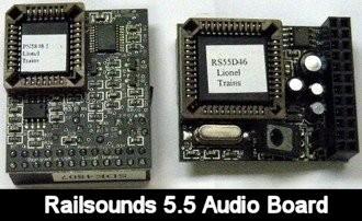
My Lionel SD-70ACe Western Pacific UP Heritage has no sound.  I have troubleshot some by swapping power supply and sounds boards between this and another one of my other SD-70ACes.  The power supply board tested fine in the working loco.  I found that there was an open in the wires to the speaker.  Would that cause a subcomponent to fail on the Railsounds 5.5 board?  The removable chips work when I swap them to a known working board.   


Last edited by Steims
Original Post

Replies sorted oldest to newest

@Steims posted:
I found that there was an open in the wires to the speaker.
Would that cause a subcomponent to fail on the Railsounds 5.5 board? Yes, absolutely an intermittent connection or worse, that potentially opens the door up for a short to frame ground or something else could and might blow the audio amplifier IC.
The removable chips work when I swap them to a known working board.   Good, you got lucky. That's about as lucky as you can expect. A typical fault it kills the chips and then you are soundless.
Unless you are good at SMD soldering, I would replace the board and ensure that the failure of open speaker wires or failing speaker is resolved to not kill the new board.
Second part is, you may not visibly be able to see the fault, and even though with a magnifier or microscope sometimes it can be seen, modern tiny electrics can fail and "look fine".
@Steims posted:

The pinched speaker wire only had an open and no short to ground.  That would cause the sound board to fail?    Seems like Lionel built their  electronics more robust than that to handle various failures and faults.  

I must ask the simple questions first. Did it how sound at one point? Everything else work fine in command as well as Conventional operations?

little advice, there are times a chip is defective from production and will show no outward signs. What ever board you are swapping too remember that of internal the “problem” could blow the test board.

the speaker wire was probably shorted and took the board with it, when you moved things to test you opened the short.

Last edited by ThatGuy
@ThatGuy posted:

little advice, there are times a chip is defective from production and will show no outward signs. What ever board you are swapping too remember that of internal the “problem” could blow the test board.

This is my TMCC test fixture, it's grown over the years.  I can test most aspects of TMCC and early Legacy modular boards on this one.

JWA TMCC Test Fixture

Attachments

Images (1)
  • JWA TMCC Test Fixture

This is my TMCC test fixture, it's grown over the years.  I can test most aspects of TMCC and early Legacy modular boards on this one.

JWA TMCC Test Fixture

I made my test bead from an old radio shack radio kit. I used the clip on part of the board and then went with e every thing else needed to test the boards. The one difference I see with your DC motor mount and mine is I can simulate a load with a drive wheel and slip clutch. I have seen boards that need to heat up to stop working.

I appreciate the advice especially since these boards are no longer available from Lionel.  I bought loco used and had no sound when it arrived.  I could tell some troubleshooting had already taken place.  

My takeaway from this is to make sure the speaker wire circuit has no open, has no short, and is not grounded to frame, before I power up a replacement sound board.  

@ThatGuy posted:

The one difference I see with your DC motor mount and mine is I can simulate a load with a drive wheel and slip clutch. I have seen boards that need to heat up to stop working.

I have a left hand that holds the flywheel if I need a quick load.  If I need a more sustained load, a power resistor across the motor does the job just fine.   This has been added to over the years as more situations for testing come up.  It started as a simple board tester.  If I knew it was going to grow like this, I'd have planned the layout better.

I have a left hand that holds the flywheel if I need a quick load.  If I need a more sustained load, a power resistor across the motor does the job just fine.   This has been added to over the years as more situations for testing come up.  It started as a simple board tester.  If I knew it was going to grow like this, I'd have planned the layout better.

If I knew what I know now……….we’ll you know…..LMAO

Sounds (ha sorry) like you killed the LM4861 audio driver. Lionel uses these in a bunch of their audio boards from my research. I think it drives the speaker directly, at least the tech sheet supports that. Perhaps the audio board might be salvageable if you replaced the driver.

I’ll give it try Norm as long as somebody can point to which discrete component that is on the board.  

Attachments

Images (1)
  • mceclip0

Maybe one superseded the other? I wasn't aware there were two amps on the audio board. I wonder if there's a block diagram of those boards somewhere in the world. The pinouts are fairly easy to find with a Google search but I've never seen the block diagram. It's still a real shame Lionel took those TMCC boards off the support site.

Edit: the other 8 pin SOIC might be an LM358 op amp.

Last edited by Norm Charbonneau
@ThatGuy posted:

I made my test bead from an old radio shack radio kit. I used the clip on part of the board and then went with e every thing else needed to test the boards. The one difference I see with your DC motor mount and mine is I can simulate a load with a drive wheel and slip clutch. I have seen boards that need to heat up to stop working.

Not to hijack Steim’s thread, ….but let’s see your test fixture!!….

Pat

@Steims posted:

There is an audio amplifier on both sides of the board.   One has an ever so slight blister on it so I think we are onto something here.   Digi-key has 2 models of this as LM4861M and LM4861MX, which one?

The two chips are the same, it's a packaging designation.

@Steims posted:

There is an audio amplifier on both sides of the board.

Sometimes those are used for power handling chores, could it be one it a non-audio use?

Attachments

Images (1)
  • mceclip0
Last edited by gunrunnerjohn

I've seen those 'Boomer' amps on the RS4 and RS5 boards, also on some of the ERR and Legacy sound boards. Without a block diagram, I couldn't say what the 358 op amp is for. I like to gawk at the boards once in a while and look up the components to get a rough idea on what does what. I still can't get over how overbuilt the old RS4/5 power supplies were. I can only guess that their audio engineers wanted zero sag when driving the sound. Whatever they did back they did well because those are still my favorite sounds.

I got one of those ESR meters for testing caps. I'm becoming a fan of all the cheap ebay/Amazon test equipment. You have to outsmart them a bit, but they are kind of fun to play with.

@Steims posted:

I tested all 4 caps on this Railsounds 5.5 board as well as another.  Seven of the 8 caps uF readings were in the ballpark of their listed rating.   The one with open stood out from all the rest.   The comparable cap on the other board read 232 uF.  I am using a digital Fluke with a cap testing function.  

Testing caps in circuit is a bit of a crap shoot, depending on what is connected, you can get all sorts of odd readings.  If the same cap on another board tested OK, then it makes sense.  It's pretty rare for a cap to be completely open without any physical appearance issues.

Well, when I remove those, I clip each lead, remove the body, then sweep the leads away with the iron, much less issue of PCB damage that way.  If you have a hot air tool, you might be able to lift the old one, but why bother?

The LM486 being a SO package isn't that difficult to solder, you just need a fine tip.  You will want to clean up the pads before installing the new chip.

Add Reply

Post

OGR Publishing, Inc., 1310 Eastside Centre Ct, Suite 6, Mountain Home, AR 72653
800-980-OGRR (6477)
www.ogaugerr.com

×
×
×
×
Link copied to your clipboard.
×
×