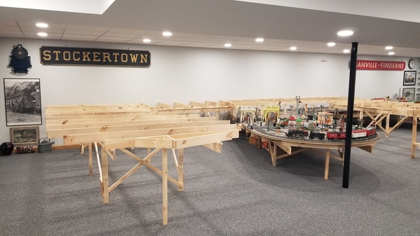
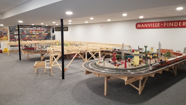
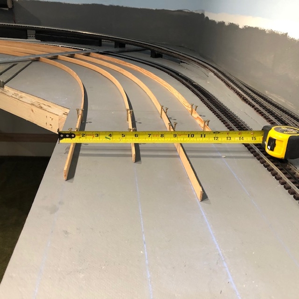
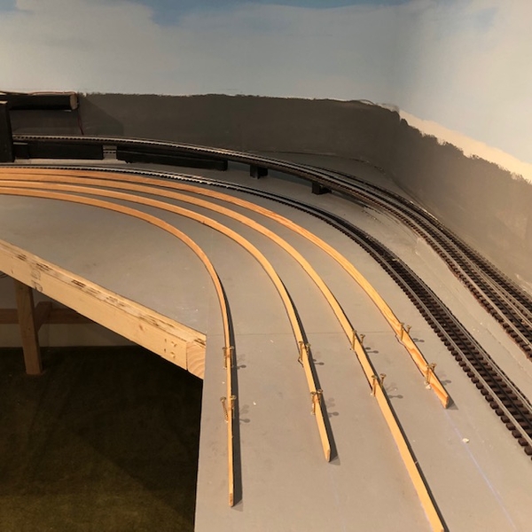
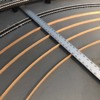
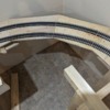
So, with the L-girder bench work built, the next step in my O gauge layout build is to install the plywood roadbed for the track work. This is something I have never done before and I am struggling on how to get started.

First, is laying out where the track will go. If I was using sectional track, I would assemble the track and lay it out over the joists and mark the outline right on the joists. I could then somehow transfer that to the plywood to create the roadbed sections. However, I will be using flex track, so I can't test fit the track ahead of time. So, how do I determine the layout for the roadbed? I have a cad drawing of the track design, so I suppose I could dimension up the plywood roadbed layout on the drawing and then transfer it on the plywood. Just seems like there must be an easier way.

It also appears to me that with the curved sections a lot of joints in the roadbed will be required to make up the full curved portions. Any tricks here on joint minimizing or the best way to handle this? Any easy way to make the curved sections?

I was leaning towards using 3/4" plywood for the roadbed. There are a few local cabinet makers that sell 3/4" cabinet grade plywood cut-offs in like 8" to 10" widths by 40" long. Maybe these would be useful, but probably not for the curves.

Any help is appreciated. Pictures would be great, as I'm a visual type person.

20230212_13460120230212_13461020230212_134639

Attachments

Images (3)
  • 20230212_134601
  • 20230212_134610
  • 20230212_134639
Last edited by NJCJOE
Original Post

Replies sorted oldest to newest

Joe,

I don't know if this might give you some idea's but might help. I am using Flex track over homasote, using very thin rips from the table saw. This allowed me to trace track centerlines; as well the bends naturally had a nice easement to them. You need to anchor the straight portion in 2 locations. It is also possible to adjust bends by making longer or shorter by pulling/ pushing on rips

thumbnail_IMG_2898thumbnail_IMG_2900thumbnail_IMG_2904

Attachments

Images (3)
  • thumbnail_IMG_2898
  • thumbnail_IMG_2900
  • thumbnail_IMG_2904

Joe, I’m guessing you don’t want the table top look of just plywood sheets. Nor at the price of plywood do you want to cut out curved sections and then figure out what to do with what’s not used. If you enjoy woodworking. I’ve seen a few layouts incorporate what’s called spline roadbed. Basically it’s 1/4 “x 1” strips cut from wood stock with a table saw. Sort of like lattice. They flex to sort of a perfect circle with built in easements. Used a lot by those that handlay track. You build the width up by putting little spacer blocks between each strip. You stagger the joints. O gauge probably requires 5 strips. You then either purchase or cut your own homesote roadbed and glue it to your wood risers. The homesote has slots cut into and will bend to follow the spline. It does save you some money and your layout will have a non sectional track like look to it. The curves usually end up where you want them to be but the have a nice flow like they weren’t drawn with a compass.

Pretty sure this is covered in Linn Westcotts book and there are numerous videos on line how to do it. Works well if you want your layout to have hills and valleys.

@NJCJOE posted:

So, with the L-girder bench work built, the next step in my O gauge layout build is to install the plywood roadbed for the track work. This is something I have never done before and I am struggling on how to get started.

First, is laying out where the track will go. If I was using sectional track, I would assemble the track and lay it out over the joists and mark the outline right on the joists. I could then somehow transfer that to the plywood to create the roadbed sections. However, I will be using flex track, so I can't test fit the track ahead of time. So, how do I determine the layout for the roadbed? I have a cad drawing of the track design, so I suppose I could dimension up the plywood roadbed layout on the drawing and then transfer it on the plywood. Just seems like there must be an easier way.

It also appears to me that with the curved sections a lot of joints in the roadbed will be required to make up the full curved portions. Any tricks here on joint minimizing or the best way to handle this? Any easy way to make the curved sections?

I was leaning towards using 3/4" plywood for the roadbed. There are a few local cabinet makers that sell 3/4" cabinet grade plywood cut-offs in like 8" to 10" widths by 40" long. Maybe these would be useful, but probably not for the curves.

Any help is appreciated. Pictures would be great, as I'm a visual type person.

20230212_13460120230212_13461020230212_134639

Joe, that looks to be a great addition to the layout! Layout size is no problem with a finished area you have.

Gene

@NJCJOE posted:

...I was leaning towards using 3/4" plywood for the roadbed. There are a few local cabinet makers that sell 3/4" cabinet grade plywood cut-offs in like 8" to 10" widths by 40" long. Maybe these would be useful, but probably not for the curves....

1/2" ply is plenty, and it's easier to bend than 3/4" on the grades.  Depending on the distances you're spanning, 3/8" might suffice.

Two approaches... Lay down a full sheet, trace an outline of your track, and cut with a saber saw (known as the cookie-cutter method) - uses more wood, but leaves flat areas to support buildings and accessories.  Or cut "sectional" pieces from the plywood and splice them together - less waste, but more splices.

My current layout doesn't have any grades, but I've used cookie cutter with 3/8" ply on a couple of small layouts.  Sorry, no construction pics.

@Steamfan77 posted:

Joe, maybe this link will help. Alex Muller’s Hidden Pass Junction RR might be helpful. Here is the link: https://ogrforum.ogaugerr.com/...-andamp-video?page=1. He also has a double track trestle, as well as some very interesting benchwork.

Andy

Link doesn't work.  I think there's a problem with the way the URL is being abbreviated in your post.

I searched for Hidden Pass Junction and found several threads - not sure which one you are referencing.

Regardless of which subroadbed approach you choose (plywood or spline) I would think a full size print of your track design would be desirable. You may find the plan doesn't quite work when scaled up, especially where switches are involved, but best to find out before you build. If you are not able to print one out, some kind of preliminary track laying, say on Homasote sheets, will vet the design before you start construction. Plans are notorious for needing to be changed.

Even where I designed the track work while fitting it, I was overoptimistic, and will shortly be rebuilding two derailment-prone problem areas

Hi Joe, what you're asking about is often referred to as subroadbed.  HO-scalers can get away with using Homasote or lauan plywood.  But with typical spacing of risers, there's no way those materials would support the weight of an O gauge Big Boy!  I agree that there just aren't enough illustrated step-by-step guides for O scale.

I bought all of the popular Kalmbach books about benchwork, and watched videos by Joe Fugate, Model Railroad Academy, etc.  Personally I think spline roadbed is labor-intensive, and overkill for what you're trying to do.  It might even be more difficult than 3/4" plywood to bend in the vertical plane for making grades, etc.

Plotting your track plan from SCARM, RR-Track, etc., in 1:1 is probably a worthwhile investment.  A commercial printer like Kinkos, Ridgeway, or even Office Max should be able to do that for a fee.  Next, I would cut out long sections of track from the paper plot, and glue them to a 4x8 sheet of high-quality 1/2" plywood, arranged so as to minimize waste.  Then, fire up the jigsaw!  Cut the sub-roadbed wider than the ties.  For sections of double mainline, yard, etc., you might use a single, wide piece of subroadbed to support the whole thing.  Be patient with yourself and start with plenty of cash, because mistakes will be made and material will be wasted!  If you want to make an omelet, you have to break eggs!

Yes, there will be splices!  If they are carefully assembled and well-supported, there should be no impact to operation of the trains.  I would have bubble levels of different lengths on hand-- everything from 4" long (i.e., the wheelbase of a steam loco) to perhaps 30" long.  The idea is that you don't want any bumps, humps, or sudden changes in slope.  Having a partner to adjust the height of the risers with clamps will help get everything nice and smooth before you screw things together permanently.  Also, an ability to make beveled cuts could be helpful, because I think sometimes the "tops" of the risers would have to be cut at a slight angle if they are supporting the sub-roadbed on a grade.

I'm right there with you in trying to learn this stuff, and had all the same questions you do, so I'll be following this thread!  For those of you with firsthand experience, please don't hesitate to correct any misinformation!

Last edited by Ted S

Joe, as Bob said, use trapezoids to make up the curves. The zoids are 1/2 inch birch ply ripped to 12 inch width and then cut on a 15 degree angle. Length at the midpoint or center is 18 inches.  Upper curve is 088 lower curve is 072.  Center rail to rail separation is 6 inches.  I needed 2 1/2 inches from the outer rail to the wall for the overhang on my BigBoy.  Zoids are joined using 1/2 splines - you can see the screw placement at the joints. 

I guessed at the 18 inch length. If I redo these, I would probably cut 14 inch wide boards, but keep the top length at 21 1/2 to give the extra 2 inches at the bottom.  If we calculate the perimeter length of these 2 curves, we should have center rail arc lengths of 69 and 56.5 inches. Center length of the zoids roughly total 72 inches.

I have to lay out the zoids for a single track curve with a width no more than 7 inches. Thinking about how to do that is giving me a headache. While the total arc length stays constant, each zoid will have to be significantly shorter with a corresponding shallower angle. The issue is to minimize the variation between the corner joint and the center of the zoid. I think I'll need 8 sections, maybe more, so that the track will nominally have the same amount of wood on either side.

Grade curve 1

Attachments

Images (1)
  • Grade curve 1
Last edited by ScoutingDad

Here is the math I forgot long long ago. Anyone remember the Law of Cosines?  Thought not

Here is the basic problem; even with the equation, we still have to guess at an angle. We then have to set the distance we want above and below the track. For the 072 diameter track, the equation will give the center line of the trapezoid (shown in yellow). We then have to add or subtract from 36 the additional roadbed needed for the track, plug those into the equation to get the length of the long and short sides of the trapezoid. After all, we need some kind of mark on the plywood to make the cut. The good thing about this is it will work for any needed curve diameter/radius. Sorry all, we need to use radii for the equation to work properly.

mceclip0

So in Bob's example with big "C" being 20 degrees, little "c" is only 12.5 inches. However if we increase the angle to 30 degrees, "c" becomes 18.6 inches.  Now its a matter of preference. More or fewer sections? More or less track variation spacing relative to the long and short sides of the trapezoid.  And you can look up the formula to calculate the angle if you want "c" to be 10 or 12 inches. Of course it may make more sense to use the number of sectional track needed to make a 90 in this case 4 or angles of 90/4 = 22.5 degrees >> also 14 inches centerline length. Remarkably Ross 072 sectional is 14 inches.

By the way - if you try to do the calculation in Excel - its "cos" function requires RADIANS. So within Excel the correct formula is  COS(RADIANS(angle))  Guess how I figured that out. I knew the calculated length could not be longer then the sides - what the heck?  Something is wrong.

Attachments

Images (1)
  • mceclip0
Last edited by ScoutingDad

Also did the 'zoid thing.  1/2" plywood, sanded one side. 

Thought I'd pass along my serendipitous spline joinery...  When a friend of mine departed the hobby he gave me a lot of...'stuff'...that I had no idea at the time how I'd use it.  Included was a HUGE bundle of craft sticks...better known in my day as "Popsicle" sticks.  Nowadays you can buy them CHEAP at a craft store...box of 1,000 for around $10, I believe.

Anyhow, in addition to the table saw and radial saw I have/used to cut the 'zoids', I also have a Hegner model-makers circular saw.  And I discovered that its blade kerf is exactly the same thickness as one of those popsicle sticks.

So, as I finished each 'zoid section I cut a dado into each end about 1/2 the width of a popsicle stick.  I was careful to run the 'top' (sanded...as it would lie on the layout) side of each 'zoid against the fence.  That way there would be minimal, if any, misalignment with the adjoining 'zoid.  I spot-glued the popsicle stick into only one side of each joint.  (Someday someone+ will have to take the basement monster down.  May as well make it easier while I think of it!).

Anyhow...a couple of photos...

IMG_9335IMG_9338

BTW...if the stretch between support posts was judged to be too far apart for the possible max. weight of passing trains, and if that span included one of these splined joints, I would often simply screw a strip of scrap wood to the bottom of the plywood for reinforcement.  It was only necessary in a few locations.  Otherwise the whole setup has served well for 20+ years.

FWIW...

KD

Attachments

Images (2)
  • IMG_9335
  • IMG_9338

@RSJB18 Ha - I have a story to tell about that Python bit - probably not appropriate here but clean ... college fraternity days of course ...

@Ted S  Ted - methods and utility are the same. To me the issue is one: we are not using large expanses of plywood, but narrow strips of ply to support the track and two: cutting large diameter curves from sheets of ply can be very wasteful and expensive.  Smaller diameter curves can be laid out and cut from larger sheets of plywood fairly efficiently. (thinking 90 degrees of arc, 45s would have less waste). All of this depends on how much work you want to put into it. Depending on the layout, the cookie cutter method can work quite well. I am using all 3 on my layout rebuild. I am using the L-girder approach simply because I modified my first railroad at least 4 times in 3 years making it "better". Even this "new" version will change over time. I am already thinking about other options as I am building this one. To me L-Girder offers the most flexibility to make changes to a railroad. 

Add Reply

Post
The Track Planning and Layout Design Forum is sponsored by

AN OGR FORUM CHARTER SPONSOR

OGR Publishing, Inc., 1310 Eastside Centre Ct, Suite 6, Mountain Home, AR 72653
800-980-OGRR (6477)
www.ogaugerr.com

×
×
×
×
Link copied to your clipboard.
×
×