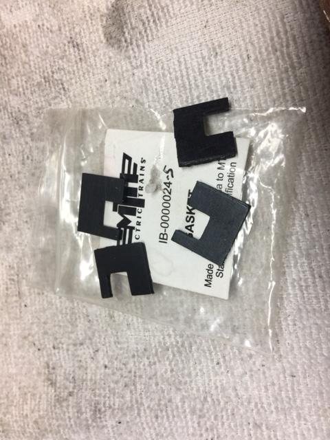
Valhalla - my parts for the smoke unit showed up yesterday; excellent response from Lionel's parts lady Katie.  Now, I have a series of questions which I will post.

First, regarding the fan motors (see the motors in the reservoir below): each fan motor fits into the reservoir and are attached to it by 2 micro screws (DOH, I didn't order the screws); each motor has 2 terminals; one terminal is marked with a white dot.  On the old motors, that white dot terminal is used for the black ground wire, the other unmarked terminal is for the red power wire.  Just looking for verification from the forum. IMG_0241

Attachments

Images (1)
  • IMG_0241

Yes, those fans are a press fit, don't glue them on! Be sure to not press them down too far and seat them on the bottom, you should have them low enough to not hit the circuit board and high enough to not scrape on the bottom. So spinning freely would be correct. As to the drop of oil, you can put the smallest drop you can do onto the shaft before you put the fan blades on if it makes you feel better, I don't usually oil my new fan motors but I don't see how that could hurt. Perhaps other member with more experience in that area could be of assistance.

Thanks Dave and Romiller49!!  I will just press them on as you advised; I think I will forego the glue and the oil.  I am guessing that they can be removed from the motor shaft if necessary by gently prying them up thru the air channel in the reservoir.

Now, on to another question:  I will have to solder red and black leads to the fan motors; I am thinking 20g or 22g wire.  The board has very short red and black leads coming out of it for the fan motors  (they couldn't have made them shorter) and those leads are soldered on the top side and bottom side of the board.  Is splicing/soldering the leads from the fan motors to the short leads on the board the right way??

IMG_0240

Attachments

Images (1)
  • IMG_0240
Last edited by RickM46
RickM46 posted:

Thanks Dave and Romiller49!!  I will just press them on as you advised; I think I will forego the glue and the oil.  I am guessing that they can be removed from the motor shaft if necessary by gently prying them up thru the air channel in the reservoir.

Now, on to another question:  I will have to solder red and black leads to the fan motors; I am thinking 20g or 22g wire.  The board has very short red and black leads coming out of it for the fan motors  (they couldn't have made them shorter) and those leads are soldered on the top side and bottom side of the board.  Is splicing/soldering the leads from the fan motors to the short leads on the board the right way??

IMG_0240

Don't pry them up from the side, that is how you bend the shaft and ruin the motor. Using small needle nose pliers grip the center and pull them up that way.

Some of the boards that I get don't even have those wire leads on them, consider yourself lucky yours came with them. Yes you solder to those wires using an appropriate gauge wire.

Yep, you just touch the iron to the joint and pull the wire out.  Then, to clean the hole, just heat it again and tap the board straight down on the bench quickly, the solder will pop out.  Obviously, we're doing this with the proper sized soldering iron.

You can use much finer wire, the motors only draw around 30-40ma, so any size wire up to around #30 is fine.

Last edited by gunrunnerjohn
Davety posted:
RickM46 posted:

Thanks Dave and Romiller49!!  I will just press them on as you advised; I think I will forego the glue and the oil.  I am guessing that they can be removed from the motor shaft if necessary by gently prying them up thru the air channel in the reservoir.

Now, on to another question:  I will have to solder red and black leads to the fan motors; I am thinking 20g or 22g wire.  The board has very short red and black leads coming out of it for the fan motors  (they couldn't have made them shorter) and those leads are soldered on the top side and bottom side of the board.  Is splicing/soldering the leads from the fan motors to the short leads on the board the right way??

IMG_0240

Don't pry them up from the side, that is how you bend the shaft and ruin the motor. Using small needle nose pliers grip the center and pull them up that way.

Some of the boards that I get don't even have those wire leads on them, consider yourself lucky yours came with them. Yes you solder to those wires using an appropriate gauge wire.

Thanks Dave for the tip on the needle nose pliers and the fan blades.

Now, I have one last hurdle: There is a mounting screw in the center of the board that goes into the reservoir.  You can see its threaded end below.  However, the funnel is press fitted into the board over the mounting screw so you cannot get at it.  Tried to pull the funnel off with my finger tips but it is pressed tight into the board.  You can see the two black funnel ends just emerging out of the board under the heating elements.  There are 4 other mounting holes at the corners.  I guess I could just drill out the receiving hole in the reservoir and not use the center mounting screw.  Any suggestions???

IMG_0247

Attachments

Images (1)
  • IMG_0247

It’s pretty clear from the photos that the funnel is a really tight press fit into the holes in the PCB board as the edges of the holes are bent in the direction the funnel inlets would have been inserted. I’d use the flat side of a screwdriver blade to gently nudge the funnel inlets out of those holes.

Regarding the white dots on the fan motors: I think that these actually indicate the + terminal but these motors originally may have been wired to spin CCW so the - lead would be wired to the white dot terminal. Check the original motor wiring to be sure but a couple of posts on the first page of this thread explain the reason for the reverse wiring.

Yes, Hancock52, the funnel nozzles are a really tight fit into the holes - when I first took the board out of its bag, there were very small strings of fragments of board resting against the funnel nozzles protruding over the heating elements - they must have used some sort of press to insert the nozzles into the board causing the fragments - that has got to be a headache for those repairing the units.

Regarding the fan motors, the old units have the negative black leads soldered to the white dot terminals and I am thinking that would make the fans spin CW with the convex part of the blades facing the direction of spin - I will verify that before soldering. 

Update: upon later investigation, the NEW motors produce CCW rotation with the black lead attached to the white dot terminal with the concave part of the fan doing the pushing thru the air channel to the wick chamber.  Am not sure what direction the fan spins on the old motors with the black lead currently attached to the white dot.

Last edited by RickM46

The convex part of the blades should face in the direction of the spin.  That's an air noise reduction measure for the fans.

When I remove the solder, I hold the board above the bench a couple inches, heat it with the iron, and then quickly tap it on the bench.  You don't try to keep the iron in contact with it, if you immediately tap it after removing the iron, it works fine.

GRJ: Thanks for the tips on de-soldering - will do. 

And just tested the NEW fan motors with significant results:  Attaching a red + battery lead to the white dot terminal and the black lead to the other terminal produces CW rotation with the convex part of the blades facing the direction of rotation.  This is the opposite to the way the old motors are connected - black lead to the white dot terminal.  On the new motors, I will attach the red lead to the white dot to get CW rotation.

I hate to contradict myself, but maybe CW is wrong for this smoke unit.  Looking at the picture, it's obvious from the positioning of the fan exhaust that the motors probably should run CCW.  I think CW would result in much less airflow with that air chamber design.  Obviously, the folks that designed the impellers and the folks that designed the smoke unit don't talk.

IMG_0223

GRJ, I think you hit the nail on the head as others in this thread have written - there is some disparity in design.  Right after I said 'On the new motors, I will attach the red lead to the white dot to get CW rotation' I had second thoughts.  As Mike R wired the motors for CCW by attaching the black lead to the white dot, I will do the same - at least air will be pushed through the exhaust channel of the reservoir to the wick chamber by CCW rotation with the concave part of the fan blade doing the pushing.  I think the design of the exhaust channel of the reservoir to the wick chamber trumps concave vs convex of the fan.

Last edited by RickM46
RickM46 posted:

GRJ, I think you hit the nail on the head as others in this thread have written - there is some disparity in design.  Right after I said 'On the new motors, I will attach the red lead to the white dot to get CW rotation' I had second thoughts.  As Mike R wired the motors for CCW by attaching the black lead to the white dot, I will do the same - at least air will be pushed through the exhaust channel of the reservoir to the wick chamber by CCW rotation with the concave part of the fan blade doing the pushing.  I think the design of the exhaust channel of the reservoir to the wick chamber trumps concave vs convex of the fan.

As I said in an earlier post in this thread, I have come across this apparent mismatch of the impeller blades' shape and exhaust channel configuration before on another VL engine with plastic smoke units, the Baldwin Centipede. Lionel has never mentioned anything about the difference between these and "normal" smoke units where it's CW rotation of the impeller blades that will push air directly through the channel. 

But incidentally, when I re-wired my Centipede fan motors to spin CW instead of CCW (as originally wired), it made no discernible difference to the smoke output; it was neither obviously better nor worse. 

Hard to believe that the designers of these units did not recognize that stock impellers have always had the convex side of the blade run CW to propel air (but I'll be corrected if someone has ever seen an impeller made to run the other way). I did think about turning the impellers in my Centipede's units upside down but decided it would be too difficult to get the spacing on the fan motor spindle right. Besides, the bottom of the impeller is a solid round piece and having it on top might have impeded the airflow to the blades. 

Last edited by Hancock52
gunrunnerjohn posted:

I hate to contradict myself, but maybe CW is wrong for this smoke unit.  Looking at the picture, it's obvious from the positioning of the fan exhaust that the motors probably should run CCW.  I think CW would result in much less airflow with that air chamber design.  Obviously, the folks that designed the impellers and the folks that designed the smoke unit don't talk.

IMG_0223

Here’s a picture of MTH impeller. Their fan spins CW with air being pushed via the convex part of the fan allowing total air escape into and across the resistor area. Unfortunately the Lionel design does not allow this to happen no matter what you do. If theirs spins CW the air smacks right back into the fan housing greatly limiting proper air flow. If theirs spins CCW as designed the air is trapped inside the fan housing via the concave shape of the fan greatly diminishing the air flow out to the resistor side of the smoke unit. Lionel needs to re- design their fan and this just may solve all the burnt batting issues. 

Attachments

Images (1)
  • 4BC2DFFA-FF27-434B-83DF-AA79BEB24A9E

To be blunt, if Mike Reagan wired this unit - and indeed it originally came wired - so that the impeller spins CCW, that would be good enough for me. What the thinking was behind this design only someone who was involved in it can tell us. It looks like a mistake or at least very odd to me. 

RickM46, your idea of widening the airflow outlet is very interesting to me but again, what the thinking was behind the original design would help in deciding whether to try this experiment. Also whether another replacement part is available in case the cutting goes wrong!

For purposes of comparison, I have looked out the thread I posted on the VL Centipede units, which also concerned a completely separate oddity about a Lionel spare part for those units, an internal metal heat shield that was not part of the stock unit. The thread is here: https://ogrforum.ogaugerr.com/...onel-smoke-unit-part

I never found out what that part was designed to do and how it was meant too fit in the plastic smoke units. If anything, the units were even odder than the one you are working on; as the photo below shows, the airflow from the impeller to the resistor has to go through at least a full 90 degree bend, which I can't think is very efficient:

2_StockUnit_VL_Centipede

These units also came from the factory with the fan motor wired to spin CCW (negative wire to terminal marked with white dot) so that the concave side of the impeller blades was pushing the air towards the resistor:

3_Wiring_VL_Centipede

It would be interesting if someone from Lionel (or Mike R.) explained the theory behind this arrangement but short of asking them or him I don't see the logic of it. 

Anyway, as I have said in my last post, wiring the fan motor to spin CW in these units had no effect on the smoke output, good or bad, and so maybe the motor and impeller generate enough airflow for the unit to operate as designed whichever way you wire them. 

Attachments

Images (2)
  • 2_StockUnit_VL_Centipede
  • 3_Wiring_VL_Centipede
RickM46 posted:

I guess if one wanted to be adventurous with a Dremel, you could cut that upper corner portion of the exhaust channel to be like the lower portion; I looked at my new reservoir and it looks like that shoulder is solid material; but not an effort for my unsteady hands.

IMG_0223

I wouldn’t do that. You’ll definitely ruin the unit. Put it back together as is and just keep it loaded with fluid. 

I am grateful for the patience of the forum; however, I have yet another situation with the New PCB board as delivered and as compared to the old board.  On the old board, the tops of the thermistors are even with the tops of the heating resistors.   On the new board, the tops of the thermistors are even with the bottoms of the heating resistors.  See pics below.  That can't be right or is it??  The top pic is the old board.  BTW, I woke up at 4AM and this disparity was the first thought that hit my mind --- I need to get a life.

IMG_0271IMG_0281

Attachments

Images (2)
  • IMG_0271
  • IMG_0281
Last edited by RickM46

Interesting to me (and maybe need to get a life too) is that it's the resistor in the new unit that looks to be out of place i.e. too high whereas the thermistors are at the same level as the original. It's also at a slight angle. So pulling up the thermistors to be at the resistor height means that they and the resistor will be seated slightly deeper in the smoke wadding than in the original, which may make no difference but you won't know without testing the unit. 

More generally, the whole assembly looks kind of bodged together with the wire leads to these components being as long as they are. But that's just my amateur opinion. 

Hancock52 posted:

Interesting to me (and maybe need to get a life too) is that it's the resistor in the new unit that looks to be out of place i.e. too high whereas the thermistors are at the same level as the original. It's also at a slight angle. So pulling up the thermistors to be at the resistor height means that they and the resistor will be seated slightly deeper in the smoke wadding than in the original, which may make no difference but you won't know without testing the unit. 

More generally, the whole assembly looks kind of bodged together with the wire leads to these components being as long as they are. But that's just my amateur opinion. 

They are that long so the components are in the wick and there is still room between the board and component for air flow.

Gene Anstine

Thanks GRJ, Hancock52, and Gene; yes, that new assembly has 2 flaws - press fitting the funnel into the board so it cannot be removed and thus orphaning the mounting screw under it and the positioning of the thermal elements - so much for precision; but, it is what it is.

I was thinking I could take a measurement of the distances of the elements from the old board and make the elements of the new board the same; either gently pressing down or pulling up.  Per Jon Z., it is critical that there be wet wick between the thermistor and resistor.

Last edited by RickM46
grfd59 posted:

They are that long so the components are in the wick and there is still room between the board and component for air flow.

Gene Anstine

I see your point but would just add the following.

The VLBB smoke unit issue I have is with the blowdown unit, not the dual stack unit Rick is working on but the same basic issue seems to arise. I have not opened up my engine yet but I know the blowdown unit is equipped with a thermistor that might be misaligned. Lionel stocks some different variations of the PCB for this unit. The first one below has the thermistor mounted on wiring that is similar to old TAS smoke units and those used by 3rd Rail; the wiring is rigid and bent in a U shape that fixes the position of the thermistor relative to the resistor. The second one has the extra wire. Possibly just a difference in the way that these were assembled at the factory but the first option seems better constructed to me (thermistor less likely to be moved out of correct alignment when the unit is screwed on to the reservoir and presses into the smoke batting) :

392894ogsu

391361003

I should also note that this particular unit as a whole is very similar to the problematic ones in my VL Centipede but I don't recall those being equipped with a thermistor. 

Attachments

Images (2)
  • 392894ogsu
  • 391361003

Add Reply

Post

OGR Publishing, Inc., 1310 Eastside Centre Ct, Suite 6, Mountain Home, AR 72653
800-980-OGRR (6477)
www.ogaugerr.com

×
×
×
×
Link copied to your clipboard.
×
×